Note: Descriptions are shown in the official language in which they were submitted.
CA 02544478 2006-05-02
WO 2005/065580 PCT/US2004/038964
-1-
STENT TO BE DEPLOYED ON A BEND
Backgr,-ouzld of the Invention
Stems are placed or implanted within a variety of bodily vessels
including in coronary arteries, renal arteries, peripheral arteries including
illiac arteries,
arteries of the neck and cerebral arteries, veins, biliary ducts, urethras,
fallopian tubes,
bronchial tubes, the trachea, the esophagus and the prostate.
Stems are available in a wide range of designs. One popular stmt design
includes a plurality of serpentine rings having alternating turns. The rings
are made of
interconnected struts. Adj acent rings are interconnected via connecting
elements.
Generally, when stems are deployed in areas of high curvature they are
bent so that the struts on the outside of the curve are farther apart than
those on the
inside of the curve. This arrangement typically provides poor scaffolding on
the outside
of the bend and/or possibly result in overlapping struts on the inside of the
bend.
There remains a need for stems which provide adequate scaffolding in
areas of high curvature.
Without limiting the scope of the invention a brief summary of some of
the claimed embodiments of the invention is set forth below. Additional
details of the
summarized embodiments of the invention and/or additional embodiments of the
invention may be found in the Detailed Description of the Invention below.
A brief abstract of the technical disclosure in the specif canon is
provided as well for the purposes of complying with 37 C.F.R. 1.72.
All US patents and applications and all other published documents
mentioned anywhere in this application are incorporated herein by reference in
their
entirety.
Summary of the Invention
In one embodiment, a stmt may comprise a first segment having a
plurality of closed serpentine circumferential bands. Adjacent closed
serpentine
circumferential bands may be connected to one another. Each closed serpentine
circumferential band may have a plurality of struts, each strut having a
length, and the
struts which are circumferentially adj acent to one another may be connected
one to the
CA 02544478 2006-05-02
WO 2005/065580 PCT/US2004/038964
_2_
other by a turn. The struts may generally increase in length from a minimum
strut
length to a maximum strut length, and then may generally decrease in length
from the
maximum strut length to the minimum strut length as the circumferential band
is
traversed in its entirety in a clockwise direction. Desirably, the struts of
maximum
length in the closed serpentine bands may be generally longitudinally aligned
with one
another.
In another embodiment, an unexpended stmt may comprise a plurality of
interconnected struts disposed in a tubulax structure. The tubular structure
may include
a first portion and a second portion, each portion including struts which
generally
increase in length to a maximum length and then generally decrease in length
to a
minimum length as the stmt is traversed circumferentially about a longitudinal
axis. A
maximum length strut of the first portion may be longitudinally aligned with a
maximum length strut of the second portion. The first portion may be proximal
to the
second portion.
In another embodiment, a stmt may comprise a plurality of
interconnected struts defining a wall surface. The wall surface may include a
segment
having a strip extending from one end of the segment to the other end of the
segment,
and extending over a portion of the circumference of the stmt. The strip may
have a
plurality of rows of interconnected struts which are of greater length than
the remaining
struts of the segment.
In another embodiment, a stmt may comprise a plurality of
interconnected struts defining a wall surface. The wall surface may include a
segment
having a strip extending from one end of the segment to the other end of the
segment
and extending over a portion of the circumference of the stmt. The strip may
have a
plurality of rows of interconnected struts which are of greater flexibility
than the
remaining struts of the segment.
Additional details and/or embodiments of the invention are discussed
below.
These and other embodiments which characterize the invention are
pointed out with particularity in the claims annexed hereto and forming a part
hereof.
However, for a better understanding of the invention, its advantages and
objectives
obtained by its use, reference should be made to the drawings which form a fiu-
ther part
CA 02544478 2006-05-02
WO 2005/065580 PCT/US2004/038964
-3-
hereof and the accompanying descriptive matter, in which there are illustrated
and
described various embodiments of the invention.
Brief Description of the Figures
Figure 1 shows a flat pattern design of an embodiment of an inventive
stmt.
Figure 2 shows another flat pattern design of an embodiment of an
inventive stent.
Figure 3 shows another flat pattern design of an embodiment of an
inventive stmt.
Figure 4 shows another flat pattern design of an embodiment of an
inventive stmt.
Figure 5 shows another flat pattern design of an embodiment of an
inventive stmt.
Figure 6 shows another flat pattern design of an embodiment of an
inventive stmt.
Figure 7 shows another flat pattern design of an embodiment of an
inventive stmt.
Figure 8 shows another flat pattern design of an embodiment of an
inventive stent.
Figure 9 shows another flat pattern design of an embodiment of an
inventive stmt.
Figure 10 shows another flat pattern design of an embodiment of an
inventive' stent.
Figure 11 shows another flat pattern design of an embodiment of an
inventive stmt.
Figure 12 shows another flat pattern design of an embodiment of an
inventive stmt.
Figure 13 shows an embodiment of an inventive stmt deployed in a
curved vessel.
CA 02544478 2006-05-02
WO 2005/065580 PCT/US2004/038964
-4-
Detailed Description of the Invention
This invention may be embodied in many different forms. This
description is an exemplification of the principles of the invention and is
not intended to
limit the invention to the particular embodiments illustrated.
' For the purposes of this disclosure, unless otherwise indicated, identical
reference numerals used in different figures refer to the same component.
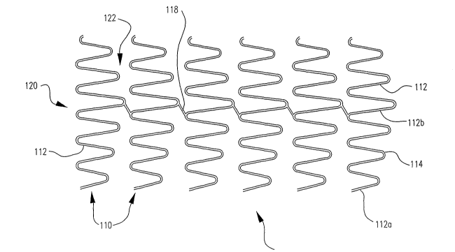
In one embodiment, the invention is directed to a stmt, such as that
shown at 100 in Fig. 1, comprising a plurality of interconnected closed
serpentine
circumferential bands 110. Adjacent closed serpentine circumferential bands
110 may
be connected to one another by at least one connecting element 118. Each
closed
serpentine circumferential band 110 comprises a plurality of struts 112.
Struts 112
which are circumferentially adj acent to one another are connected to one
another by a
turn 114. The length of the struts 112 within a band 110 generally increases
in length
from a minmum strut length to a maximum strut length and then generally
decreases in
length from the maximum length to the minimum length as the circumferential
band is
traversed in its entirety in a clockwise direction. A strut of maximum length
is shown at
112b while a strut of minmum length is shown at 112a. The term 'generally
increasing'
allows for the possibility that some adj acent struts 112 are of the same
length or within
manufacturing tolerances of one another. Similarly, the term 'generally
decreasing'
allows for the possibility that some adjacent struts 112 are of the same
length or within
manufacturing tolerances of one another. Desirably, the struts 112 continually
increase
in length over a portion of the circumferential band 110 and then continually
decrease in
length over the remaining portion of the circumferential band 110. The term
'continually increase' requires that each strut 112 in the direction of
increasing length be
longer than the previous strut 112. The, term 'continually decrease' requires
that each
strut 112 in the direction of decreasing length be shorter than the previous
strut 112.
Adjacent bands 110 are connected one to the other via one or more connectors
116.
Each band of the stent will have a distribution of struts ranging from a
smallest strut to a largest strut. The distribution of struts may be the same
in each band
or may differ in one or more of the bands. Thus, the maximum strut length of
the struts
of a first circumferential band may or may not be the same as the maximum
strut length
of the struts of a second circumferential band. Similarly, the minimum strut
length of
the struts of a first circumferential band may or may not be the same as the
minimum
CA 02544478 2006-05-02
WO 2005/065580 PCT/US2004/038964
-5-
strut length of the struts of the second circumferential band. In some
embodiments, the
number of struts per band may differ between some of the bands. Also, the
range of
strut width within a band may differ among some of the bands.
Typically, as shown in Fig. l, the struts of maximum length 112b in the
closed serpentine circumferential bands 110 are generally longitudinally
aligned with
one another. For the purposes of this disclosure, two struts 112 are in
general
longitudinal alignment with each other if a line which is parallel to the
longitudinal axis
of the stmt can be drawn between the two struts 112. The line may be straight
in the
case of a stmt without curvature or may be curved in the case of a stmt with
curvature.
As shown in Fig. 1, each closed serpentine circumferential band 110 has
a first end 120 and a second end 122, and the turns 114 at only one of the
first and
second ends are in general circumferential alignment. The toms 114 at the
other end are
generally not in circumferential aliglnnent. For the purposes of the
disclosure, turns 114
are in circumferential aligmnent if they extend to the same longitudinal
extent along the
length of the stent 100. All of the bands 110 may be similarly oriented as
shown in Fig.
1 so that the unaligned end of one band 110 faces the aligned end of a
directly adjacent
band 110.
It is also within the scope of the invention, as shown in Fig. 2, for some
of the bands 110 to be oriented in one direction and for other bands 1 10a to
be oriented
in the opposite direction. For example, in the stmt 100 of Fig. 2, the bands
110 located
toward the proximal end 130 of the stmt 100 have unaligned second ends 122,
while the
bands 110a located toward the distal end 132 of the stmt have unaligned first
ends 120.
As shown, bands 110 and bands 110a are oppositely oriented. Thus, in the
middle of
the stmt 100, there may be a first serpentine band 110 adjacent to a second
serpentine
band 110a, wherein the non-aligned turns 114 of the first serpentine band 110
face the
non-aligned turns 114 of the second serpentine band 110a.
It is further within the scope of the invention for the closed serpentine
bands 110 to have non-aligned turns 114 at both the first end 120 and the
second end
122, as shown by way of example in Fig. 3.
In another embodiment as shown at 100 in Fig. 4, the invention is
directed to a stmt comprising a plurality of interconnected serpentine
circumferential
bands 110. Adjacent closed serpentine circumferential bands 110 may be
connected to
one another by at least one connecting element 11 ~.
CA 02544478 2006-05-02
WO 2005/065580 PCT/US2004/038964
-6-
Each serpentine circumferential band 110 may have a first end 120 and a
second end 122, and may comprise a plurality of struts 112. Struts 112 which
are
circumferentially adjacent to one another are connected to one another by a
turn 114.
The length of the struts 112 within a band 110 generally increases in length
from a
minimum strut length 112a to a maximum strut length 112b and then generally
decreases in length from the maximum length 112b to the minimum length 112a as
the
circumferential band 110 is traversed in its entirety in a clockwise
direction.
Each circumferential band 110 within a stmt 100 may have struts 112
that vary in length as compared to other circumferential bands 110 within the
stmt 100.
Thus, the maximum strut length 112b of a first circumferential band 110 may or
may
not be the same as the maximum strut length 112b of a second circumferential
band 110.
Similarly, the minimum strut length 112a of a first circumferential band 110
may or
may not be the same as the minimum strut length 112a of a second
circumferential band
110. In some embodiments, the maximtun strut length 112b of a first
circumferential
band 110 may be the same as or even shorter than the minimum strut length 112a
of a
second circumferential band 110.
As shown in Figure 4, all of the turns 114 at the proximal end 130 of a
stmt 100 may be in general circumferential alignment with one another. All of
the turns
114 at the distal end 132 of a stmt 100 may be in general circumferential
alignment with
one another. Interior turns 114, which are not located at either the proximal
end 130 or
the distal end 132 of the stmt 100, may be out of circumferential alignment
with other
interior turns 114 that are located on the same side 120, 122 of the same
serpentine
circumferential band 110.
As shown in Figure 4, an inventive stmt 100 may include a strip or
backbone section 140. Desirably, a strip 140 comprises a zone extending across
at least
a portion of the length of the stmt 100 and across at least a portion of the
circumference
of the stmt 100. Tn some embodiments, all struts 112 located within a strip
140 may
comprise maximum length struts 112b. In some embodiments, a strip 140 may
contain
all of the maximum length struts 112b included in a stmt 100.
In some embodiments, such as shown in Figure 4, a strip may include all
of the connecting elements 118 of the stmt 100.
When an inventive stmt 100 is deployed on a curve, desirably the stmt
100 will be positioned having a strip 140 located at the outside of the curve.
CA 02544478 2006-05-02
WO 2005/065580 PCT/US2004/038964
In another embodiment as shown at 100 in Fig. 5, the invention is
directed to a stmt comprising a plurality of interconnected serpentine
circumferential
bands 110. Adj scent closed serpentine circumferential bands 110 may be
connected to
one another by a plurality of connecting elements 118.
Each serpentine circumferential band 110 may have a first end 120 and a
second end 122, and may comprise a plurality of struts 112. Struts 112 which
are
circumferentially adjacent to one another are connected to one another by a
tum 114.
The length of the struts 112 within a band 110 generally increases in length
from a
minimum strut length 112a to a maximum strut length 112b and then generally
decreases in length from the maximum length 112b to the minimum length 112a as
the
circusnferential band 110 is traversed in its entirety in a clocl~wise
direction.
Each circumferential band 110 within a stent 100 may have struts 112
that vary in length as compared to other circumferential bands 110 within the
stmt 100.
Thus, the maximum strut length 112b of a first circumferential band 110 may or
may
not be the same as the maximum strut length 112b of a second circumferential
band 110.
Similarly, the minimum strut length 112a of a first circumferential band 110
may or
may not be the same as the minimum strut length 112a of a second
circumferential band
110. In some embodiments, the maximum strut length 112b of a first
circumferential
band 110 may be the same as or even shorter than the minimum strut length 112a
of a
second circumferential band 110.
All of the turns 114 at the proximal end 130 of a stent 100 may be in
general circumferential alignment with one another. All of the turns 114 at
the distal
end 132 of a stmt 100 may be in general circumferential alignment with one
another.
Interior turns 114, which are not located at either the proximal end 130 or
the distal end
132 of the stmt 100, may be out of circumferential alignment with other
interior turns
114 that are located on the same side 120, 122 of the same serpentine
circumferential
band 110.
Each connecting element 118 may be connected at one end to a turn 114
of a first serpentine circumferential band 110 and may be connected at the
other end to a
turn 114 of an adjacent serpentine circumferential band 110. As shown in
Figure 5, the
length of circumferentially adjacent connecting elements 118 may vary. In some
embodiments, the length of the connector struts 118 between two adjacent
serpentine
circumferential bands 110 may generally increase in length from a minimum
connecting
CA 02544478 2006-05-02
WO 2005/065580 PCT/US2004/038964
_g_
element length 118a to a maximum connecting element length 118b, and then
generally
decrease in length from the maximum connecting element length 118b to the
minimum
connecting element length 118a about the circumference of the stmt 100. In
some
embodiments, the length of the connecting elements 118 may be inversely
proportional
to the length of struts 112 located adj acent to the connecting elements 118.
In another embodiment as shown at 100 in Fig. 6, the invention is
directed to a stmt comprising a plurality of interconnected serpentine
circumferential
bands 110. Adjacent closed serpentine circumferential bands 110 may be
connected to
one another by a plurality of connecting elements 118.
Each serpentine circumferential band 110 may have a first end 120 and a
second end 122, and may comprise a plurality of struts 112. Struts 112 which
are
circumferentially adjacent to one another are connected to one another by a
turn 114.
The length of the struts 112 within a band 110 generally increases in length
from a
minimum strut length 112a to a maximum strut length 112b and then generally
decreases in length from the maximum length 112b to the minimum length 112a as
the
circumferential band 110 is traversed in its entirety in a clockwise
direction.
Each circumferential band 110 within a stmt 100 may have struts 112
that vary in length as compared to other circumferential bands 110 within the
stmt 100.
Thus, the maximum strut length 112b of a first circumferential band 110 may or
may
not be the same as the maximum strut length 112b of a second circumferential
band 110.
Similarly, the minimum strut length 112a of a first circumferential band 110
may or
may not be the same as the minimum strut length 112a of a second
circumferential band
110. In some embodiments, the maximum strut length 112b of a first
circumferential
band 110 may be the same as or even shorter than the minimum strut length 112a
of a
second circumferential band 110.
All of the turns 114 at the proximal end 130 of a stmt 100 may be in
general circumferential alignment with one another. All of the turns 114 at
the distal
end 132 of a stmt 100 may be in general circumferential alignment with one
another.
Interior turns 114, which are not located at either the proximal end 130 or
the distal end
132 of the stmt 100, may be out of circumferential alignment with other
interior turns
114 that are located on the same side 120, 122 of the same serpentine
circumferential
band 110.
CA 02544478 2006-05-02
WO 2005/065580 PCT/US2004/038964
-9-
Each connecting element 118 may be connected at one end to a turn 114
of a first serpentine circumferential band 110 and may be connected at the
other end to a
turn 114 of an adjacent serpentine circumferential band 110. Each connecting
element
118 may include curvature, and thus may include a peak 124. The length of a
connecting element 118 may vary from the length of a circumferentially adj
acent
connecting element 118. Longer connecting elements 118 may further include a
trough
126. Generally, a peak 124 may be connected via an inflection point to a
trough 126.
Still longer connecting elements 118 may include a plurality of peaks 124, and
may also
include at least one trough 126 or a plurality of troughs 126.
Curvature in a connecting element 118, such as peaks 124 and troughs
126, allow for changes in the span of the connecting element 118. A connecting
element 118 that includes peaks 124 or troughs 126 may lengthen or
foreshorten, for
example during expansion of the stmt 100. Thus, the distance between turns 114
to
which the connecting element 118 is attached may be adjusted without
sacrificing
scaffolding support, and an inventive stmt 100 may be adaptable for deployment
within
bodily lumens having varying degrees of curvature.
In some embodiments, the length of the connector struts 118 between
two adjacent serpentine circumferential bands 110 may generally increase in
length from
a minimmn connecting element length 118a to a maximum connecting element
length
118b, and then generally decrease in length from the maximum connecting
element
length 118b to the minimum connecting element length 118a about the
circumference of
the stmt 100. In some embodiments, the length of the connecting elements 118
may be
inversely proportional to the length of struts 112 located adjacent to the
connecting
elements 118.
As shown in Figures 7 - 12, the number of connecting elements 118 and
the shape of the connecting elements 118 may be varied without departing from
the
invention. Any number of connecting elements 118 may be used between adj acent
serpentine circumferential bands 110. Connecting elements 118 may include
peaks 124,
troughs 126 or combinations of peaks 124 and troughs 126. Connecting elements
118
may span between turns 114 that are longitudinally aligned with one another,
or may
span diagonally between turns 114 that are not longitudinally aligned.
Connecting
elements 118 may further span between struts 112 of adjacent serpentine
circumferential
CA 02544478 2006-05-02
WO 2005/065580 PCT/US2004/038964
-10-
bands 110. Connecting elements 118 may have any suitable shape, cross-section
or
thickness.
Figures 7 - 9 show various embodiments of invention stems 100 having
different connecting element 118 configurations, wherein the connecting
elements 118
may include peaks 124, troughs 126 or combinations of peaks 124 and troughs
126.
Figure 10 shows an embodiment of an inventive stmt 100. Connecting
elements 118 may include a peak 124. The arc length and curvature of a peak
124 may
be substantially uniform between all connecting elements 118 of the stmt 100.
Connecting elements 118 may also include one or more straight portions 128.
The
length of a straight portion may be dependent upon the span of the individual
connecting
element 118.
Figure 11 shows another embodiment of an inventive stmt 100.
Connecting elements 118 may be curved along their length. The curvature of all
connecting elements 118 of the stmt 100 may be substantially uniform. The
length and
span of connecting elements 118 may vary.
Figure 12 shows another embodiment of an inventive stmt 100.
Connecting elements 118 may be curved along portions of their length.
Connecting
elements 118 may include portions of semicircular or parabolic curvature.
Connecting
elements 118 may further include a straight portion 128. The length and span
of
connecting elements 118 may vary.
Figure 13 shows an embodiment of an inventive stmt 100 deployed in a
curved vessel 150. The curved vessel 150 may have an outside portion 152 and
an
inside portion 154. The stem 100 may be positioned such that the maximum
length
struts 112b support the outside portion 152 of the vessel 150.
In some embodiments, a stmt 100 may be positioned such that a strip
140 is located against the outside portion 152 of a curved vessel 150.
In some embodiments, a stmt 100 may be positioned such that the
minimum length struts 112a support the inside portion 154 of the vessel 1 S0.
The invention is also directed to an unexpanded stmt 100 comprising a
plurality of interconnected struts 112 disposed in a tubular structure where
at least a
portion of the tubular structure includes struts 112 which generally increase
in length to
a maximum length 112b and then generally decrease in length to a minimum
length
112a as the stmt 100 is traversed all the way about a longitudinal axis of the
stmt 100 in
CA 02544478 2006-05-02
WO 2005/065580 PCT/US2004/038964
-11-
a circumferential direction. Examples of such stems 100 are shown in Figures 1
- 3. As
shown in the Figures, the serpentine bands 110 are in general alignment with
one
another such that the struts 112 of maximum length in each band 110 are
generally
longitudinally aligned with one another.
The invention is also directed to a stmt 100 comprising a plurality of
interconnected struts 112 defining a wall surface. The wall surface may
include a strip
140 extending from the proximal end 130 of the stmt 100 to the distal end 132
of the
stmt 100 as shown in Figure 4. The strip 140 may extend over a portion of the
circumference of the stent 100. The strip 140 is characterized as having a
plurality of
rows of interconnected struts 112 which are of greater length than the
remaining struts
112 of the stmt 100.
The invention is further directed to a stmt 100 comprising' a plurality of
interconnected struts 112 defining a wall surface. The wall surface includes a
strip 140
extending from proximal end 130 of the stmt 100 to the distal end 132 of the
stmt 100.
The strip 140 may extend over a portion of the circumference of the stmt 100.
The strip
140 may be characterized as having a plurality of rows of interconnected
struts 112
which are of greater flexibility than the remaining struts 112 of the stem
100. In one
embodiment, the greater flexibility is achieved via struts 112 which are
longer than the
remaining struts 112 of the stmt 100. In another embodiment, the greater
flexibility is
achieved by having struts 112 which are thinner than the remaining struts 112
of the
stmt 100.
It is further within the scope of the invention to modify any of the stems
100 disclosed herein by providing the longer length struts 112 with wider
widths or
narrower widths as well, as compared with the shorter length struts 112. Thus,
the
width of the struts 112 may increase and then decrease along with the length
of the struts
112.
It is further within the scope of the invention to modify any of the stems
100 disclosed herein by providing any of the embodiments of a serpentine band
110
along with any alternative embodiments of a serpentine band 110, all within
the same
inventive stmt 100. For example, a stmt 100 may include a first serpentine
band 110
having aligned turns 114 at the first end 120 and unaligned turns 114 at the
second end
122, and another serpentine band 110 having unaligned turns 114 at both the
first end
120 and the second end 122.
CA 02544478 2006-05-02
WO 2005/065580 PCT/US2004/038964
-12-
Any of the inventive features described herein with respect to any of the
disclosed embodiments may be selected and combined to form further embodiments
of
the invention.
In some embodiments, a stmt 100 may include struts 112 that are parallel
to the stmt longitudinal axis when the stmt is unexpanded.
Any of the inventive stems 100 described herein may include a strip 140
as described above.
Any of the inventive stents 100 described herein may be provided with
portions of lesser or greater flexibility than other portions of the stmt 100.
For example,
one or both ends of the stmt 100 may be more flexible than the middle of the
stmt 100
or less flexible. Further, portions of a serpentine circumferential band 110
may be more
or less flexible than other portions of the serpentine circumferential band
110. Changes
in flexibility may be provided by adjustment of the length of struts 112 or
the length and
shape of connecting elements 118. Changes in flexibility may further be
provided by
adjusting the width, thickness andlor cross-sectional area of portions of
serpentine
circumferential bands 110 and/or connecting elements 118, by making them of
weaker
materials, or by any other suitable method.
All portions of any of the inventive stents 100 described herein may be
provided with any cross-sectional shape, including square, rectangular,
circular, ovular,
triangular and/or trapezoidal cross sections.
Differences in flexibility may also be achieved by using any of the
inventive stems disclosed herein as part of a stmt containing other strut
patterns as well.
Thus, for example, it may be desirable to employ the stems disclosed herein in
conjunction with more flexible stent segments of different geometry or less
flexible
stmt segments of different geometry.
More generally, it may be desirable to employ the stems disclosed herein
in conjunction with stmt segments of different geometry in order to achieve
other goals
as well. Thus, the inventive stents disclosed herein may be used as a center
portion of a
stmt containing segments of other geometries where only the center portion of
the stmt
will be deployed in an area with a bend. Any known stmt design may be used.
Examples of particularly suitable stmt designs are disclosed in US
20020055770, US
20020095208 and US 20020116049. It is also within the scope of the invention
for the
inventive stems disclosed herein to be used as an end segment of a stmt.
CA 02544478 2006-05-02
WO 2005/065580 PCT/US2004/038964
-13-
The invention is also directed to stems 100 such as those disclosed herein
arranged for sidebranch access. Such a stmt 100 may be provided by omitting
one more
struts 112 and/or one or more turns 114 in one or more desired regions of the
stem 100.
Sidebranch access may also be provided by omitting a first serpentine band 110
and
providing connecting elements 118 between some, but not all, of the turns 114
of the
resulting adjacent serpentine bands 110. Sidebranch access may further be
achieved in
any of the inventive stems 100 disclosed herein by alternating the location of
connecting
elements 118 between adjacent serpentine bands 110. For example, where it is
desirable
to provide for sidebranch access, fewer connecting elements 118 between
adjacent
bands 110 may be provided. Any suitable combination of strut 112, turn 114
and/or
connecting element 118, omissions thereof or modifications thereof may be used
to
provide sidebranch access. In some embodiments, omission of struts or
connectors or
modification of the stmt 100 may be made within a strip 140.
The inventive stems 100 disclosed herein may also be used in bifurcated
stems. The trunlc and/or any of the branches may be provided with stems 100
having the
novel designs disclosed herein. Any other stmt of suitable design including
those
disclosed in US 20020055770, US 20020095208 and US 20020116049 may also be
used in conjunction with the inventive stems disclosed herein to make a
bifurcated stem.
Any of the inventive stems 100 disclosed herein may be provided with a
uniform diameter or may taper in portions or along the entire length of the
stmt 100.
Also, the width and/or thickness of the various portions of the inventive
stems 100 may
increase or decrease along a given portion of the stmt 100. For example, the
width
and/or thickness of the serpentine bands 110 and/or connecting elements 118
may
increase or decrease along portions of the stmt 100 or along the entire length
of the stmt
100.
The inventive stems 100 may be manufactured using known stent
manufacturing techniques. Suitable methods for manufacturing the inventive
stems 100
include laser cutting, hybrid water-jet/laser cutting, chemical etching or
stamping of a
tube. The inventive stems 100 may also be manufactured by laser cutting,
hybrid water-
jet/laser cutting, chemically etching, or stamping a flat sheet, rolling the
sheet and
welding the sheet, by electrode discharge machining, or by molding the stmt
100 with
the desired design.
CA 02544478 2006-05-02
WO 2005/065580 PCT/US2004/038964
-14-
Any suitable stmt material may be used in the manufacture of the
inventive stems 100. Examples of such materials include polymeric materials,
metals,
ceramics and composites. Suitable polymeric materials include thermotropic
liquid
crystal polymers (LCP's). Where the stmt 100 is made of metal, the metal may
be .
stainless steel, cobalt chrome alloys such as elgiloy, tantalum or other
plastically
deformable metals. Other suitable metals include shape-memory metals such as
nickel
titanium alloys generically known as "Nitinol," platinum/tungsten alloys and
titanium
alloys. The invention also contemplates the use of more than one material in
the
inventive stents 100. For example, some serpentine bands 110 may be made of
different
materials than other serpentine bands 110 within the same stmt 100.
Optionally, the
connecting elements 118 may be made of a different material than the first
and/or
second serpentine bands 110.
It is also within the scope of the invention for longer struts 112 to be
made from a different material than the shorter struts 112, or for the longer
struts 112 to
1 S be made the same material as the shorter struts 112, the material having
been differently
treated.
The inventive stems 100 desirably are provided in self expanding form.
To that end, they may be constructed from shape memory materials including
Nitinol.
The self expanding embodiments of the invention allow for a controlled
expansion of
the stmt 100 as explained below. Typically, self expanding stems are
restrained on a
catheter in an unexpanded configuration via a sheath. As the sheath is
withdrawn, the
newly freed portions of the stmt will self expand. Because the individual
turns 114 of a
serpentine band 110 may be unaligned, and thus extend to different locations
along the
longitudinal axis of the stmt while the stmt is unexpanded and sheathed, each
serpentine circumferential band 110 will expand in several waves - the first
wave of
turns 114, which may correspond to the turns 114 connected to the shortest
length struts
112a, depending upon serpentine band 110 orientation, will expand first,
followed by a
wave of turns 114 which are connected to longer struts 112 expanding, and so
forth until
all of the turns 114 have opened.
The inventive stems 100 may also be provided in balloon expandable
form, or as a hybrid, having self expanding characteristics and balloon
expandable
characteristics.
CA 02544478 2006-05-02
WO 2005/065580 PCT/US2004/038964
-15-
The invention is also directed to the combination of an inventive stmt
disclosed herein and a catheter. The catheter may include a balloon for use
with a
balloon expandable stmt and/or may include a restraining device to restrain
the stmt in
the case of a self expanding stmt.
The inventive stents 100 may include suitable radiopaque coatings. For
example, the stems may be coated with gold or other noble metals or sputtered
with
tantalum or other metals. The stems may also be made directly from a
radiopaque
material to obviate the need for a radiopaque coating or may be made of a
material
having a radiopaque inner core. Other radiopaque metals which may be used
include
platinum, platinum tungsten, palladium, platinum iridium, rhodium, tantalum,
or alloys
or composites of these metals.
The inventive stems 100 may also be provided with various bio-
compatible coatings to enhance various properties of the stent. For example,
the
inventive stems 100 may be provided with lubricious coatings. The inventive
stems 100
may also be provided with drug-containing coatings which release drugs over
time.
The inventive stems 100 may also be provided with a sugar or more
generally a carbohydrate and/or a gelatin to maintain the stmt on a balloon
during
delivery of the stent to a desired bodily location. Other suitable compounds
for treating
the stent include biodegradable polymers and polymers which are dissolvable in
bodily
fluids. Portions of the interior and/or exterior of the stmt 100 may be coated
or
impregnated with the compound. Mechanical retention devices may also be used
to
maintain the stmt on the balloon during delivery.
The inventive stems 100 may also be,used as the framework for a graft.
Suitable coverings include nylon, collagen, PTFE and expanded PTFE,
polyethylene
terephthalate and KEVLAR, or any of the materials disclosed in US 5,824,046
and US
5,755,770. More generally, any lcnown graft material may be used including
synthetic
polymers such as polyethylene, polypropylene, polyurethane, polyglycolic acid,
polyesters, polyamides, their mixtures, blends, copolymers, mixtures, blends
and
copolymers.
The inventive stems 100 may find use in coronary arteries, renal arteries,
peripheral arteries including illiac arteries, arteries of the neck and
cerebral arteries. The
stents 100 of the present invention, however, are not limited to use in the
vascular
system and may also be advantageously employed in other body structures,
including
CA 02544478 2006-05-02
WO 2005/065580 PCT/US2004/038964
-16-
but not limited to arteries, veins, biliary ducts, urethras, fallopian tubes,
bronchial tubes,
the trachea, the esophagus and the prostate.
The invention is also directed to methods of delivering an inventive stmt
to a desired location in a bodily vessel comprising the steps of using a
catheter to
deliver any of the inventive stems disclosed herein to a desired location in a
bodily
vessel, causing the stmt to expand at the desired bodily location and
withdrawing the
catheter from the body. The stmt may be caused to expand by using a balloon or
by
withdrawing a restraining sheath from over the stmt.
The above disclosure is intended to be illustrative and not exhaustive.
This description will suggest many variations and alternatives to one of
ordinary skill in
this art. All these alternatives and variations are intended to be included
within the
scope of the claims where the teen "comprising" means "including, but not
limited to".
Those familiar with the art may recognize other equivalents to the specific
embodiments
described herein which equivalents are also intended to be encompassed by the
claims.
This PCT application claims priority from US Application No.
10/749170, filed on 12/30/2003, the entire contents of which is hereby
incorporated by
reference.