Language selection

Search

Patent 2544830 Summary

Third-party information liability

Some of the information on this Web page has been provided by external sources. The Government of Canada is not responsible for the accuracy, reliability or currency of the information supplied by external sources. Users wishing to rely upon this information should consult directly with the source of the information. Content provided by external sources is not subject to official languages, privacy and accessibility requirements.

Claims and Abstract availability

Any discrepancies in the text and image of the Claims and Abstract are due to differing posting times. Text of the Claims and Abstract are posted:

  • At the time the application is open to public inspection;
  • At the time of issue of the patent (grant).
(12) Patent Application: (11) CA 2544830
(54) English Title: FIRE BARRIER SYSTEM FOR BUILDING PANELS
(54) French Title: JOINT COUPE FEU POUR PANNEAUX DE CONSTRUCTION
Status: Deemed Abandoned and Beyond the Period of Reinstatement - Pending Response to Notice of Disregarded Communication
Bibliographic Data
(51) International Patent Classification (IPC):
  • E04C 3/00 (2006.01)
(72) Inventors :
  • BARR, ROGER (United States of America)
(73) Owners :
  • E.M.E.H., INC.
(71) Applicants :
  • E.M.E.H., INC. (United States of America)
(74) Agent: SMART & BIGGAR LP
(74) Associate agent:
(45) Issued:
(86) PCT Filing Date: 2004-10-07
(87) Open to Public Inspection: 2005-05-26
Examination requested: 2008-10-09
Availability of licence: N/A
Dedicated to the Public: N/A
(25) Language of filing: English

Patent Cooperation Treaty (PCT): Yes
(86) PCT Filing Number: PCT/US2004/033390
(87) International Publication Number: WO 2005047610
(85) National Entry: 2006-05-04

(30) Application Priority Data:
Application No. Country/Territory Date
10/701,289 (United States of America) 2003-11-04

Abstracts

English Abstract


An expansion joint for building panels, such as concrete floor slabs,
comprises a U-shaped drape of a flexible, fire-resistant, impermeable material
such as stainless steel foil. The opposite legs of the U-shaped drape are
fastened between respective adjacent slabs and a mat of expandable fire-
resistant material inserted within the U-shaped drape between the slabs. The
impermeability and flexibility of the drape, coupled with the insulating
property of the mat provide an inexpensive, effective fire seal between
building panels that can also accommodate seismic displacement.


French Abstract

L'invention porte sur un joint de dilatation coupe feu pour panneaux de construction tels que des dalles de béton consistant en une tôle en U, d'un matériau flexible, résistant au feu et imperméable tel que de l'acier inoxydable, dont les bras opposés se fixent respectivement aux deux dalles contiguës, et entre lesquels on dispose un bourrage d'un matériau expansible et résistant au feu. L'imperméabilité et la flexibilité de la tôle, liées à la propriété isolante du bourrage, donnent un joint coupe feu économique et efficace pouvant en outre absorber les déplacements sismiques.

Claims

Note: Claims are shown in the official language in which they were submitted.

I CLAIM:
1. A fire-barrier expansion joint for insertion between adjacent building
panels comprising:
a strip of flexible heat-resistant impermeable sheet material shaped to
form an elongated trough with a generally U-shaped cross-section, and
an elongated mat of expandable fire-resistant material disposed within
said trough.
2. The expansion joint of claim 1 wherein the upper edge of each side of
said trough is bent outwardly at approximately a right angle to said side.
3. The expansion joint of claim 1 wherein said sheet material is stainless
steel foil.
4. The expansion joint of claim 3 further comprising a layer of insulating
material lining said trough.
5. The expansion joint of claim 1 wherein said mat comprises a
combination of non-combustible fibrous material and heat expandable particles.
6. The expansion joint of claim 1 wherein said mat disposed within said
trough is under compression.
7. The expansion joint of claim 6 wherein said mat under compression
seals said trough to said adjacent building panels.
8. The expansion joint of claim 6 wherein said mat under compression
holds said expansion joint against said adjacent building panels.
9. The expansion joint of claim 6 wherein said mat under compression
locks said expansion joint to said adjacent building panels.
10. The expansion joint of claim 1 wherein said mat disposed within said
trough is configured to remain under compression.
11. The expansion joint of claim 1 wherein said mat disposed within said
trough is configured to remain under compression when the distance between the
-6-

adjacent building panels varies up to 50% from the distance between the
adjacent
building panels when said mat was inserted within said trough.
12. A method for inserting a fire-barrier expansion joint between adjacent
building panels comprising:
(a) inserting between said adjacent building panels a strip of
flexible heat-resistant impermeable sheet material shaped to form an elongated
trough
with a generally U-shaped cross-section, and
(b) inserting an elongated mat of expandable fire-resistant material
within said trough.
13. The method of claim 12, further comprising inserting under
compression said elongated mat of expandable fire-resistant material within
said
trough.
14. The method of claim 13, further comprising inserting under sufficient
compression said elongated mat of expandable fire resistant material within
said
trough so that said mat remains under compression when the distance between
the
adjacent building panels varies up to 50% from the distance between the
adjacent
building panels when said mat was inserted within said trough.
15. The method of claim 13, further comprising inserting under sufficient
compression said elongated mat of expandable fire resistant material within
said
trough so that said mat remains under compression when the distance between
the
adjacent building panels varies up to 50% from the distance between the
adjacent
building panels when said mat was inserted within said trough and said trough
remains sealed to said adjacent building panels.
16. The method of claim 13, further comprising inserting under sufficient
compression said elongated mat of expandable fire resistant material within
said
trough so that said mat remains under compression when the distance between
the
adjacent building panels varies up to 50% from the distance between the
adjacent
building panels when said mat was inserted within said trough and said mat
under
compression holds said expansion joint against said adjacent building panels.
-7-

17. The method of claim 13, further comprising inserting under sufficient
compression said elongated mat of expandable fire resistant material within
said
trough so that said mat remains under compression when the distance between
the
adjacent building panels varies up to 50% from the distance between the
adjacent
building panels when said mat was inserted within said trough and said mat
under
compression locks said expansion joint to said adjacent building panels.
-8-

Description

Note: Descriptions are shown in the official language in which they were submitted.


CA 02544830 2006-05-04
WO 2005/047610 PCT/US2004/033390
FIRE BARRIER SYSTEM FOR BUILDING PANELS
SPECIFICATION
CROSS-REFERENCE TO RELATED APPLICATIONS
This application claims priority to U.S. Serial No. 101701,289 filed
November 4, 2003 entitled "Fire Barrier System for Building Panels"
FIELD OF THE INVENTION
The present invention relates generally to expansion joints for building
panels and more particularly to expansion joints for building panels such as
concrete
floor slabs that provide the necessary flexibility for expansion and
contraction and at
the same time, block fire and heat flow between adjacent panels.
BACKGROUND OF THE INVENTION
It is generally understood that in building construction, it is necessary
to provide expansion joints between abutting floor or wall panels to allow for
expansion and contraction of the material under varying temperatures. In
concrete
construction, such joints typically comprise a strip of a relatively soft
material
interposed between the edges of abutting slabs of concrete when poured. Over
time,
the joint material tends to dry out and pull away from the opposed concrete
surfaces.
While this effect poses little problem in concrete slabs poured on grade, it
is a matter
of significant concern when the slabs constitute the floors of a multilevel
structure.
Not only would the joint material tend to separate from the slabs over time,
it could
even fall out completely during periods of extreme contraction. In either
event, this
would leave gaps between adjacent slabs that would act as chimneys in the
event of a
fire in the structure; thereby enabling the fire to rapidly spread to upper
levels.
In one known form of expansion joint, described in U.S. Patent No.
4,756,945, a blanket of non-combustible, heat-expansible material is folded
over on
itself to form a barrier strip and inserted between adj acent building panels.
The strip,
comprising inter alia, a combination of non-combustible fibrous material and
heat
expandable particles, is secured between the panels by backer rods pressed in
on
-1-

CA 02544830 2006-05-04
WO 2005/047610 PCT/US2004/033390
either side of the strip. Elastomeric sealing material is then added to cover
the backer
rods.
While the material described in the above-mentioned patent,
manufactured and sold by Backer Rod Manufacturing, Inc. of Denver, Colorado,
under the name Ultra Block, has suitable heat-resistance and expansion
characteristics
for building applications, the manner disclosed in the patent for securing the
material
between building panels is relatively complex and suffers the disadvantage
that the
sealing rods and elastomer used to retain the material in place are subject to
drying
over time and dropping out.
In another type of expansion joint, manufactured by the Watson
Bowman Acme Corp. of Amherst, NY and marketed under the names Wabo Fire Flex
and Wabo Flame Guard, heat-resistant material is formed into a U-shaped trough
and
secured between adjacent panels by sheet metal strips along the edges of each
leg of
the U. The material is otherwise unsupported or protected against accidental
damage.
A similar fire barrier is manufactured by MM Systems and sold under the name
PYRO-FLEX.
SL~yIMARY OF THE INVENTION
The object of the present invention is to provide a fire-resistant joint
for building construction that overcomes the disadvantages of prior art
expedients.
In accordance with the invention, this object is achieved with a two-
piece joint system comprising a strip of fire-resistant, flexible sheet
material formed
into a U-shaped trough or drape and an elongated mat of expandable fire-
resistant mat
retained within the drape. The edges of the flexible drape are bent outwardly
to
overlay the surfaces of the adjacent building panels and secured thereto by
suitable
fasteners. Little or no adhesives and no sealants are required to secure the
joint in
place and the impervious nature of the drape guards against the chimney
effect. The
savings in installation time and cost of the invention provides a further
significant
advantage over prior art systems.
BRIEF DESCRIPTION OF THE DRAWINGS
The foregoing objects, features and advantages of the invention will
become apparent from the following detailed description thereof, taken in
conjunction
with the appended drawings, in which:
-2-

CA 02544830 2006-05-04
WO 2005/047610 PCT/US2004/033390
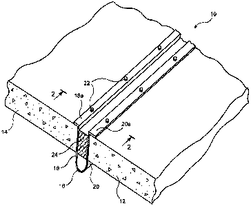
FIG. 1 is a pictorial representation, partially cut away, illustrating the
installation of the expansion joint of the invention between adjacent building
panels;
FIG. 2 is a cross-section taken along the lines 2-2 of FIG. 1;
FIGS. 3A, B and C are cross-sectional views similar to FIG. 2 showing
the expansion joint as installed, under compression and when expanded,
respectively;
and
FIG. 4 is a cross-sectional view, similar to FIG. 2, showing a
modification of the expansion joint of the invention.
DETAILED DESCRIPTION OF THE INVENTION
Referring now to the drawings, FIGS. 1 and 2 illustrate the novel
expansion joint of the invention as installed between adjacent building panels
of a
structure. In this example, the building panels are shown as adjacent
horizontal
concrete slabs 12, 14 forming part of a floor of a structure, but it will be
understood
that the invention is applicable to adjacent vertical wall panels as well.
The joint structure 10 comprises a heat shield or drape 16 made of 2
mil (0.002 inch) thick impermeable stainless steel foil, formed into a
longitudinally
extending generally U-shaped trough, the opposite legs of which are indicated
at 18
and 20. The legs 18, 20 are bent along their longitudinal edges at 90°
to form flanges
18a and 20a. The drape 16 can be either metallic or woven ceramic. The drape
16
can also be woven from fire retardant fabric and should be flexible. When
installed
between slabs 12 and 14, the flanges overlay the upper surfaces of the
adjacent slabs
and bolts or other fasteners 22 secure the drape to the slabs. These fasteners
may also
serve to secure rails of a raised floor system installed over the slabs.
Between legs 18 and 20 of the U-shaped drape 16 is inserted an
elongated mat 24 of expandable fire resistant material, such as the Ultra
Block
discussed above. The material is compressible at nominal (room) temperatures
and is
partially compressed when inserted between the legs 18, 20 of the drape, as
shown in
FIG. 3A. This permits the mat to be compressed when the adjacent slabs 12, 14
expand at elevated temperatures, as shown in FIG 3B, and to expand at cooler
temperatures, as seen in FIG. 3C, without separating from the inner surfaces
of legs
18, 20. No sealants or other inserts are required to maintain the joint
structure
between the slabs. The material is inherently resilient and, when installed
under
-3-

CA 02544830 2006-05-04
WO 2005/047610 PCT/US2004/033390
compression, will successfully cycle plus or minus 50% or more of the nominal
joint
width. This compression feature also serves to hold the legs 18, 20 tight
against the
concrete slabs 12 and 14, which in effect prevents hot gases from breaching
the
system.
As seen in the drawings, a space is left between the bottom of mat 24
and the curved bottom of drape 16. This allows the drape to flex without
impediment
during expansion and contraction of the joint. A small amount of adhesive may
be
applied to secure the mat to the drape after the mat is inserted.
The stainless steel foil drape 16 is impermeable to gases and thus
forms an impenetrable fire and smoke barrier between the adjacent slabs. This
prevents the occurrence of the so-called chimney effect, which would otherwise
enable heat and fire to rise up through the floor and enter the space above
the slabs.
This increases the fire rating and safety of the structure and aids in
compliance with
Underwriters Laboratory standards.
It will be seen that the expansion joint of the invention is readily
adaptable to different slab thicknesses and separation, because of the
flexibility of the
foil drape and the compressibility of the mat material. Moreover, the joint is
assembled and installed on site, with minimal off site preparation required.
Where the nominal separation between slabs is greater than 3 inches, it
may be desirable to supplement the stiffness and fire resistance of the drape.
This
may be accomplished, as illustrated in FIG. 4, by adding a liner 28 to the
inside
surface of the drape. Liner 28 may be made of a flexible insulating material
inserted
within the drape 16 before insertion of mat 24. Liner 28 may be made of
ceramic
fiber blanket, for example, or other flexible insulation materials, and may be
thicker
along the bottom of drape 16 than between the legs 18, 20 and mat 24, as shown
in
FIG. 4.
Although the invention has been described above as applied to
horizontal concrete slabs in a building structure, it will be apparent that it
has equal
utility between vertical wall panels of a building, whether such panels are
concrete
slabs or wallboard-covered framing.
Moreover, while the heat and fire resistance characteristics of the
inventions have been discussed above, it will be realized that the enhanced
flexibility
of the inventive expansion joint enables it to retain its integrity when the
adjacent
-4-

CA 02544830 2006-05-04
WO 2005/047610 PCT/US2004/033390
panels are moved as a result of seismic activity, as well. This is yet another
advantage
of the invention not found in prior art devices.
Although the invention has been described above in connection with its
preferred embodiments, it will be appreciated that other embodiments and
variations
of the invention will occur to those skilled in the art. Accordingly, it is
understood
that the scope of the invention is to be limited only as set forth in the
appended
claims.
-5-

Representative Drawing
A single figure which represents the drawing illustrating the invention.
Administrative Status

2024-08-01:As part of the Next Generation Patents (NGP) transition, the Canadian Patents Database (CPD) now contains a more detailed Event History, which replicates the Event Log of our new back-office solution.

Please note that "Inactive:" events refers to events no longer in use in our new back-office solution.

For a clearer understanding of the status of the application/patent presented on this page, the site Disclaimer , as well as the definitions for Patent , Event History , Maintenance Fee  and Payment History  should be consulted.

Event History

Description Date
Application Not Reinstated by Deadline 2010-10-07
Time Limit for Reversal Expired 2010-10-07
Deemed Abandoned - Failure to Respond to Maintenance Fee Notice 2009-10-07
Letter Sent 2008-11-21
Request for Examination Received 2008-10-09
All Requirements for Examination Determined Compliant 2008-10-09
Request for Examination Requirements Determined Compliant 2008-10-09
Inactive: Cover page published 2006-07-21
Letter Sent 2006-07-13
Inactive: Notice - National entry - No RFE 2006-07-13
Application Received - PCT 2006-05-31
National Entry Requirements Determined Compliant 2006-05-04
Application Published (Open to Public Inspection) 2005-05-26

Abandonment History

Abandonment Date Reason Reinstatement Date
2009-10-07

Maintenance Fee

The last payment was received on 2008-09-30

Note : If the full payment has not been received on or before the date indicated, a further fee may be required which may be one of the following

  • the reinstatement fee;
  • the late payment fee; or
  • additional fee to reverse deemed expiry.

Please refer to the CIPO Patent Fees web page to see all current fee amounts.

Fee History

Fee Type Anniversary Year Due Date Paid Date
MF (application, 2nd anniv.) - standard 02 2006-10-10 2006-05-04
Registration of a document 2006-05-04
Basic national fee - standard 2006-05-04
MF (application, 3rd anniv.) - standard 03 2007-10-09 2007-09-25
MF (application, 4th anniv.) - standard 04 2008-10-07 2008-09-30
Request for examination - standard 2008-10-09
Owners on Record

Note: Records showing the ownership history in alphabetical order.

Current Owners on Record
E.M.E.H., INC.
Past Owners on Record
ROGER BARR
Past Owners that do not appear in the "Owners on Record" listing will appear in other documentation within the application.
Documents

To view selected files, please enter reCAPTCHA code :


To view images, click a link in the Document Description column. To download the documents, select one or more checkboxes in the first column and then click the "Download Selected in PDF format (Zip Archive)" or the "Download Selected as Single PDF" button.

List of published and non-published patent-specific documents on the CPD .

If you have any difficulty accessing content, you can call the Client Service Centre at 1-866-997-1936 or send them an e-mail at CIPO Client Service Centre.


Document
Description 
Date
(yyyy-mm-dd) 
Number of pages   Size of Image (KB) 
Claims 2006-05-04 3 109
Abstract 2006-05-04 2 67
Drawings 2006-05-04 4 66
Description 2006-05-04 5 247
Representative drawing 2006-07-20 1 10
Cover Page 2006-07-21 1 40
Claims 2006-05-05 3 108
Notice of National Entry 2006-07-13 1 192
Courtesy - Certificate of registration (related document(s)) 2006-07-13 1 105
Acknowledgement of Request for Examination 2008-11-21 1 176
Courtesy - Abandonment Letter (Maintenance Fee) 2009-12-02 1 172
PCT 2006-05-04 1 55
Fees 2007-09-25 1 50
Fees 2008-09-30 1 38