Sélection de la langue

Search

Sommaire du brevet 2544830 

Énoncé de désistement de responsabilité concernant l'information provenant de tiers

Une partie des informations de ce site Web a été fournie par des sources externes. Le gouvernement du Canada n'assume aucune responsabilité concernant la précision, l'actualité ou la fiabilité des informations fournies par les sources externes. Les utilisateurs qui désirent employer cette information devraient consulter directement la source des informations. Le contenu fourni par les sources externes n'est pas assujetti aux exigences sur les langues officielles, la protection des renseignements personnels et l'accessibilité.

Disponibilité de l'Abrégé et des Revendications

L'apparition de différences dans le texte et l'image des Revendications et de l'Abrégé dépend du moment auquel le document est publié. Les textes des Revendications et de l'Abrégé sont affichés :

  • lorsque la demande peut être examinée par le public;
  • lorsque le brevet est émis (délivrance).
(12) Demande de brevet: (11) CA 2544830
(54) Titre français: JOINT COUPE FEU POUR PANNEAUX DE CONSTRUCTION
(54) Titre anglais: FIRE BARRIER SYSTEM FOR BUILDING PANELS
Statut: Réputée abandonnée et au-delà du délai pour le rétablissement - en attente de la réponse à l’avis de communication rejetée
Données bibliographiques
(51) Classification internationale des brevets (CIB):
  • E04C 3/00 (2006.01)
(72) Inventeurs :
  • BARR, ROGER (Etats-Unis d'Amérique)
(73) Titulaires :
  • E.M.E.H., INC.
(71) Demandeurs :
  • E.M.E.H., INC. (Etats-Unis d'Amérique)
(74) Agent: SMART & BIGGAR LP
(74) Co-agent:
(45) Délivré:
(86) Date de dépôt PCT: 2004-10-07
(87) Mise à la disponibilité du public: 2005-05-26
Requête d'examen: 2008-10-09
Licence disponible: S.O.
Cédé au domaine public: S.O.
(25) Langue des documents déposés: Anglais

Traité de coopération en matière de brevets (PCT): Oui
(86) Numéro de la demande PCT: PCT/US2004/033390
(87) Numéro de publication internationale PCT: WO 2005047610
(85) Entrée nationale: 2006-05-04

(30) Données de priorité de la demande:
Numéro de la demande Pays / territoire Date
10/701,289 (Etats-Unis d'Amérique) 2003-11-04

Abrégés

Abrégé français

L'invention porte sur un joint de dilatation coupe feu pour panneaux de construction tels que des dalles de béton consistant en une tôle en U, d'un matériau flexible, résistant au feu et imperméable tel que de l'acier inoxydable, dont les bras opposés se fixent respectivement aux deux dalles contiguës, et entre lesquels on dispose un bourrage d'un matériau expansible et résistant au feu. L'imperméabilité et la flexibilité de la tôle, liées à la propriété isolante du bourrage, donnent un joint coupe feu économique et efficace pouvant en outre absorber les déplacements sismiques.


Abrégé anglais


An expansion joint for building panels, such as concrete floor slabs,
comprises a U-shaped drape of a flexible, fire-resistant, impermeable material
such as stainless steel foil. The opposite legs of the U-shaped drape are
fastened between respective adjacent slabs and a mat of expandable fire-
resistant material inserted within the U-shaped drape between the slabs. The
impermeability and flexibility of the drape, coupled with the insulating
property of the mat provide an inexpensive, effective fire seal between
building panels that can also accommodate seismic displacement.

Revendications

Note : Les revendications sont présentées dans la langue officielle dans laquelle elles ont été soumises.


I CLAIM:
1. A fire-barrier expansion joint for insertion between adjacent building
panels comprising:
a strip of flexible heat-resistant impermeable sheet material shaped to
form an elongated trough with a generally U-shaped cross-section, and
an elongated mat of expandable fire-resistant material disposed within
said trough.
2. The expansion joint of claim 1 wherein the upper edge of each side of
said trough is bent outwardly at approximately a right angle to said side.
3. The expansion joint of claim 1 wherein said sheet material is stainless
steel foil.
4. The expansion joint of claim 3 further comprising a layer of insulating
material lining said trough.
5. The expansion joint of claim 1 wherein said mat comprises a
combination of non-combustible fibrous material and heat expandable particles.
6. The expansion joint of claim 1 wherein said mat disposed within said
trough is under compression.
7. The expansion joint of claim 6 wherein said mat under compression
seals said trough to said adjacent building panels.
8. The expansion joint of claim 6 wherein said mat under compression
holds said expansion joint against said adjacent building panels.
9. The expansion joint of claim 6 wherein said mat under compression
locks said expansion joint to said adjacent building panels.
10. The expansion joint of claim 1 wherein said mat disposed within said
trough is configured to remain under compression.
11. The expansion joint of claim 1 wherein said mat disposed within said
trough is configured to remain under compression when the distance between the
-6-

adjacent building panels varies up to 50% from the distance between the
adjacent
building panels when said mat was inserted within said trough.
12. A method for inserting a fire-barrier expansion joint between adjacent
building panels comprising:
(a) inserting between said adjacent building panels a strip of
flexible heat-resistant impermeable sheet material shaped to form an elongated
trough
with a generally U-shaped cross-section, and
(b) inserting an elongated mat of expandable fire-resistant material
within said trough.
13. The method of claim 12, further comprising inserting under
compression said elongated mat of expandable fire-resistant material within
said
trough.
14. The method of claim 13, further comprising inserting under sufficient
compression said elongated mat of expandable fire resistant material within
said
trough so that said mat remains under compression when the distance between
the
adjacent building panels varies up to 50% from the distance between the
adjacent
building panels when said mat was inserted within said trough.
15. The method of claim 13, further comprising inserting under sufficient
compression said elongated mat of expandable fire resistant material within
said
trough so that said mat remains under compression when the distance between
the
adjacent building panels varies up to 50% from the distance between the
adjacent
building panels when said mat was inserted within said trough and said trough
remains sealed to said adjacent building panels.
16. The method of claim 13, further comprising inserting under sufficient
compression said elongated mat of expandable fire resistant material within
said
trough so that said mat remains under compression when the distance between
the
adjacent building panels varies up to 50% from the distance between the
adjacent
building panels when said mat was inserted within said trough and said mat
under
compression holds said expansion joint against said adjacent building panels.
-7-

17. The method of claim 13, further comprising inserting under sufficient
compression said elongated mat of expandable fire resistant material within
said
trough so that said mat remains under compression when the distance between
the
adjacent building panels varies up to 50% from the distance between the
adjacent
building panels when said mat was inserted within said trough and said mat
under
compression locks said expansion joint to said adjacent building panels.
-8-

Description

Note : Les descriptions sont présentées dans la langue officielle dans laquelle elles ont été soumises.

CA 02544830 2006-05-04
WO 2005/047610 PCT/US2004/033390
FIRE BARRIER SYSTEM FOR BUILDING PANELS
SPECIFICATION
CROSS-REFERENCE TO RELATED APPLICATIONS
This application claims priority to U.S. Serial No. 101701,289 filed
November 4, 2003 entitled "Fire Barrier System for Building Panels"
FIELD OF THE INVENTION
The present invention relates generally to expansion joints for building
panels and more particularly to expansion joints for building panels such as
concrete
floor slabs that provide the necessary flexibility for expansion and
contraction and at
the same time, block fire and heat flow between adjacent panels.
BACKGROUND OF THE INVENTION
It is generally understood that in building construction, it is necessary
to provide expansion joints between abutting floor or wall panels to allow for
expansion and contraction of the material under varying temperatures. In
concrete
construction, such joints typically comprise a strip of a relatively soft
material
interposed between the edges of abutting slabs of concrete when poured. Over
time,
the joint material tends to dry out and pull away from the opposed concrete
surfaces.
While this effect poses little problem in concrete slabs poured on grade, it
is a matter
of significant concern when the slabs constitute the floors of a multilevel
structure.
Not only would the joint material tend to separate from the slabs over time,
it could
even fall out completely during periods of extreme contraction. In either
event, this
would leave gaps between adjacent slabs that would act as chimneys in the
event of a
fire in the structure; thereby enabling the fire to rapidly spread to upper
levels.
In one known form of expansion joint, described in U.S. Patent No.
4,756,945, a blanket of non-combustible, heat-expansible material is folded
over on
itself to form a barrier strip and inserted between adj acent building panels.
The strip,
comprising inter alia, a combination of non-combustible fibrous material and
heat
expandable particles, is secured between the panels by backer rods pressed in
on
-1-

CA 02544830 2006-05-04
WO 2005/047610 PCT/US2004/033390
either side of the strip. Elastomeric sealing material is then added to cover
the backer
rods.
While the material described in the above-mentioned patent,
manufactured and sold by Backer Rod Manufacturing, Inc. of Denver, Colorado,
under the name Ultra Block, has suitable heat-resistance and expansion
characteristics
for building applications, the manner disclosed in the patent for securing the
material
between building panels is relatively complex and suffers the disadvantage
that the
sealing rods and elastomer used to retain the material in place are subject to
drying
over time and dropping out.
In another type of expansion joint, manufactured by the Watson
Bowman Acme Corp. of Amherst, NY and marketed under the names Wabo Fire Flex
and Wabo Flame Guard, heat-resistant material is formed into a U-shaped trough
and
secured between adjacent panels by sheet metal strips along the edges of each
leg of
the U. The material is otherwise unsupported or protected against accidental
damage.
A similar fire barrier is manufactured by MM Systems and sold under the name
PYRO-FLEX.
SL~yIMARY OF THE INVENTION
The object of the present invention is to provide a fire-resistant joint
for building construction that overcomes the disadvantages of prior art
expedients.
In accordance with the invention, this object is achieved with a two-
piece joint system comprising a strip of fire-resistant, flexible sheet
material formed
into a U-shaped trough or drape and an elongated mat of expandable fire-
resistant mat
retained within the drape. The edges of the flexible drape are bent outwardly
to
overlay the surfaces of the adjacent building panels and secured thereto by
suitable
fasteners. Little or no adhesives and no sealants are required to secure the
joint in
place and the impervious nature of the drape guards against the chimney
effect. The
savings in installation time and cost of the invention provides a further
significant
advantage over prior art systems.
BRIEF DESCRIPTION OF THE DRAWINGS
The foregoing objects, features and advantages of the invention will
become apparent from the following detailed description thereof, taken in
conjunction
with the appended drawings, in which:
-2-

CA 02544830 2006-05-04
WO 2005/047610 PCT/US2004/033390
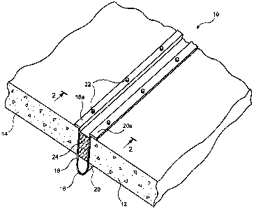
FIG. 1 is a pictorial representation, partially cut away, illustrating the
installation of the expansion joint of the invention between adjacent building
panels;
FIG. 2 is a cross-section taken along the lines 2-2 of FIG. 1;
FIGS. 3A, B and C are cross-sectional views similar to FIG. 2 showing
the expansion joint as installed, under compression and when expanded,
respectively;
and
FIG. 4 is a cross-sectional view, similar to FIG. 2, showing a
modification of the expansion joint of the invention.
DETAILED DESCRIPTION OF THE INVENTION
Referring now to the drawings, FIGS. 1 and 2 illustrate the novel
expansion joint of the invention as installed between adjacent building panels
of a
structure. In this example, the building panels are shown as adjacent
horizontal
concrete slabs 12, 14 forming part of a floor of a structure, but it will be
understood
that the invention is applicable to adjacent vertical wall panels as well.
The joint structure 10 comprises a heat shield or drape 16 made of 2
mil (0.002 inch) thick impermeable stainless steel foil, formed into a
longitudinally
extending generally U-shaped trough, the opposite legs of which are indicated
at 18
and 20. The legs 18, 20 are bent along their longitudinal edges at 90°
to form flanges
18a and 20a. The drape 16 can be either metallic or woven ceramic. The drape
16
can also be woven from fire retardant fabric and should be flexible. When
installed
between slabs 12 and 14, the flanges overlay the upper surfaces of the
adjacent slabs
and bolts or other fasteners 22 secure the drape to the slabs. These fasteners
may also
serve to secure rails of a raised floor system installed over the slabs.
Between legs 18 and 20 of the U-shaped drape 16 is inserted an
elongated mat 24 of expandable fire resistant material, such as the Ultra
Block
discussed above. The material is compressible at nominal (room) temperatures
and is
partially compressed when inserted between the legs 18, 20 of the drape, as
shown in
FIG. 3A. This permits the mat to be compressed when the adjacent slabs 12, 14
expand at elevated temperatures, as shown in FIG 3B, and to expand at cooler
temperatures, as seen in FIG. 3C, without separating from the inner surfaces
of legs
18, 20. No sealants or other inserts are required to maintain the joint
structure
between the slabs. The material is inherently resilient and, when installed
under
-3-

CA 02544830 2006-05-04
WO 2005/047610 PCT/US2004/033390
compression, will successfully cycle plus or minus 50% or more of the nominal
joint
width. This compression feature also serves to hold the legs 18, 20 tight
against the
concrete slabs 12 and 14, which in effect prevents hot gases from breaching
the
system.
As seen in the drawings, a space is left between the bottom of mat 24
and the curved bottom of drape 16. This allows the drape to flex without
impediment
during expansion and contraction of the joint. A small amount of adhesive may
be
applied to secure the mat to the drape after the mat is inserted.
The stainless steel foil drape 16 is impermeable to gases and thus
forms an impenetrable fire and smoke barrier between the adjacent slabs. This
prevents the occurrence of the so-called chimney effect, which would otherwise
enable heat and fire to rise up through the floor and enter the space above
the slabs.
This increases the fire rating and safety of the structure and aids in
compliance with
Underwriters Laboratory standards.
It will be seen that the expansion joint of the invention is readily
adaptable to different slab thicknesses and separation, because of the
flexibility of the
foil drape and the compressibility of the mat material. Moreover, the joint is
assembled and installed on site, with minimal off site preparation required.
Where the nominal separation between slabs is greater than 3 inches, it
may be desirable to supplement the stiffness and fire resistance of the drape.
This
may be accomplished, as illustrated in FIG. 4, by adding a liner 28 to the
inside
surface of the drape. Liner 28 may be made of a flexible insulating material
inserted
within the drape 16 before insertion of mat 24. Liner 28 may be made of
ceramic
fiber blanket, for example, or other flexible insulation materials, and may be
thicker
along the bottom of drape 16 than between the legs 18, 20 and mat 24, as shown
in
FIG. 4.
Although the invention has been described above as applied to
horizontal concrete slabs in a building structure, it will be apparent that it
has equal
utility between vertical wall panels of a building, whether such panels are
concrete
slabs or wallboard-covered framing.
Moreover, while the heat and fire resistance characteristics of the
inventions have been discussed above, it will be realized that the enhanced
flexibility
of the inventive expansion joint enables it to retain its integrity when the
adjacent
-4-

CA 02544830 2006-05-04
WO 2005/047610 PCT/US2004/033390
panels are moved as a result of seismic activity, as well. This is yet another
advantage
of the invention not found in prior art devices.
Although the invention has been described above in connection with its
preferred embodiments, it will be appreciated that other embodiments and
variations
of the invention will occur to those skilled in the art. Accordingly, it is
understood
that the scope of the invention is to be limited only as set forth in the
appended
claims.
-5-

Dessin représentatif
Une figure unique qui représente un dessin illustrant l'invention.
États administratifs

2024-08-01 : Dans le cadre de la transition vers les Brevets de nouvelle génération (BNG), la base de données sur les brevets canadiens (BDBC) contient désormais un Historique d'événement plus détaillé, qui reproduit le Journal des événements de notre nouvelle solution interne.

Veuillez noter que les événements débutant par « Inactive : » se réfèrent à des événements qui ne sont plus utilisés dans notre nouvelle solution interne.

Pour une meilleure compréhension de l'état de la demande ou brevet qui figure sur cette page, la rubrique Mise en garde , et les descriptions de Brevet , Historique d'événement , Taxes périodiques et Historique des paiements devraient être consultées.

Historique d'événement

Description Date
Demande non rétablie avant l'échéance 2010-10-07
Le délai pour l'annulation est expiré 2010-10-07
Réputée abandonnée - omission de répondre à un avis sur les taxes pour le maintien en état 2009-10-07
Lettre envoyée 2008-11-21
Requête d'examen reçue 2008-10-09
Toutes les exigences pour l'examen - jugée conforme 2008-10-09
Exigences pour une requête d'examen - jugée conforme 2008-10-09
Inactive : Page couverture publiée 2006-07-21
Lettre envoyée 2006-07-13
Inactive : Notice - Entrée phase nat. - Pas de RE 2006-07-13
Demande reçue - PCT 2006-05-31
Exigences pour l'entrée dans la phase nationale - jugée conforme 2006-05-04
Demande publiée (accessible au public) 2005-05-26

Historique d'abandonnement

Date d'abandonnement Raison Date de rétablissement
2009-10-07

Taxes périodiques

Le dernier paiement a été reçu le 2008-09-30

Avis : Si le paiement en totalité n'a pas été reçu au plus tard à la date indiquée, une taxe supplémentaire peut être imposée, soit une des taxes suivantes :

  • taxe de rétablissement ;
  • taxe pour paiement en souffrance ; ou
  • taxe additionnelle pour le renversement d'une péremption réputée.

Veuillez vous référer à la page web des taxes sur les brevets de l'OPIC pour voir tous les montants actuels des taxes.

Historique des taxes

Type de taxes Anniversaire Échéance Date payée
TM (demande, 2e anniv.) - générale 02 2006-10-10 2006-05-04
Enregistrement d'un document 2006-05-04
Taxe nationale de base - générale 2006-05-04
TM (demande, 3e anniv.) - générale 03 2007-10-09 2007-09-25
TM (demande, 4e anniv.) - générale 04 2008-10-07 2008-09-30
Requête d'examen - générale 2008-10-09
Titulaires au dossier

Les titulaires actuels et antérieures au dossier sont affichés en ordre alphabétique.

Titulaires actuels au dossier
E.M.E.H., INC.
Titulaires antérieures au dossier
ROGER BARR
Les propriétaires antérieurs qui ne figurent pas dans la liste des « Propriétaires au dossier » apparaîtront dans d'autres documents au dossier.
Documents

Pour visionner les fichiers sélectionnés, entrer le code reCAPTCHA :


Pour visualiser une image, cliquer sur un lien dans la colonne description du document. Pour télécharger l'image (les images), cliquer l'une ou plusieurs cases à cocher dans la première colonne et ensuite cliquer sur le bouton "Télécharger sélection en format PDF (archive Zip)" ou le bouton "Télécharger sélection (en un fichier PDF fusionné)".

Liste des documents de brevet publiés et non publiés sur la BDBC .

Si vous avez des difficultés à accéder au contenu, veuillez communiquer avec le Centre de services à la clientèle au 1-866-997-1936, ou envoyer un courriel au Centre de service à la clientèle de l'OPIC.


Description du
Document 
Date
(aaaa-mm-jj) 
Nombre de pages   Taille de l'image (Ko) 
Revendications 2006-05-04 3 109
Abrégé 2006-05-04 2 67
Dessins 2006-05-04 4 66
Description 2006-05-04 5 247
Dessin représentatif 2006-07-20 1 10
Page couverture 2006-07-21 1 40
Revendications 2006-05-05 3 108
Avis d'entree dans la phase nationale 2006-07-13 1 192
Courtoisie - Certificat d'enregistrement (document(s) connexe(s)) 2006-07-13 1 105
Accusé de réception de la requête d'examen 2008-11-21 1 176
Courtoisie - Lettre d'abandon (taxe de maintien en état) 2009-12-02 1 172
PCT 2006-05-04 1 55
Taxes 2007-09-25 1 50
Taxes 2008-09-30 1 38