Note: Descriptions are shown in the official language in which they were submitted.
CA 02544866 2006-04-25
FLUID ANALYSIS METHOD AND APPARATUS
Background of the Invention
1. Field of the Invention
The present invention relates to techniques for performing formation
evaluation of a
subterranean formation by a down hole tool positioned in a well bore
penetrating the
subterranean formation. More particularly, but not by way of limitation, the
present
invention relates to techniques for making measurements of formation fluids.
2. Background of the Related Art
Well bores are drilled to locate and produce hydrocarbons. A down hole
drilling tool
with a bit at an end thereof is advanced into the ground to form a well bore.
As the drilling
tool is advanced, a drilling mud is pumped through the drilling tool and out
the drill bit to
cool the drilling tool and carry away cuttings. The drilling mud additionally
forms a mud
cake that lines the well bore.
During the drilling operation, it is desirable to perform various evaluations
of the
formations penetrated by the well bore. In some cases, the drilling tool may
be removed and
a wire line tool may be deployed into the well bore to test and/or sample the
formation. In
other cases, the drilling tool may be provided with devices to test and/or
sample the
surrounding formation and the drilling tool may be used to perform the testing
or sampling.
These samples or tests may be used, for example, to locate valuable
hydrocarbons.
Formation evaluation often requires that fluid from the formation be drawn
into the
down hole tool for testing and/or sampling. Various devices, such as probes,
are extended
from the down hole tool to establish fluid communication with the formation
surrounding the
well bore and to draw fluid into the down hole tool. A typical probe is a
circular element
extended from the down hole tool and positioned against the sidewall of the
well bore. A
rubber packer at the end of the probe is used to create a seal with the wall
of the well bore.
1
CA 02544866 2006-04-25
Another device used to form a seal with the well bore is referred to as a dual
packer. With a
dual packer, two elastomeric rings expand radially about the tool to isolate a
portion of the
well bore there between. The rings form a seal with the well bore wall and
permit fluid to be
drawn into the isolated portion of the well bore and into an inlet in the down
hole tool.
The mud cake lining the well bore is often useful in assisting the probe
and/or dual
packers in making the seal with the well bore wall. Once the seal is made,
fluid from the
formation is drawn into the down hole tool through an inlet by lowering the
pressure in the
down hole tool. Examples of probes and/or packers used in down hole tools are
described in
U.S. Patent Nos. 6,301,959; 4,860,581; 4,936,139; 6,585,045; 6,609,568 and
6,719,049 and
U.S. Patent Application No. 2004/0000433.
Formation evaluation is typically performed on fluids drawn into the down hole
tool.
Techniques currently exist for performing various measurements, pretests
and/or sample
collection of fluids that enter the down hole tool.
Fluid passing through the down hole tool may be tested to determine various
down
hole parameters or properties. Various properties of hydrocarbon reservoir
fluids, such as
viscosity, density and phase behavior of the fluid at reservoir conditions,
may be used to
evaluate potential reserves, determine flow in porous media and design
completion,
separation, treating, and metering systems, among others.
Additionally, samples of the fluid may be collected in the down hole tool and
retrieved at the surface. The down hole tool stores the formation fluid in one
or more sample
chambers or bottles and retrieves the bottles to the surface while keeping the
formation fluid
pressurized. An example of this type of sampling is described in US Patent No.
6688390.
Such samples are sometimes referred to as live-fluids. These fluids may then
be sent to an
appropriate laboratory for further analysis. Typical fluid analysis or
characterization may
include, for example, composition analysis, fluid properties and phase
behavior. In some
2
CA 02544866 2006-04-25
cases, such analysis may also be made at the well site surface using a
transportable lab
system
Techniques have been developed to perform surface testing of the live-fluids.
Many
fluid measurements can require on the order of an hour or more time. For
example, with
phase behavior analysis or determination, the fluid begins as a single phase,
liquid or gas.
The temperature is held constant. The volume is expanded in a series of small
steps. Before
the next step in volume is taken, the pressure must be stable. In order to
accelerate the time
required to stabilize the pressure, the fluid is actively mixed. Such mixing
typically involves
stirring, churning, shearing, vibrating and/or otherwise transporting the
fluid volume. During
the volume expansion process or steps, optical technologies are used to detect
the presence of
a separate phase. For example, a 2 micron resolution high pressure camera may
be used to
take pictures, via an optical window, and a measurement of light absorbance
may be made
using Near Infra Red (NIR).
During sampling, reservoir fluid may exhibit a variety of phase transitions.
Often
these transitions are the result of cooling, pressure depletion and/or
compositional changes
that occur as the fluid is drawn into the tool and/or retrieved to the
surface. The
characterization of fluid phase behavior is key to the planning and
optimization of field
development and production. Changes of temperature (T) and pressure (P) of the
formation
fluid often lead to multi-phase separation (e.g., liquid-vapor, liquid-solid,
liquid-liquid,
vapor-liquid, etc.), and phase recombination. Similarly, a single-phase gas
typically has an
envelope at which a liquid phase separates, known as the dew point. These
changes can
affect the measurements taken during formation evaluation. Moreover, there is
a significant
delay in time between sampling and testing at the surface or offsite
laboratories.
It is, therefore, desirable to provide techniques capable of performing
formation
evaluation of fluid that is representative of fluid in the formation. It is
further desirable that
3
CA 02544866 2006-04-25
such techniques provide accurate and real-time measurements. Such formation
evaluation
would need to operate within size and time constraints of well bore
operations, and
preferably are performed down hole. It is to such a fluid analysis assembly
capable of
effecting such formation evaluation that the present invention is directed.
Summary of the Invention
In at least one aspect, the present invention relates to a fluid analysis
assembly for
analyzing a fluid. The fluid analysis assembly includes a chamber, a fluid
movement device,
a pressurization assembly and at least one sensor. The chamber defines an
evaluation cavity
for receiving the fluid. The fluid movement device has a force medium applying
force to the
fluid to cause the fluid to move within the cavity. The pressurization
assembly changes the
pressure of the fluid in a continuous manner. The at least one sensor
communicates with the
fluid for sensing at least one parameter of the fluid while the pressure of
the fluid is changing
in the continuous manner.
In one version, the chamber is characterized as a flow line, such as a re-
circulating
loop. In another version, the chamber includes a flow line, a bypass loop
communicating
with the flow line and defining the evaluation cavity, and at least one valve
positioned
between the flow line and the evaluation cavity of the bypass loop for
selectively diverting
fluid into the evaluation cavity of the bypass loop from the flow line.
In yet another version, the fluid movement device includes a pump. Optionally,
the
fluid movement device includes a mixing element positioned within the
evaluation cavity and
forming a vortex within the fluid. In this version, at least one of the
sensors is desirably
positioned within the vortex.
In yet a further version, the fluid movement device and the pressurization
assembly
are integrally formed and collectively comprise a first housing, a second
housing, a first
piston and a second piston. The first housing defines a first cavity
communicating with the
4
CA 02544866 2006-04-25
evaluation cavity of the chamber. The second housing defines a second cavity
communicating with the evaluation cavity of the chamber. The first cavity has
a cross-
sectional area larger than a cross-sectional area of the second cavity. The
first piston is
positioned within the first cavity and is movable within the first cavity. The
second piston is
positioned with the second cavity and is movable within the second cavity. The
movement of
the first and second pistons is synchronized to simultaneously cause movement
of the fluid
and a change in the pressure within the chamber.
In a version designed to detect phase changes of the fluid, the at least one
sensor
desirably includes a pressure sensor, a temperature sensor, and a bubble-point
sensor. The
pressure sensor reads the pressure within the evaluation cavity of the
chamber. The
temperature sensor reads the temperature of the fluid within the evaluation
cavity. The
bubble-point sensor detects the formation of bubbles within the fluid.
In another aspect, the present invention relates to a down hole tool
positionable in a
well bore having a wall and penetrating a subterranean formation. The
formation has a fluid
therein. The down hole tool includes a housing, a fluid communication device,
and a fluid
analysis assembly. The fluid communication device is extendable from the
housing for
sealing engagement with the wall of the well bore. The fluid communication
device has at
least one inlet for receiving the fluid from the formation. The fluid analysis
assembly is
positioned within the housing for analyzing the fluid. The fluid analysis
assembly includes a
chamber, a fluid movement device, a pressurization assembly and at least one
sensor. The
chamber defines an evaluation cavity for receiving the fluid from the fluid
communication
device. The fluid movement device has a force medium applying force to the
fluid to cause
the fluid to move within the evaluation cavity. The pressurization assembly
changes the
pressure of the fluid. The at least one sensor communicates with the fluid for
sensing at least
one parameter of the fluid. The fluid analysis assembly can be any of the
versions of the
CA 02544866 2009-02-09
79350-200
fluid analysis assembly described above.
In one version, the fluid communication device includes at least two inlets
with one of
the inlets receiving virgin fluid from the formation. In this version, the
down hole tool
further comprises a flow line receiving the virgin fluid from one of the
inlets of the fluid
communication device and conveying the virgin fluid into the evaluation
cavity.
The present invention also relates to a method for measuring a parameter of an
unknown fluid within a well bore penetrating a formation having the fluid
therein. In the
method, a fluid communication device of the down hole tool is positioned in
sealing
engagement with a wall of the well bore. Fluid is drawn out of the formation
and into an
evaluation cavity within the down hole tool. The fluid is moved within the
evaluation cavity,
and data is sampled while the fluid is being moved within the evaluation
cavity.
In one version of the method, pressure is continuously changed within the
evaluation
cavity while the data is being sampled.
In another version of the method, a bubble point of the fluid is determined
based on
the sampled data.
In yet another version of the method, the evaluation cavity is defined further
as a
bypass loop from a main flow line, and wherein the method further comprises
the steps of
diverting fluid from the main flow line into a separate evaluation cavity,
recirculating the
diverted fluid within the separate evaluation cavity, and sampling data of the
diverted fluid
within the separate evaluation cavity while the diverted fluid is being
recirculated.
In a further version, fluids trapped in separate evaluation cavities can be
mixed, and
then the mixed fluid can be recirculated. Data is then sampled of the mixed
fluid while the
mixed fluid is being recirculated.
In one aspect, the fluid communication device is a dual-packer, and the
unknown
fluid is a virgin fluid.
6
CA 02544866 2009-02-09
79350-200
The present invention also relates to a fluid
analysis assembly for analyzing a fluid, the fluid analysis
assembly comprising: a chamber defining an evaluation cavity
for receiving the fluid; a fluid movement device having a
force medium applying force to the fluid to cause the fluid
to move within the cavity; a pressurization assembly
changing the pressure of the fluid in a continuous manner,
wherein the assembly is adapted to change the pressure
independently of the fluid movement device; and at least one
sensor communicating with the fluid for sensing at least one
parameter of the fluid while the pressure of the fluid is
changing in the continuous manner; wherein the chamber is
characterized as a flow line.
The present invention further relates to a down
hole tool positionable in a well bore having a wall and
penetrating a subterranean formation, the formation having a
fluid therein, the down hole tool comprising: a housing; a
fluid communication device extendable from the housing for
sealing engagement with the wall of the well bore, the fluid
communication device having at least one inlet for receiving
the fluid from the formation; and a fluid analysis assembly
positioned within the housing for analyzing the fluid, the
fluid analysis assembly comprising: a chamber defining an
evaluation cavity for receiving the fluid from the fluid
communication device; a fluid movement device having a force
medium applying force to the fluid to cause the fluid to
move within the evaluation cavity; a pressurization assembly
changing the pressure of the fluid, wherein the assembly is
able to change the pressure independently of the fluid
movement device; and at least one sensor communicating with
the fluid for sensing at least one parameter of the fluid.
6a
CA 02544866 2009-02-09
'79350-200
The present invention still further relates to a
method for measuring a parameter of an unknown fluid within
a well bore penetrating a formation having the fluid
therein, comprising the steps of: positioning a fluid
communication device of the down hole tool in sealing
engagement with a wall of the well bore; drawing fluid out
of the formation and into an evaluation cavity within the
down hole tool; moving the fluid within the evaluation
cavity with a fluid movement device; changing a pressure of
the fluid with a pressurization assembly without changing
parameters of the fluid movement device; and sampling data
of the fluid while the fluid is being moved within the
evaluation cavity.
The present invention also relates to a down hole
tool positionable in a well bore having a wall and
penetrating a subterranean formation, the formation having a
fluid therein, the down hole tool comprising: a housing; a
fluid communication device extendable from the housing for
sealing engagement with the wall of the well bore, the fluid
communication device having at least one inlet for receiving
the fluid from the formation; and a fluid analysis assembly
positioned within the housing for analyzing the fluid, the
fluid analysis assembly comprising: a chamber defining an
evaluation cavity configured as a re-circulating loop for
receiving the fluid from the fluid communication device; a
fluid movement device having a force medium applying force
to the fluid to cause the fluid to re-circulate within the
re-circulating loop; a pressurization assembly changing the
pressure of the fluid; and at least one sensor communicating
with the fluid for sensing at least one parameter of the
fluid.
6b
CA 02544866 2006-04-25
Brief Description of the Drawing
So that the above recited features and advantages of the present invention can
be
understood in detail, a more particular description of the invention, briefly
summarized
above, may be had by reference to the embodiments thereof that are illustrated
in the
appended drawings. It is to be noted, however, that the appended drawings
illustrate only
typical embodiments of this invention and are therefore not to be considered
limiting of its
scope, for the invention may admit to other equally effective embodiments.
Figure I is a schematic, partial cross-sectional view of a down hole wire line
tool
having an internal fluid analysis assembly with the wire line tool suspended
from a rig.
Figure 2 is a schematic, partial cross-sectional view of a down hole drilling
tool
having an internal fluid analysis assembly with the down hole drilling tool
suspended from a
rig.
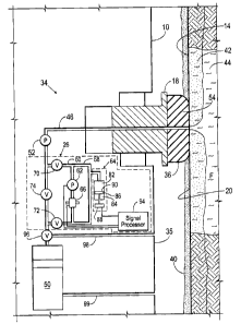
Figure 3 is a schematic representation of a portion of the down hole tool of
Figure 1
having a probe registered against a sidewall of the well bore and an
evaluation flow line of
the fluid analysis assembly communicating with an internal flow line
transporting formation
fluid from the probe.
Figure 4 is a schematic representation of a portion of yet another version of
the down
hole tool of Figure I having a probe registered against a sidewall of the well
bore and an
evaluation flow line of the fluid analysis assembly communicating with an
internal flow line
transporting formation fluid from the probe.
Figure 5A is a schematic representation of a portion of another version of the
down
hole tool of Figure I having a probe registered against a sidewall of the well
bore and an
evaluation flow line of the fluid analysis assembly communicating with an
internal flow line
transporting formation fluid from the probe.
7
CA 02544866 2006-04-25
Figure 5B is a schematic representation of the down hole tool of Figure 5A
showing
the reciprocation of formation fluid within the evaluation flow line.
Figure 6 is a schematic representation of a portion of another version of the
down
hole tool of Figure 1 having a probe registered against a sidewall of the well
bore and an
evaluation flow line of the fluid analysis assembly communicating with an
internal flow line
transporting formation fluid from the probe.
Figure 7 is a schematic representation of a portion of another version of the
down
hole tool of Figure 1 having a dual-probe registered against a sidewall of the
well bore and an
evaluation flow line of the fluid analysis assembly communicating with an
internal flow line
transporting formation fluid from the probe.
Definitions
Certain terms are defined throughout this description as they are first used,
while
certain other terms used in this description are defined below:
"Annular" means of, relating to, or forming a ring, i.e., a line, band, or
arrangement in
the shape of a closed curve such as a circle or an ellipse.
"Contaminated fluid" means fluid that is generally unacceptable for
hydrocarbon fluid
sampling and/or evaluation because the fluid contains contaminates, such as
filtrate from the
mud utilized in drilling the borehole.
"Down hole tool" means tools deployed into the well bore by means such as a
drill
string, wire line, and coiled tubing for performing down hole operations
related to the
evaluation, production, and/or management of one or more subsurface formations
of interest.
"Operatively connected" means directly or indirectly connected for
transmitting or
conducting information, force, energy, or matter (including fluids).
"Virgin fluid" means subsurface fluid that is sufficiently pure, pristine,
connate,
uncontaminated or otherwise considered in the fluid sampling and analysis
field to be
8
CA 02544866 2006-04-25
acceptably representative of a given formation for valid hydrocarbon sampling
and/or
evaluation.
"Fluid" means either "virgin fluid" or "contaminated fluid."
"Continuous" means marked by uninterrupted extension of time, space or
sequence.
Detailed Description
Presently preferred embodiments of the invention are shown in the above-
identified
figures and described in detail below. In describing the preferred
embodiments, like or
identical reference numerals are used to identify common or similar elements.
The figures
are not necessarily to scale and certain features and certain views of the
figures may be
shown exaggerated in scale or in schematic in the interest of clarity and
conciseness.
Figure 1 depicts a down hole tool 10 constructed in accordance with the
present
invention suspended from a rig 12 into a well bore 14. The down hole tool 10
can be any
type of tool capable of performing formation evaluation, such as drilling,
coiled tubing or
other down hole tool. The down hole tool 10 of Figure 1 is a conventional wire
line tool
deployed from the rig 12 into the well bore 14 via a wire line cable 16 and
positioned
adjacent to a formation F. An example of a wire line tool that may be used is
described in
US Patent Nos. 4,860,581 and 4,936,139.
The down hole tool 10 is provided with a probe 18 adapted to seal with a
wa1120 of
the well bore 14 (hereinafter referred to as a "wall 20" or "well bore wall
20") and draw fluid
from the formation F into the down hole tool 10 as depicted by the arrows.
Backup pistons
22 and 24 assist in pushing the probe 18 of the down hole tool 10 against the
well bore wall
20. The down hole tool 10 is also provided with a fluid analysis assembly 26
constructed in
accordance with the present invention for analyzing the formation fluid. In
particular, the
fluid analysis assembly 26 is capable of performing formation evaluation
and/or analysis of
9
CA 02544866 2006-04-25
down hole fluids, such as the formation fluids generated from formation F. The
fluid analysis
assembly 26 receives the formation fluid from the probe 18 via an evaluation
flow line 46.
Figure 2 depicts another example of a down hole tool 30 constructed in
accordance
with the present invention. The down hole tool 30 of Figure 2 is a drilling
tool, which can be
conveyed among one or more (or itself may be) a measurement-while-drilling
(MWD)
drilling tool, a logging-while-drilling (LWD) drilling tool, or other drilling
tool that are
known to those skilled in the art. The down hole too130 is attached to a drill
string 32 driven
by the rig 12 to fonm the well bore 14. The down hole tool 30 includes a probe
18a adapted
to seal with the wal120 of the well bore 14 to draw fluid from the formation F
into the down
hole tool 30 as depicted by the arrows. The down hole tool 30 is also provided
with the fluid
analysis assembly 26 for analyzing the formation fluid drawn into the down
hole tool 30.
The fluid analysis assembly 26 receives the formation fluid from the probe 18a
via flowline
46.
While Figures 1 and 2 depict the fluid analysis assembly 26 in a downhole
tool, it will
be appreciated that such an assembly may be provided at the wellsite, or an
offsite facility for
performing fluid tests. By positioning the fluid analysis assembly 26 in the
downhole tool,
real time data may be collected concerning downhole fluids. However, it may
also be
desirable and/or necessary to test fluids at the surface and offsite
locations. In such cases, the
fluid analysis assembly may be positioned in a housing transportable to a
desired location.
Alternatively, fluid samples may be taken to a surface or offsite location and
tested in a fluid
analysis assembly at such a location. Data and test results from various
locations may be
analyzed and compared.
Figure 3 is a schematic view of a portion of the down hole tool 10 of Figure 1
depicting a fluid flow system 34. The probe 18 is preferably extended from a
housing 35 of
the down hole tool 10 for engagement with the well bore wall 20. The probe 18
is provided
CA 02544866 2006-04-25
with a packer 36 for sealing with the well bore wall 20. The packer 36
contacts the well bore
wa1120 and forms a seal with a mud cake 401ining the well bore 14. The mud
cake 40 seeps
into the well bore wall 20 and creates an invaded zone 42 about the well bore
14. The
invaded zone 42 contains mud and other well bore fluids that contaminate the
surrounding
formations, including the formation F and a portion of the virgin fluid 44
contained therein.
The fluid flow system 34 includes the evaluation flow line 46 extending from
an inlet
in the probe 18. While a probe is depicted for drawing fluid into the down
hole tool, other
fluid communication devices may be used. Examples of fluid communication
devices, such
as probes and dual packers, used for drawing fluid into a flow line are
depicted in US Patent
Nos. 4,860,581 and 4,936,139.
The evaluation flow line 46 extends into the down hole tool 10 and is used to
pass
fluid, such as virgin fluid 44 into the down hole tool 10 for pre-test,
analysis and/or sampling.
The evaluation flow line 46 extends to a sample chamber 50 for collecting
samples of the
virgin fluid 44. The fluid flow system 34 may also include a pump 52 used to
draw fluid
through the flow line 46.
While Fig. 3 shows a sample configuration of a down hole tool used to draw
fluid
from a formation, it will be appreciated by one of skill in the art that a
variety of
configurations of flow lines, pumps, sample chambers, valves and other devices
may be used
and is not intended to limit the scope of the invention.
As discussed above, the down hole tool 10 is provided with the fluid analysis
assembly 26 for analyzing the formation fluid. In particular, the fluid
analysis assembly 26 is
capable of effecting down hole measurements, such as phase measurements,
viscosity
measurements and/or density measurements of the formation fluid. In general,
the fluid
analysis assembly 26 is provided with a chamber 60, a fluid movement device
62, a
11
CA 02544866 2006-04-25
pressurization assembly 64, and one or more sensors 66 (multiple sensors are
shown in
Figures 4, 5A, 5B, 6 and 7 and numbered by the reference numerals 66a-g for
purposes of
clarity).
The chamber 60 defines an evaluation cavity 68 for receiving the formation
fluid. It
should be understood that the chamber 60 can have any configuration capable of
receiving
the formation fluid and permitting movement of the fluid as discussed herein
so that the
measurements can be effected. For example, as shown in Figure 3, the chamber
60 can be
implemented as a bypass flow line communicating with the evaluation flow line
46 such that
the formation fluids can be positioned or diverted into the bypass flow line.
The fluid
analysis assembly 26 can also be provided with a first valve 70, a second
valve 72, and a
third valve 74 for selectively diverting the formation fluid into and out of
the chamber 60, as
well as isolating the chamber 60 from the evaluation flow line 46.
As shown, to divert the formation fluid into the chamber 60, the first valve
70, and the
second valve 72 are opened, while the third valve 74 is closed. This diverts
the formation
fluid into the chamber 60 while the pump 52 is moving the formation fluid.
Then, the first
valve 70 and the second valve 72 are closed to isolate or trap the formation
fluid within the
chamber 60. If desired, the third valve 74 can be opened to permit normal or a
different
operation of the down hole tool 10. For example, valve 74 may be opened, and
valves 70 and
72 closed while the fluid in chamber 60 is being evaluated. Additional valves
and flow lines
or chambers may be added as desired to facilitate the flow of fluid.
The fluid movement device 62 serves to move and/or mix the fluid within the
evaluation cavity 68 to enhance the homogeneity, cavitation, and circulation
of the fluid.
Fluid is preferably moved through evaluation cavity 68 to enhance the accuracy
of the
measurements obtained by the sensor(s) 66. In general, the fluid movement
device 62 has a
12
CA 02544866 2006-04-25
force medium applying force to the formation fluid to cause the formation
fluid to be
recirculated within the evaluation cavity 68.
The fluid movement device 62 can be any type of device capable of applying
force to
the formation fluid to cause the formation fluid to be recirculated and
optionally mixed
within the evaluation cavity 68. The fluid movement device 62 recirculates the
formation
fluid within the chamber 60 past the sensor(s) 66. The fluid movement device
62 can be any
type of pump or device capable of recirculating the formation fluid within the
chamber 60.
For example, the fluid movement device 62 can be a positive displacement pump,
such as a
gear pump, a rotary lobe pump, a screw pump, a vane pump, a peristaltic pump,
or a piston
and progressive cavity pump.
When the fluid movement device 62 mixes the fluid, one of the sensors 66
(typically
characterized as an optical absorption sensor) can be positioned immediately
adjacent to a
discharge side of the fluid movement device 62 to be within a vortex formed by
the fluid
movement device 62. The sensor 66 may be any type of sensor capable of
measuring fluid
parameters, such as a sensor or device effecting an optical absorbance
measurement.
Preferably, the pressurization assembly 64 changes the pressure of the
formation fluid
within the chamber 60 in a continuous manner. The pressurization assembly 64
can be any
type of assembly or device capable of communicating with the chamber 60 and
continuously
changing (and/or step-wise changing) the volume or pressure of the formation
fluid within
the chamber 60. In the example depicted in Figure 3, the pressurization
assembly 64 is
provided with a decompression chamber 82, a housing 84, a piston 86, and a
piston motion
control device 88. The piston 86 is provided with an outer face 90, which
cooperates with
the housing 84 to define the decompression chamber 82. The piston motion
control device
88 controls the location of the piston 86 within the housing 84 to effectively
change the
volume of the decompression chamber 82.
13
CA 02544866 2006-04-25
As the volume of the decompression chamber 82 changes, the volume or pressure
within the chamber 60 also changes. Thus, as the decompression chamber 82
becomes
larger, the pressure within the chamber 60 is reduced. Likewise, when the
decompression
chamber 82 becomes smaller, the pressure within the chamber 60 is increased.
The piston
motion control device 88 can be any type of electronic and/or mechanical
device capable of
effecting changes in the position of the piston 86. For example, the piston
motion control
device 88 can be a pump exerting on a fluid on the piston 86, or a motor
operably connected
to the piston 86 via a mechanical linkage, such as a post, flange, or threaded
screw.
The sensor 66 can be any type of device capable of sensing information which
is
helpful in determining a fluid characteristic, such as the phase behavior of
the formation
fluid. Although only one sensor 66 is shown in Figure 3, the fluid analysis
assembly 26 can
be provided with more than one sensor 66 as shown in Figures 6 and 7, for
example. The
sensors 66 can be, for example, a pressure sensor, a temperature sensor, a
density sensor, a
viscosity sensor, a camera, a visual cell, a NIR or the like. Preferably, at
least one of the
sensors 66 is used for an optical absorbance measurement. In this instance,
the sensor 66 can
be positioned adjacent to a window (not shown) so that the sensor 66 can view
or make
determinations with respect to the change in phase of the formation fluid. For
example, the
sensor 66 can be a video camera which would either permit viewing of the
formation fluid by
an individual, or take pictures of the formation fluid as it passes by the
window so that such
pictures could be analyzed for the presence of bubbles or other indications of
a change in
state of the phase of the formation.
The fluid analysis assembly 26 is also provided with a signal processor 94
communicating with the fluid movement device 62, the sensor(s) 66, and the
piston motion
control device 88. The signal processor 94 preferably controls the piston
motion control
device 88, and the fluid movement device 62 for effecting movement of the
formation fluid
14
CA 02544866 2006-04-25
within the chamber 60. The processor may also continuously change the pressure
of the
formation fluid in a predetermined manner. Although the signal processor 94 is
described
herein as only changing the pressure within the chamber 60 by the continuous
manner, it
should be understood that the signal processor 94 is adapted to modify the
pressure within the
chamber 60 in any predetermined manner. For example, the signal processor 94
can control
the piston motion control device 88 in the continuous manner, a stepped
manner, or
combinations thereof. The signal processor 94 also serves to collect and/or
manipulate data
produced by the sensor(s) 66.
The signal processor 94 can communicate with the fluid movement device 62, the
sensor(s) 66, and/or the piston motion control device 88 via any suitable
communication link,
such as a cable or wire communication link, an airway communication link,
infrared
communication link, microwave communication link, or the like. Although the
signal
processor 94 is illustrated as being within the housing 35 of the down hole
tool 10, it should
be understood by that the signal processor 94 can be provided remotely with
respect to the
down hole tool 10. For example, the signal processor 94 can be provided at a
monitoring
station located at the well site, or located remotely from the well site. The
signal processor
94 includes one or more electronic or optical device(s) capable of executing
the logic to
effect the control of the fluid movement device 62, and the piston motion
control device 88,
as well as to collect the information from the sensor(s) 66 described herein.
The signal
processor 94 can also communicate with and control the first valve 70, the
second valve 72,
and the third valve 74 to selectively divert fluid into and out of the
evaluation cavity 68 as
discussed above. For purposes of clarity, lines showing the communication
between the
signal processor 94 and the first valve 70, second valve 72 and the third
valve 74 have been
omitted from Figure 3.
CA 02544866 2006-04-25
In use, the signal processor 94 may be used to selectively actuate valves 70,
72,
and/or 74 to divert the formation fluid into the chamber 60, as discussed
above. The signal
processor 94 may close the valves 70 and 72 to isolate or trap the formation
fluid within the
chamber 60. The signal processor 94 may then actuate the fluid movement device
62 to
move the formation fluid within the chamber 60 in a re-circulating manner. As
shown in
Figure 3, this recirculation forms a loop that passes pressurization assembly
64, sensor 66 and
fluid movement device 62. This loop is formed from a series of flowlines that
are joined in
fluid communication to form a flow loop. In small spaces, such as in the
downhole tool, fluid
typically travels through narrow flowlines. Mixing in such narrow flowlines is
often
difficult. The fluid is, therefore, circulated in a loop to enhance mixing of
the fluid as it
passes through narrow flowlines. Such loop mixing may also be desirable in
other
applications that do not involve narrow flowlines.
The signal processor 94 actuates the piston motion control device 88 to begin
changing the pressure within the chamber 60 in a predetermined manner. In one
example,
the signal processor 94 actuates the piston motion control device 88 to
continuously
depressurize the formation fluid within the chamber 60 at a rate suitable to
effect phase
measurements in a short time, sometimes less than 15 minutes. While the
chamber 60 is
being continuously depressurized, the signal processor 94 collects data from
the sensor(s) 66
to preferably effect an optical absorbance measurement (i.e. scattering) while
also monitoring
the pressure within the chamber 60 to provide an accurate measurement of the
phase behavior
of the formation fluid.
The down hole tool 10 is also provided with a fourth valve 96 for selectively
diverting
the formation fluid into the sample chamber 50, or to the well bore 14 via a
return line 98.
The down hole tool 10 may also be provided with an exit port 99 extending from
a back side
of sample chamber 50.
16
CA 02544866 2006-04-25
It should be understood that the fluid analysis assembly 26 can be utilized in
various
manners within the down hole tools 10 and 30. The description above regarding
the
incorporation of the fluid analysis assembly 26 within the down hole tool 10
is equally
applicable to the down hole too130. Further, various modifications to the down
hole tools 10
and 30 with respect to the fluid analysis assembly 26 is contemplated by way
of the present
invention. A variety of these modifications will be described below with
respect to the down
hole tool 10. However, it should be understood that these modifications are
equally
applicable to the down hole tool 30.
It should be understood that phase behavior measurements are not the only
measurements that can be made and while it is plausible that phase border
determinations are
more sensitive to agitation it is also desirable for precise measurements of,
for example,
density in a multi-component mixture and also for viscosity. Indeed,
measurements can be
done with either continuous or step-wise depressurization. If step wise then
an additional
mode of operation becomes possible by performing the depressurization to the
phase border
twice either with the same sample or preferably with a fresh aliquot of fluid
from the flow-
line. If this is adopted with discrete pressure steps then the first
depressurization with
constant depressurization leads to a rough estimate of the phase border
pressure. The rough
estimate can be used in a second depressurization cycle with logarithmically
decreasing step
sizes used with decreasing pressure: e.g., the magnitude of the pressure
decrement decreases
logarithmically (or in some other mathematical manner so that the pressure
decrements
decrease) with decreasing pressure as the pressure tends to the estimate
obtained from the
first measurement. At pressures below that estimate, the pressure step size
increases with
decreasing pressure. This procedure can give a more precise answer.
The temperature and to a far lesser extent the pressure in the down hole tool
10 or 30
may not be equal to those of the reservoir F. To obtain estimates at the
required state from
17
CA 02544866 2006-04-25
the values measured at the state of the down hole tool 10 or 30 desirably
includes both an
estimate of the reservoir temperature and pressure and the variation of the
properties with
temperature and pressure and these values combined with a model that can
extrapolate from
one set of temperatures and pressures to another. Thus, measurements are
desirably
performed at that zone and while changing to another zone or retracting the
down hole tool
or 30 so that the required derivatives can be measured and then combined with
an
equation of state.
Figures 4-7 will now be discussed. To simplify Figures 4-7, the signal
processor 94
and associated communication links are not shown.
Shown in Fig. 4 is a down hole tool l0a which is similar in construction and
function
to the down hole tool 10 described above with reference to Fig. 3, with the
exception that the
down hole tool l0a is provided with two fluid analysis assemblies 26. The
advantage of
having multiple fluid analysis assemblies 26 permits the down hole tool l0a to
retrieve more
than one sample of the formation fluid and to test the samples either
simultaneously or
intermittently. This permits comparisons of the results of the samples to
provide a better
indication of the accuracy of the down hole measurements. Although only two of
the fluid
analysis assemblies 26 are shown in Figure 4, it should be understood that the
down hole tool
l0a could be provided with any number of the fluid analysis assemblies 26 at
various
locations in the downhole tool. In the example shown in Figure 4, each of the
fluid analysis
assemblies 26 selectively communicate with the evaluation flow line 46. It
should also be
understood that the fluid analysis assemblies 26 can be operated independently
and/or used
on independent flowlines.
Shown in Figures 5A and 5B is a down hole tool l Ob which is similar in
construction
and function to the down hole tool 10 described above with reference to Fig.
3, with the
exception that the down hole tool l Ob includes a pump assembly 180 which
combines the
18
CA 02544866 2006-04-25
functionality of the fluid movement device 62 and the pressurization assembly
64 of Fig. 3.
Figure 5A shows the downhole tool l Ob with the pump assembly in the upstroke
position,
and figure 5B shows the downhole tool l Ob with the pump assembly in the
downstroke
position. The pump assembly 180 is provided with a first vessel 182, a second
vessel 184, a
piston assembly 186, and a source of motive force 188.
The piston assembly 186 includes a first body 192 slidably positionable within
the
first vessel 182 to define a first chamber 193 communicating with the
evaluation cavity 68.
The piston assembly 186 also includes a second body 194 slidably positionable
within the
second vessel 184 to define a second chamber 196 communicating with the
evaluation cavity
68. Figures 5a and 5b illustrate the movement of the first and second bodies
192 and 194.
The source of motive force 188 moves the first and second bodies 192 and 194
of the
piston assembly 186 such that the formation fluid trapped within the chamber
60 is diverted
past the sensors 66a-e and between the first and second chambers 193 and 196
as the relative
positions of the first and second bodies 192 and 194 are changed. To cause a
change in
pressure as the first and second bodies 192 and 194 are moved, the first
chamber 193 is
provided with a diameter A, and the second chamber 196 is provided with a
diameter B. The
diameter B is preferably smaller than the diameter A. Because the first and
second chambers
193 and 196 have different diameters, the combined volume of the first chamber
193, the
second chamber 196, and the evaluation cavity 68 changes as the first and
second bodies 192
and 194 move.
The source of motive force 188 simultaneously moves the first and second
bodies 192
and 194 in a first direction 200 as shown in Figure 5B to cause the formation
fluid F to move
from the second chamber 196 to the first chamber 193 past the sensors 66a-e
while
depressurizing the evaluation cavity 68. For example, if during a motion of
distance (ds), the
first body 192 in the first chamber 193 sucks in about 5cc of fluid and the
second body 194 in
19
CA 02544866 2006-04-25
the second chamber 196 pushes out about 4.8cc of fluid, there will be a net
increase of about
0.2cc while about 4.8cc of formation fluid F moves past the sensors 66a-e.
The source of motive force 188 can be any device or devices capable of moving
the
first body 192 and the second body 194. For example, the piston assembly 186
can include a
drive screw 202 connected to the first body 192 and the second body 194. The
source of
motive force 188 can drive the drive screw 202 with a motor 204 operably
connected to a
drive nut 206 positioned on the drive screw 202. Alternatively, a hydraulic
pump can reset or
control the position of the piston assembly 186.
Shown in Figure 6 is a down hole tool l Oc which is similar in construction
and
function to the down hole tool l0a described above with reference to Figure 4,
with the
exception that the down hole tool l Oc is further provided with one or more
isolation valves
220 and 222. The down hole tool l Oc is provided with two or more fluid
analysis assemblies
26. As discussed above with reference to Figure 4, the advantage of having
multiple fluid
analysis assemblies 26 permits the down hole tool l0a or l Oc to retrieve more
than one
sample of the formation fluid and to test the samples either simultaneously or
intermittently.
This permits comparisons of the results of the samples to provide a better
indication of the
accuracy of the down hole measurements.
With the addition of the isolation valves 220 and 222 connecting the chamber
60 of
one of the fluid analysis assemblies 26 to the chamber 60 of another one of
the fluid analysis
assemblies 26, the down hole tool l Oc permits the isolation valves 220 and
222 to be opened
so as to mix the samples separately trapped by the two fluid analysis
assemblies 26. The
isolation valves 220 and 222 can then be closed and the mixed formation fluids
separately
tested by the fluid analysis assemblies 26.
CA 02544866 2006-04-25
Shown in Figure 7 is a down hole tool I Od which is similar in construction
and
function to the down hole tool 10a described above with reference to Figure 4,
with the
exception that the down hole tool 10d is further provided with a probe 230
having a cleanup
flow line 232 in addition to the evaluation flow line 46, and one of the fluid
analysis
assemblies 26 is connected to the cleanup flow line 232. The down hole tool
10d is also
provided with a pump 234 connected to the cleanup flow line 232 for drawing
contaminated
fluid out of the formation and for diverting the contaminated fluid to the
fluid analysis
assembly 26.
The fluid analysis assemblies 26 may be used to analyze the fluid in the
evaluation
and cleanup flow lines 46 and 232. The information generated from the fluid
analysis
assemblies 26 may be used to determine such information as contamination
levels. As
shown, the evaluation flow line 46 is connected to the sample chamber 50 so
that fluids may
be sampled. Such sampling typically occurs when contamination levels fall
below an
accepted level. The cleanup flow line 232 is depicted as connected to the well
bore 14 to
dump fluid out of the tool 10d. Optionally, various valving can be provided
for selectively
diverting fluid from one of more flow lines into sample chambers or the well
bore as desired.
While the down hole tools depicted herein are shown as having probes for
drawing
fluid into the down hole tool. It will be appreciated by one of skill in the
art that other
devices for drawing fluid into the down hole tool may be used. For example,
dual packers
may be radially expanded about the intake of one or more flow lines to isolate
a portion of
the well bore 14 there between, and draw fluid into the down hole tool.
Further, while the fluid analysis assembly 26 has been shown and described
herein
used in combination with the down hole tools 10, IOa, l Ob, l Oc, l Od and 30,
it should be
understood that the fluid analysis assembly 26 can be utilized in other
environments, such as
a portable lab environment, or a stationary lab environment.
21
CA 02544866 2006-04-25
It will be understood from the foregoing description that various
modifications and
changes may be made in the preferred and alternative embodiments of the
present invention
without departing from its true spirit.
This description is intended for purposes of illustration only and should not
be
construed in a limiting sense. The scope of this invention should be
determined only by the
language of the claims that follow. The term "comprising" within the claims is
intended to
mean "including at least" such that the recited listing of elements in a claim
are an open
group. "A," "an" and other singular terms are intended to include the plural
forms thereof
unless specifically excluded.
22