Note: Descriptions are shown in the official language in which they were submitted.
CA 02545026 2006-04-27
PAPER HANDLING SYSTEM FEEDER ADJUSTMENT FOR STACK ELEVATOR
MECHANISMS
FIELD OF THE INVENTION
[001] The present invention relates to paper handling systems, such as
folders,
inserters, printers and copier systems, and more particularly, to a feeder
adjustment
for a paper stack elevator mechanism.
BACKGROUND OF THE INVENTION
[002] Various products require media feeders for different types of media to
be
processed by a paper handling system. Media feeders for envelopes, sheets,
inserts
and the like are used in various equipment, such as folders, inserters,
printers and
copiers. A common problem in feeders for equipment of this type is a high
fault rate
in feeding media. This is because the adjustment of the media side guides is
often
highly dependent on operator skill in making the required adjustment. If the
operator
sets the side guides too tight, mis-feeds frequently occur. The setting of
side guides
too tight against the stack of media can also cause the erratic performance in
the
stack elevator mechanisms used for moving the media to be in engagement with
the
singulator and feeder mechanisms.
[003] If the operator sets the side guides too loose, then the envelopes can
skew
and become offset while they are being fed. This can create errors in printing
registration and folding operations, as well as jams in the equipment and
other
related problems. For some feeders, when the side guides are set too loose,
the
rate of multi-feeding may increase. Incorrectly setting side guides results in
higher
rates of many types of machine faults and shutdowns. Operators often gain
experience in setting the side guides by trial and error; however, having
experienced
operators are often more highly paid, which can increase the cost of operating
the
equipment, particularly high speed equipment where there may be frequent need
for
replenishing the media, as for example, on high speed copiers, laser printers,
addressing machines and other types of imaging and office equipment. In
situations
where experienced operators move on to other jobs and are replaced by
1
CA 02545026 2006-04-27
inexperienced operators, the inexperienced operator must acquire the knowledge
and skill required for optimal adjustments to feeder side guides. Often this
process
is again accomplished by trial and error, resulting in unsatisfactory
performance of
the feeder until the operator obtains the requisite skill in adjusting the
side guides.
These problems occur in both center registered and also in edge registered
type
media feeders. For typical media processing systems, when the media is center
registered, both side guides are adjusted. When the media is edge registered,
typically only one side guide is adjusted.
[004] Various techniques have been provided to help assist operators in
setting
the adjustment. For example, with well-controlled known standard sizes, such
as 8-
1/2" x 11" (letter), 8-1/2" x 14" (legal), A4 size sheets, as well as other
size sheets,
detents have been provided in assisting in setting the side guides. While the
tolerances of standard cut sheet letter size media is typically quite reliable
with a
tolerance of +/- 0.5mm. However, the size tolerances for envelopes, inserts
and
pre-printed sheet media are often not as accurate and can be unpredictable,
frequently having variations of +/- 2-3 mm. Accordingly, the provision of
detent-type
solutions in positioning the side guides for media of this type will not be
satisfactory
because of the high tolerances in the media dimensions. For example, if a
detent is
designed to locate the side guide for an average envelope size, and envelope
having
a tolerance on the large side of nominal could be compressed by 3 mm, which
will
significantly increase the rate of mis-feeds. Alternatively, if the detent is
located at
the maximum tolerance to accommodate the envelopes with the largest positive
tolerance, when envelopes with the largest negative tolerance are loaded, it
will
result in a gap of 6 mm between the stack of envelopes and the side guide.
This
large gap wili result in a significantly higher number of skewed feeds, which
can
increase the number of jams and other types of faults downstream in the
process.
Besides jams, some typical faults associated with skewed feeds include
misaligned
images on the media in the case of a printing system, or increased insertion
faults in
the case of an insertion system. In cases such as this, at times various
operator aids
to set the side guides are employed such that the gap between the side guides
and
the edge of the material is appropriately adjusted. In some systems, in order
to
compensate for the lack of operator skills in adjusting feeder side guides,
expensive
2
CA 02545026 2006-04-27
mechanisms are added to de-skew the envelope, and sometimes to re-center the
envelope before moving it down stream for printing or insertion.
[005] In high capacity feeders that typically employ an elevator mechanism,
the
problem is compounded. The operator often may load the feeder tray in several
steps. The operator frequently loads several handfuls or reams of media in
discrete
steps. In such a situation, each handful loaded may not be perfectly aligned
with the
previously loaded handful. Batches of the media in the stack can thus be
slightly
offset from other batches loaded into the feeder. Also, the entire stack can
be
slightly skewed between the side guides. If the operator moves the side guides
tightly against the edges of the media after the stack of media has been
loaded into
the feeder in order to push all individual batches toward the center until the
edges
are aligned, this may correct the situation. But, often, as a result, this
operator action
to correct the misalignment of the stack often leads the side guides being set
too
snug against the edges of the stack. This can cause mis-feed failures or
elevator
mechanism failures. A similar type of problem also occurs in low capacity
feeders in
which a single handful or ream of media may be loaded in the feeder if the
media is
not placed perfectly centered between the side guides. In such case the
operator
may use the adjustment of the side guides to center the stack, which results
in a
similar type of problem noted above in connection with high capacity media
feeders,
where the guides are too snug against the edge of the stack.
[006] The problem of adjusting the media guides has been noted in U.S. Patent
Number 6,793,215B2 for "Self-Adjusting Side Guide in Mail Handling Device."
The
patent discloses a self-adjusting guide, which is provided for a document-
handling
machine having a feed deck along which documents are transported. The self-
adjusting side guide includes a member mounted for movement along the feed
deck
toward and away from the documents. A side guide self-adjusts to correct the
drag
effect problem.
SUMMARY OF THE INVENTION
[007] The present invention provides an arrangement for setting the side
guides in
the correct position for media feeders, which results in significant
improvement in the
3
CA 02545026 2006-04-27
performance of the system and enables untrained operators to be as proficient
as
trained operators in setting the side guides. The present invention provides
improvements for both center registered and edge registered type media
feeders.
[008] The present invention is particularly useful in feeders where the
material is
loaded onto a feeder platform, where the material may be mis-aligned with
respect to
the side guides and in high capacity feeder arrangements where the material is
be
loaded into the feeder in batches to completely fill the feeder.
[009] The present invention provides enhanced operation of the feeders for
paper
handling systems where an operator opens a feeder closure and loads a stack of
media between the side guides. The operator adjusts a mechanism until the side
guides are snug against the media stack. The adjustment includes a clutch
arrangement, which will slip if the operator sets the guides too snugly
against the
media stack. The operator then closes the feeder closure and the mechanism
associated with the closure acts to back the side guides away from the stack
of
media a required amount for appropriate operation of the feeder and
appropriate
operation of the elevator mechanism. In accordance with the invention, the
force
exerted by the operator in making the adjustment is sufficient to align mis-
aligned
media such that the back-off of the side guides is sufficient to allow proper
feeding.
The clutch limits the force with which the side guides can be moved against
the
media stack.
[0010] A media feeder embodying the present invention for feeding media items
includes a moveable media side guide. A force limiting mechanism coupled is to
move the side guide such that the side guide can be moved into engagement with
media items with a force that will not exceed a predetermined level. A second
mechanism is coupled to move the side guide a predetermined distance away from
the media items.
[0011] In another embodiment of the present invention, a media feeder for
feeding
media items from a stack of media items includes a media feed means for
separating
and feeding a single media item from a stack of media items. A first and a
second
moveable media side guides are mounted adjacent a media elevator platform. The
4
CA 02545026 2006-04-27
media elevator platform is moveable toward and away from the media feed means.
A media side guide adjustment mechanism is connected to the first and the
second
side guides such that when the adjustment mechanism is moved in a first
direction
the first and second side guides will move toward each other and when the
adjustment mechanism is moved in a second direction the first and said second
side
guide will move away from each other. A first drive means is connected to the
side
guide adjustment mechanism and is operable to cause the side guide adjustment
mechanism to move in the first and the second direction. A second drive means
is
connected to the side guide adjustment mechanism and is operable to cause the
side guide adjustment mechanism to move a predetermined amount in the second
direction such that a predefined gap is established between media items on the
platform and the a first and a second moveable media side guides after the
side
guides are moved into engagement with the media items.
[0012] In still another embodiment of the present invention a media feeder for
feeding media items includes a media feed mechanism. A media elevator platform
is
mounted for supporting media items and is within a housing. The housing
includes a
hinged cover. The media elevator platform moveable in a vertical direction
toward
and away from the media feed mechanism. A first and a second media side guide
are mounted adjacent the media elevator platform and are moveable in a
horizontal
direction. An adjustment mechanism, such as a lead screw, is connected to the
first
and the second side guides such that when the adjustment mechanism is moved in
a
first direction the first and second side guides will move toward each other
and when
the adjustment mechanism is moved in a second direction the first and said
second
side guide will move away from each other. A first drive mechanism is
connected to
the adjustment mechanism and operable to cause the adjustment mechanism to
move in the first and the second direction. A second drive means is connected
to
the housing cover and to the adjustment mechanism and is operable to cause the
adjustment mechanism to move in said the direction when the cover is opened
and
in the second direction when the cover is closed.
[0013] A method for adjusting media side guides embodying the present
invention
includes the steps of opening a media feeder housing cover and loading a stack
of
media items onto a feeder elevator platform within the housing. Moving media
side
CA 02545026 2008-09-04
guides are through a force limiting drive arrangement into engagement with the
sides
of the stack of media items, the force being sufficient to align misalinged
media items
on the feeder elevator platform. Causing the media side guide drive to be
operated
by closing the housing cover such that the side guides move away from the
stack of
media items to establish a gap between the stack of media items and the side
guides.
[0013A] In accordance with one aspect of the present invention, there is
provided a media feeder for feeding media items from a stack of media items,
comprising:
a media feed means for separating and feeding single media items from a
stack of media items;
a media elevator platform moveable toward and away from said media feed
means;
first and second moveable media side guides mounted adjacent said media
elevator platform;
a side guide adjustment mechanism connected to said first and said second
side guides such that when said side guide adjustment mechanism is moved in a
first direction said first and second side guides will move toward each other
and
when said side guide adjustment mechanism is moved in a second direction said
first and said second side guides will move away from each other, wherein the
side
guide adjustment mechanism includes a lead screw having a first portion with
right
hand threads operatively connected with said first side guide and a second
portion
with left hand threads operatively connected with said second side guide;
a first drive means connected to said side guide adjustment mechanism
operable to cause said side guide adjustment mechanism to move in said first
and
said second directions; and
a second drive means connected to said side guide adjustment mechanism
operable to cause said side guide adjustment mechanism to move a predetermined
amount in said second direction such that a predefined gap is established
between
media on said platform and said first and said second moveable media side
guides
after said side guides are moved into engagement with said media.
6
CA 02545026 2008-09-04
[0013B] In accordance with another aspect of the present invention, there is
provided a media feeder for feeding media items, comprising:
a media feed mechanism;
a housing having a cover hinged thereto;
a media elevator platform mounted within said housing for supporting media
items, said media elevator platform moveable in a vertical direction toward
and away
from said media feed mechanism;
first and second media side guides mounted adjacent said media elevator
platform, said side guides moveable in a horizontal direction;
a side guide adjustment mechanism connected to said first and said second
side guides such that when said side guide adjustment mechanism is moved in a
first direction said first and second side guides will move toward each other
and
when said side guide adjustment mechanism is moved in a second direction said
first and said second side guides will move away from each other;
a first drive mechanism, said first drive mechanism connected to said side
guide adjustment mechanism and operable to cause said side guide adjustment
mechanism to move in said first and said second direction; and
a second drive means connected to said housing cover and to said side guide
adjustment mechanism and operable to cause said side guide adjustment
mechanism to move in said first direction when said cover is opened and said
second direction when said cover is closed.
BRIEF DESCRIPTION OF THE DRAWINGS
[0014] Reference is now made to the figures wherein like reference numerals
designate similar items in the various views and in which:
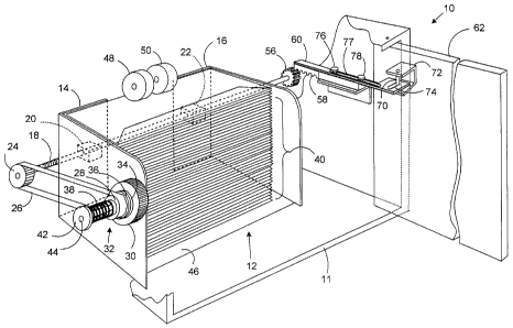
[0015] Fig. 1 is a perspective view of a paper handling system with a media
feeder
with a media stack elevator mechanisms and a moveable side guide adjustment
arrangement embodying the present invention;
6a
CA 02545026 2008-09-04
[0016] Fig. 2 is a perspective view of those parts of the feeder shown in Fig.
1,
helpful in an understanding of the present invention with an aligned stack of
envelopes on the feeder media support elevator platform and with the feeder
cover
in the fully open position;
[0017] Figs. 3- 5 are perspective views of those parts of the feeder shown in
Fig.
1, helpful in an understanding of the present invention and the sequence of
operation
to adjust the feeder moveable side guides, and showing the feeder cover in the
fully
closed position in Fig. 3, showing the feeder cover in the fully opened
position with a
misaligned stack of envelopes on the elevator support platform in Fig. 4, and
showing the feeder cover in the fully closed position in Fig 5; and,
[0018] Fig. 6 is a perspective view of the feeder shown in Figs. 1-5 showing
details
of the feeder elevator mechanism drives.
6b
CA 02545026 2006-04-27
DETAILED DESCRIPTION OF THE PREFERRED EMBODIMENT
[0019] Reference is now made to the various figures and more particularly to
Fig. 1.
A paper handling system 10 has a feeder housing 11 that encloses a media
feeder
12. Depending on the design, the housing 11 may partially or fully enclose the
media feeder 12. The media feeder 12 includes moveable media side guides 14
and
16. A lead screw 18 is threaded through a member 20 attached to side guide 14
and
a member 22 attached to side guide 16. The lead screw 18 has a left-hand
thread
associated with one of the side guides and the right-hand thread associated
with the
other of the side guides. Thus, when lead screw 18 is rotated, the side guides
14
and 16 will move toward each other or away from each other, depending upon the
direction the lead screw 18 is turned. The side guides can be connected by
other
arrangements, such as using gear segments, or opposing racks, which engage a
single pinion to cause both side guides to move toward or away from the center
of
the paper path. These and other arrangements can be incorporated into the
present
system.
[0020] It should be noted that the present system can also beneficially be
employed
where only one side guide is adjusted. For example with edge-registered
systems,
only one side guide is moved to accommodate different sizes of media. However,
the same type limitations apply regarding the setting of a gap between the
media
and the adjustable side guide. Accordingly, the present system is applicable
to such
arrangements where only one media guide is adjusted and similar performance
improvements will be obtained as for center-registered systems.
[0021] A pulley 24 is affixed to the lead screw 18 and a belt drive 26 is used
to
transmit torque from a second pulley 28 connected to an adjustment thumb wheel
30
by a slip clutch shown generally at 32 and including two clutch faces 34 and
36.
Clutch face 34 is affixed to adjustment thumb wheel 30 and clutch face 36 is
affixed
to pulley 28. A spring 38 provides a normal force between the two clutch faces
34
and 36. The arrangement provides a torque limiting mechanism. Other types of
torque or force limiting mechanisms can be employed to provide the needed
functionality.
7
CA 02545026 2008-09-04
[0022] The force of spring 38 and coefficient of friction of the clutch faces
34 and 36
act together to establish the magnitude of toque that can be transmitted
through the
clutch faces. Thus, when the operator turns the adjustment wheel 30, torque is
transmitted through clutch faces 34 and 36 to the pulley 28, which drives the
belt 26,
to turn the lead screw 18. This results in movement of the side guides. The
direction of movement depends upon the direction of rotation of the adjustment
thumb wheel 30 and thus the direction of rotation of the lead screw 18. When
the
side guides are moved toward the stack of media 40, shown as envelopes, and
eventually contact the edge of the stack of media 40, resistance will be
transmitted
back through the belt 26 to the adjustment wheel 30. When the resistance
becomes
sufficiently high, clutch faces 34 and 36 slip. Slip clutch 32 no longer
transmits
torque from the adjustment wheel 32 to the lead screw 18, and movement of the
side
guides 14 and 16 stops.
[0023] The value of the torque at which the clutch 32 slips may be pre-
established
for correcting a situation in which an operator loads media into the feeder
12, and the
edges of the media are not well aligned. One of the functions of the side
guides 14
and 16 adjustment is to press against the edge of the stack to align the media
if
needed. A certain amount of force is required to accomplish this alignment
depending on the specific parameters of a particular feeder design, such as
the
maximum stack capacity, the method of feeding, and the type of media to be
fed.
For a particular feeder design, test data will be used to establish the forces
required
to align the stack. Components of the clutch assembly, such as the materials
of the
clutch faces, spring force, and spring compression, will be selected as part
of the
design to accomplish the necessary adjustment force. It may be that the torque
on
the clutch 32 is adjusted at the factory to achieve this desired force by
tightening nut
42, which captures the spring 38 and may be tightened on shaft 44 to increase
the
force exerted by the spring on the clutch faces 34 and 36. This adjustment
will
accomplish the objective of providing both sufficient torque to align the
stack when
the side guides are adjusted toward the stack, and then slip if the operator
attempts
to apply more torque than is necessary to align the stack.
8
CA 02545026 2006-04-27
[0024] Other factors affect the feeder performance. The media 40 rests on a
media
support elevator platform 46 that must raise the stack of media 40 to the feed
rollers
48 and 50 or other suitable media feed mechanisms, such as feed belt
arrangement,
in order to initiate feeding. When the side guides 14 and 16 have been moved
to
align the edges of the stack 40, the result is a high drag force between the
side
guides 14 and 16 and the media stack 40 when the stack 40 is lifted by the
elevator
motor 49 (Fig. 6) operating to rotate a lift screw 51 to lift the elevator
platform 46 via
a lift nut 52 attached to the platform 46. If the drag forces created by the
adjustment
of side guides 14 and 16 create a drag that is too high, the elevator motor 49
will
stall. Additionally, drag of the stack of media against the side guides while
the
elevator is operating may cause the edges of the media near the top of the
stack to
be bent in a direction opposite the direction of elevator motion. This
distortion in the
edges of the media could result in a higher rate of mis-feeds and multi-feeds.
[0025] The problems of inappropriately adjusting the side guides 14 and 16 so
that
they are left in a position too snug against the edge of the stack of media
are
avoided in the present arrangement by automatically backing off the side
guides 14
and 16 away from the media stack 40 after the stack has been aligned. A pinion
gear 56 is attached to the lead screw 18. A rack gear 58 mounted on a sliding
arm
60 is operated in a linear movement to turn the pinion gear 56. The linear
motion of
the sliding arm 60 and rack gear 58 is provided by the motion of a cover 62,
which
encloses the media stack 40 and is moveably attached, such as being hinged to
the
feeder housing 11 as shown in Fig. 1. It should be noted that the cover 62
could be
a door or a different type moveable member, such as a lever, associated with
the
feeder. Depending on the design, the closeable cover may partially or fully
cover the
media 40 when it is placed in the feeder 12. When the cover 62 is opened, the
sliding arm 60 and the rack gear 58 are moved in a first direction. This
movement
turns the pinion gear 56 and lead screw shaft 18 a small amount. This rotation
causes the side guides 14 and 16 to move toward each other a small amount.
[0026] When the cover 62 is opened, the operator may load a stack of media and
adjust the position of the side guides 14 and 16 by turning the adjustment
thumb
wheel 30 until the value of the slip torque of the clutch 32 is achieved as
described
above and clutch faces 34 and 36 slip, so that the side guides are snug
against the
9
CA 02545026 2006-04-27
stack of media 40. When the cover 62 is closed, the sliding arm 60 and rack
gear 58
are moved in a second direction, which turns the pinion gear 56 and lead screw
18 in
a second direction, which moves the side guides 14 and 16 away from the media
stack 40 a small distance. One suitable distance may be, for example, about
0.5mm. After these steps are completed, the stack of media 40 has been well
aligned and the side guides 14 and 16 have been moved away from the stack of
media items 40 so that no drag will occur between the side of the stack and
side
guides 14 and 16. Thus, there will be no additional drag to be overcome by the
elevator motor 49 as it lifts media support elevator platform 46 and no
additional drag
on the top item of the media stack 40 when it engages feed rollers 48 and 50,
which
might contribute to mis-feeds. And media skew during the feeding operation
will be
limited. This results in a significant improvement in performance of the
feeder 12
and facilitates utilization of the equipment by operators without training or
experience
in the appropriate positioning of side guides for proper operation.
[0027] In operation as shown in Figs. 3, 4 and 5, as the cover 62 swings open
to
the position shown in phantom, the sliding arm 60 with the rack gear 58 is
pulled
outwardly by a pin 70 attached by U-shaped bracket 72 connected to cover 62.
During the opening and closing of the cover 62, the pin 70 rides in a slot 74
of the
sliding arm 60. The rack gear 58 on the sliding arm 60, in contact with the
pinion
gear 56, causes the lead screw 18 to rotate as the sliding arm 60 is guided in
a linear
movement by the slot 77 which is mounted to guides 76 and 78. The guides 76
and
78 are connected to a bracket 80 mounted to the feeder housing 11. A suitable
rotation for the pinion gear 56 may be in the range of 70-100 . This action on
the
lead screw 18 causes the side guides to move toward each other about 0.5 mm,
depending upon the dimensions, including the threads and gear ratios of the
various
parts.
[0028] As shown in Fig. 4, when the cover 62 is fully opened, the rack gear 58
mounted on the sliding arm 60 is fully disengaged from the pinion gear 56 on
the
right end of the lead screw 18. At this time, the operator loads the media 40,
shown
in Fig. 4 as mis-aligned, and then adjusts the position of the side guides 14
and 16
by turning the adjustment thumb wheel 30. In order to align the media stack
40, as
shown in Fig. 4, the thumb wheel 30 is operated until the slip torque
associated with
CA 02545026 2006-04-27
the clutch 32 is reached. This torque is sufficient to move the media stack 40
into
good alignment. If the operator continues to rotate the thumb wheel 30 and
tries to
add additional pressure or squeeze the stack of media 40 too tightly, the slip
clutch
32 will no longer transmit further rotary motion to the pulley 24 and thus
lead screw
18. The side guides 14 and 16 will stop moving regardless of how much the
operator rotates the adjustment thumb wheel 30.
[0029] As shown in Fig. 5, as the cover 62 swings closed from its open
position
shown in phantom, the sliding arm 60 moves the rack gear 58 back into
engagement
with the pinion gear 56. This causes the lead screw 18 to rotate. This action
on the
lead screw 18 causes the side guides 14 and 16 to move away from the stack of
media to establish a predetermined gap for feeding media items from the media
stack 40. When there is a sufficient gap between the gap of the edge of the
media
stack 40 and the side guides 14 and 16, for example 0.5mm, it reduces the drag
in
order to minimize the stack elevator drive torque required for elevator motor
49 to lift
the media support platform 46 and prevents mis-feeds, while simultaneously
limiting
the amount of skew on the media as they are fed from the stack of media 40.
The
predetermined distance from the edge of the stack 40 for each side guide 14
and 16
caused by closing the cover 62 will typically be small such as within the
range of 0.2
mm to 1.0 mm, in contrast to the movement of the side guides caused by the
operation of the adjustment thumb wheel 30 where the distance from the edge of
the
stack 40 for each side guide 14 and 16 to facilitate the loading on the media
stack 40
onto the media support elevator platform 46 will be whatever distance is
created by
the operator if the operator rotates the thumb wheel 30 in a direction to
increase the
distance between the side guides to facilitate loading the media. The
predetermined
distance is a matter of design choice based on the types of media items
involved and
the specific design of the feeder equipment.
[0030] The system described above can be automated. For example, both the
adjustment of the adjustment thumb wheel 30 and the rack and pinion motion
associated with the cover 62, could be accomplished by actuators such as
motors or
solenoids, which will do the adjustments automatically. The same two
requirements
to align the stack and eliminate the drag forces are met in the following
manner.
After the operator has loaded a stack of media and before the feed cycle is
initiated,
11
CA 02545026 2006-04-27
the motor drives the side guides through a drive mechanism, that may be
similar to
the type of mechanism previously described, until the side guides have moved
toward each other sufficiently to align the media stack. The drive mechanism
may
include a slip clutch similar to clutch 32 or have a maximum torque output of
the
drive motor, which would stall when the torque is reached. These approaches
limit
maximum drive force on the side guide(s) but provide a force, which is
sufficient to
align the media stack. However, the side guides cannot be pressed too tightly
against the stack thereafter. The motor then reverses a distance sufficient to
back
off the side guides away from the stack the same small distance above, for
example
about 0.5 mm.
[0031] A semi-automatic variation also applies. Either of the two steps could
be
automated with the other step remaining manual operation performed by the
operator. For example, the adjustment wheel 30 with slip clutch 32 could be
used to
move the side guides against the stack and provide stack alignment but moving
the
guides away from the stack could be provided by an automated mechanism. The
motor function described above could be used only for this second step.
Alternatively, a solenoid-operated ratcheting mechanism arrangement could be
employed to turn the lead screw 18 a defined amount in either direction.
[0032] While the present invention has been described in connection with what
is
presently considered to be the most practical and preferred embodiments, it is
to be
understood that the invention is not limited to the disclosed embodiment, but,
on the
contrary, is intended to cover various modifications and equivalent
arrangements
included within the spirit and scope of the appended claims.
12