Note: Descriptions are shown in the official language in which they were submitted.
CA 02545217 2006-05-08
WO 2005/051640 PCT/US2004/039021
TIRE MANUFACTURING METHOD FOR llVVIPROVING THE UNIFORMITY OF A TIRE
BACKGROUND OF THE INVENTION
[0001] The present invention relates to a manufacturing method for tires, more
specifically a method
for improving the uniformity of a tire by reducing the after cure radial force
variation. In a tire, and more
precisely, a radial tire, the after cure radial force variation (RFV) can be
affected by many variables
introduced from the process of assembly of the green (uncured) tire and during
curing of the tire. When
the radial force variation in a cured tire exceeds acceptable limits, the
result may be unwanted vibrations
affecting the ride and handling of the vehicle.. For these reasons, tire
manufacturers strive to minimize the
level of radial force variation in the tires delivered to their customers.
[0002] A well-known and commonly practiced method to improve the after cure
RFV is to grind the
tread surface of the tire in the zones corresponding to excess radial force.
This method is effective, but
has the drawback of creating an undesirable surface appearance and of removing
wearable tread rubber
from the product. In addition, this method requires an extra manufacturing
step and uses expensive
equipment. Alternatively, the after cure RFV may be improved by the method
described in US Patent
5,365,781 where the sidewalls of the cured tire are physically deformed in a
controlled manner in
response to a measured uniformity characteristic. This method eliminates the
undesirable removal of
tread rubber, but still requires an extra manufacturing step and high-cost
equipment.
[0003] An alternative to after cure correction of RFV is to treat the sources
of RFV in the tire before
cure. For example, it is well known in the tire industry to stagger the
starting points of the various tire
products during the assembly process, followed by observing the effect on
after cure RFV. These data are
then used to specify an optimum arrangement of product start points for each
of the tire building steps
according to the configuration that best minimizes after cure RFV. Another
approach is disclosed in
United States Patent 5,882,452 where the before cure radial runout (RRO) of
the tire is measured,
followed by a process of clamping and reshaping the uncured tire to a more
circular form.
-1-
CA 02545217 2006-05-08
WO 2005/051640 PCT/US2004/039021
[0004] Still another approach to a manufacturing method for improved
uniformity involves a method
where the factors relating to tire building and tire curing that contribute to
after cure RRO or RFV are
offset relative to a measured before cure RRO. An example of a typical method
is given in Japanese
Patent Application JP-1-145135. In these methods a sample group of tires,
usually four, are placed in a
given curing mold with each tire rotated by an equal angular increment. The
angular increment is
measured between a reference location on the tire, such as a product joint,
relative to a fixed location on
the curing mold. Next, the tires are vulcanized and their composite RFV
waveforms recorded. The term
"composite waveform" means the raw waveform as recorded from the measuring
device. The waveforms
are then averaged by superposition of each of the recorded waveforms upon the
others. Superposition is a
point by point averaging of the recorded waveforms accomplished by overlaying
the measured composite
waveform from each tire. The effects of the vulcanization are assumed to
cancel, leaving only a
"formation" factor related to the building of the tire. In like manner,
another set of sample tires is
vulcanized in a curing mold and their respective RFV waveforms are obtained.
The respective
waveforms are again averaged by superposition, this time with the staring
points of the waveforms offset
by the respective angular increments for each tire. In this manner, the
effects of tire building are assumed
to cancel, leaving only a "vulcanization factor." Finally, the average
waveforms corresponding to the
formation factor and the vulcanization factor are superimposed. The
superimposed waveforms are offset
relative to each other in an attempt to align the respective maximum of one
waveform with the minimum
of the other waveform. The angular offset thus determined is then transposed
to the curing mold. When
uncured tires arrive at the mold, each tire is placed in the mold at the
predetermined offset angle. In this
manner, the formation and vulcanization contributions to after cure RFV are
said to be minimized. A
major drawback to this method is its assumption that the formation and
vulcanization contributions to
after cure RFV are equivalent for each tire. In particular, the factors
contributing to the formation factor
can vary considerably during a manufacturing run. In fact, these methods
contain contradictory
assumptions. The methodology used to determine the vulcanization factor relies
on an assumption that
the step of rotation of the tires in the curing mold cancels the tire building
(or formation) effects. This
assumption is valid only when the contribution of before cure RRO is
consistent from one tire to the next
-2-
CA 02545217 2006-05-08
WO 2005/051640 PCT/US2004/039021
tire, without random contributions. If this assumption is true, then the
subsequent method for
determination of the formation factor will produce a trivial result.
[0005] Further improvements have been proposed in Japanese Patent Application
JP-6-182903 and
in United States Patent 6,514,441. In these references, methods similar to
those discussed above are used
to determine formation and vulcanization factor waveforms. However, these
methods add to these factors
an approximate contribution of the before cure RRO to the after cure RFV. The
two methods treat the
measured before cure RRO somewhat differently. The method disclosed in
reference JP-6-198203
optimizes RRO effects whereas the method disclosed in US 6,514,441 estimates
RFV effects by
application of a constant stiffness-scaling factor to the RRO waveform to
estimate an effective RFV.
Both these methods continue to rely on the previously described process of
overlapping or
superpositioning of the respective waveforms in an attempt to optimize after
cure RFV.
~ [0006] The most important shortcoming of all the above methods is their
reliance of superpositioning
or overlapping of the respective waveforms. It is well known in the tire
industry that the vehicle response
to non-uniformity of RFV is more significant in the lower order harmonics, for
example harmonics one
through five. Since, the above methods use composite waveforms including all
harmonics, these methods
fail to optimize the RFV harmonics to which the vehicle is most sensitive. In
addition, a method that
attempts to optimize uniformity using the composite waveforms can be shown, in
some instances, to
produce after cure RFV that actually increases the contribution of the
important lower order harmonics.
In this instance, the tire can cause more vehicle vibration problems than if
the process were not optimized
at all. Therefore, a manufacturing method that can optimize specific harmonics
and that is free of the
aforementioned assumptions for determining the effects of tire formation and
tire vulcanization would be
capable of producing tires of consistently improved uniformity.
SUMMARY OF THE INVENTION
[0007] In view of the above background, the present invention provides a tire
manufacturing method
that can effectively reduce the after cure radial force variation (RFV) of
each tire produced. The method
of the present invention operates to optimize each harmonic of RFV. A
composite RFV signal, such as
-3-
CA 02545217 2006-05-08
WO 2005/051640 PCT/US2004/039021
those described above, is a scalar quantity that is the variation of the
tire's radial force at each angular
position around the tire from the average radial force corresponding to the
vertical load applied to the tire.
When this composite is decomposed into its respective harmonic components,
each harmonic of RFV can
be expressed in polar coordinates as an after cure RFV vector. This vector has
a magnitude equal to the
peak-to-peak magnitude of the force variation of the respective harmonic and
an azimuth equal to the
angular difference between the measuring reference point and the point of
maximum RFV.
[0008] The method of the present invention provides a significant improvement
over previous
methods by employing a vectorial representation of the several factors that
contribute to the measured
after cure RFV for a tire produced by a given process. The after cure RFV
vector is modeled as a vector
sum of each of the vectors representing RFV contributions arising from the
tire building steps - the "tire
room effect vector" and a vector representing RFV contributions arising from
the vulcanization and
uniformity measurement steps - the "curing room effect vector." In further
detail, both the tire room and
curing room vectors can be further decomposed into sub-vectors representing
each RFV contribution for
which a measurable indicator is available. For a series of tires, the method
obtains such measurements as
the before cure radial runout (RR.O) at one or more stages of the building
sequence, measurements of
loading angles on the tire building equipment, and measurements made during
vulcanization process.
After vulcanization, the tires are mounted on a uniformity measurement machine
and the measured after
cure RFV harmonic components are obtained. At this point, none of the
coefficients for the magnitude
and azimuth of the sub-vector components is known.
[0009] The present invention further improves on previously described methods
since it does not rely
on manipulation of the measured, composite RFV waveforms to estimate the tire
room and curing room
effects and does not rely on any of the previously described assumptions. The
present invention uses the
aforementioned measured data as input to a single analysis step. Thus, the
coefficients of all the sub-
vectors are simultaneously determined. Once these coe~cients are known, the
tire room effect vector
and curing room effect vector are easily calculated. Thereafter, as the
individual tires are manufactured,
the before cure RRO and other manufacturing data are measured and recorded at
one or more steps during
the manufacture of the tires. These data are input to the vector model and the
magnitude and azimuth of
the tire room effect vector are calculated. Finally, the estimated tire room
and curing room effect vectors
-4-
CA 02545217 2006-05-08
WO 2005/051640 PCT/US2004/039021
are used to calculate the angular orientation of the uncured tire in the
curing mold that will minimize after
cure RFV for that individual tire. In summary, A method for improving the
uniformity of a tire comprises
the steps of
(a) Determining a set of vector coefficients for estimating the after cure
radial force variation of a
tire;
I
(b) Estimating the after cure uniformity of an individual tire comprising the
sub-steps of
(i) Measuring a before cure radial runout characteristic of said individual
tire;
(ii) Choosing a harmonic of radial force variation to be optimized; ;
(iii) Estimating said after cure uniformity from said vector coefficients;
(c) Aligning said individual tire at a predetermined curing room azimuth
angle, loading said
individual tire in said curing mold, and curing said tire.
[0010] The method of the invention just described further improves on previous
methods in its
treatment of the factors relating before cure RRO to after cure RFV. It, has
been found that RRO
variations on the before cure tire do not always produce an after cure RFV
;contribution that is a scalar
multiple of the RRO vector either in magnitude or azimuth. Thus, a scalar
representation that relies on a
simple stiffness factor can lead to erroneous result.
[0011] The contribution of green tire RRO to after cure RFV may at least
include effects owing to
the radial RRO of the green tire carcass, the RRO of the tread and belt
assembly, and a certain level of
RRO owing to manufacturing tooling effects not accounted for by any of the
green tire RRO effects. In
the present invention method, the contribution of the green RRO to after cure
RFV is modeled as the
vector product of a gain vector GC and a green tire RRO vector GRl. The gain
vector correctly models
the transformation from before cure RRO to after cure RFV. At least one pair
of vector coefficients
corresponds to the gain vector.
[0012] A first part of the green tire vector can be estimated by combining the
first harmonic RRO
vector of the green carcass, GRl C, with a carcass gain vector, GNC. The
vector product of GNC and
GRl C is known as the carcass effect vector. This effect may vary from tire to
tire.
-5-
CA 02545217 2006-05-08
WO 2005/051640 PCT/US2004/039021
[0013] A second part of the green tire vector may be modeled by combining the
first harmonic of the
RRO vector of the green tread and belt assembly, GR1T,. with a tread and belt
assembly gain vector,
GNT. The vector product of GNT and GR1T is known as the tread and belt
assembly effect vector. This
effect may also vary from tire to tire.
[0014] A third part of the green tire vector is due to "tooling" effects not
captured by GR1C or
GR1T. These tooling vectors are constant vectors and whose magnitude is not
expected to vary from tire
to tire. Examples of the tooling effects are vector components related to tire
building apparatus such as
the First Stage Building drum vector, the Second Stage Building drum vector,
Tread and Belt Assembly
Building drum vector, and the Transfer Ring vector. The Intercept vector
models any other constant
effect not described by the any of the previous vectors.
[0015] The tooling effects allow an improvement to the accuracy of the model.
The measured RRO
is the sum of the actual green tire RRO and the RRO of the measuring device
upon which the tire is
currently mounted, be it building drum or a measurement apparatus. In this
improvement of the method,
the step of determining a set of vector coefficients further comprises the sub-
step of recording a loading
angle of a tire carcass on any or a combination of the first stage tire
building drum, second stage tire
building drum, or transfer ring. Likewise, the step of estimating the after
cure uniformity of an individual
tire further comprises the sub-step of recording a loading angle of a carcass
of an individual tire on the
same tooling.
[0016] The tooling effects may be manipulated during the tire building steps
to minimize further the
after cure RFV. This is accomplished by altering the magnitude of the tire
room effect vector according
to an optimization criterion. This method comprises the steps of
(a) Determining a set of vector coefficients for estimating the after cure
radial force variation of a
tire;
(b) Estimating the after cure uniformity of an individual tire comprising the
sub-steps of
(i) Measuring a before cure radial runout characteristic of said individual
tire;
(ii) Choosing a harmonic of radial force variation to be optimized;
-6-
CA 02545217 2006-05-08
WO 2005/051640 PCT/US2004/039021
(c) Optimizing the after cure uniformity of said individual tire from said
vector coefficients,
comprising the sub-steps of
(i) Estimating a loading angle of one or more tire components according to an
optimization criterion;
(ii) Loading said components on the corresponding manufacturing tooling at
said
loading angle.
[0017] The after cure RFV can be further improved if the manufacturing process
permits the loading
of the tire in a mold at a predetermined azimuth angle. In this instance, the
optimization criterion is that
the magnitude of a tire room effect vector is substantially equal to the
magnitude of a curing room effect
vector. The green tire is then aligned at the predetermined curing room
azimuth angle, loaded in a curing
mold, and cured.
[001] In the event that the manufacturing process does not permit the loading
of the tire in a mold at
a predetermined azimuth, then the optimization criterion is to minimize the
magnitude of the tire room
vector alone. In either of these methods of implementation of the model, the
RRO is measured during the
building of the tire for the RRO of the completed green carcass, the RRO of
the tread and belt assembly,
and for the finished green tire. At each intermediate step the then measured
RRO may be offset by an
azimuth matching with the tooling effects.
[0019] The method of the invention has an additional advantage owing to its
simultaneous
determination of the sub-vectors. Unlike previous methods, the method of the
invention does not require
any precise angular increments of the loading positions to determine the sub-
vectors. This opens the
possibility to update continuously the sub-vector coefficients using the
measured data obtained during the
production runs. Thus, the method will take into account production variables
that arise during a high
volume production run.
BRIEF DESCRIPTION OF THE DRAWllVGS
[0020] The invention will be better understood by means of the drawing
accompanying the
description, illustrating a non-limitative example of the execution of the
tire manufacturing method for
improving the uniformity of a tire according to the invention.
CA 02545217 2006-05-08
WO 2005/051640 PCT/US2004/039021
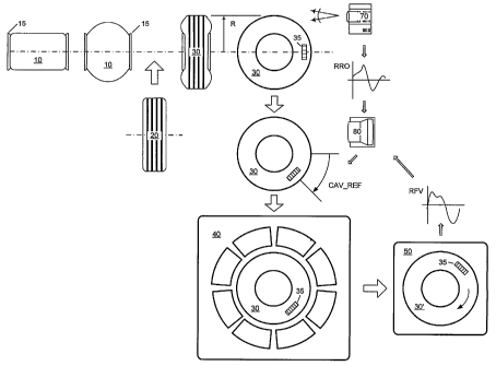
[0021] Fig. 1 is a schematic representation of a tire manufacturing process
equipped to practice the
method of the invention.
[0022] Fig. 2A - Fig 2C depict schematic representations of a uniformity
measurement of the radial
force variation of a tire showing the original composite waveform as well as
several harmonic
components.
[0023] Fig. 3 is a vector polar plot of the method of the invention showing
the contributions of the
tire room and curing room vectors to the after cure radial force variation of
a tire.
[0024] Fig. 4 is a vector polar plot of the method of the invention
demonstrating the optimization of
cured tire uniformity.
[0025] Fig. 5 is a vector polar plot of the method of the invention showing
the contribution. of green
tire radial runout to the tire room effect vector.
[0026] Fig. 6 is a vector polar plot of the method of the invention showing
the effect on the green tire
vector of the measurement drum used to measure green radial runout.
[0027] Fig. 7 is a vector polar plot of the method of the invention adding the
effect of the after cure
uniformity measurement machine.
[0028] Fig. 8 is a vector polar plot of an expanded method of the invention
showing the effect on the
green tire vector of additional components effects due to green tire carcass,
the tread and belt assembly,
and for the tooling effects of First Stage drum, the Tread and Belt Assembly
drum, and the Transfer Ring.
[0029] Fig. 9 is a vector polar plot of an expanded method of the invention
demonstrating the
optimization of cured tire uniformity.
DETAILED DESCRIPTION
[0030] Reference will now be made in detail to exemplary versions of the
invention, one or more
versions of which are illustrated in the drawings. Each described example is
provided as an explanation
of the invention, and not meant as a limitation of the invention. Throughout
the description, features
illustrated or described as part of one version may be usable with another
version. Features that are
_g_
CA 02545217 2006-05-08
WO 2005/051640 PCT/US2004/039021
common to all or some versions are described using similar reference numerals
as further depicted in the
figures. The following Table 1 indicates the specific terminology employed
herein. Note that the
CBD REF, FBD REF, SBD REF, TSR REF, and CAV REF are scalar quantities for the
reference
angles that are recorded during the tire manufacturing steps.
Table 1- Vector
Nomenclature
Vector Ma nitude Azimuth
Radial Force VRM1 VRA1
(VRHl)
Carcass Green FRM1C FRA1C
RRO
(GRl C)
Gain Carcass GC 8C
(GNC)
Tread Green RRO FRM 1 T FRA 1 T
(GR1T)
Gain Tread (GNT)GT 8T
Green Tire RRO FRM1 FRAl
(GRl)
Gain (GN) GN B
First Stage ToolingTMl TAl
(Tl)
Second Stage TM2 TA2
Tooling
(T2)
Tread and Belt TM3 TA3
Assembly (T3)
Transfer Ring TM4 TA4
Tooling
(T4)
Interce t (I IM 1 IA 1
l )
Tire Room EffectTRMI TRA1
(TRl)
Curing Room EffectCM1 CA1
(CRl )
First Stage Loading- - CBD_REF
An le
Second Stage - - FBD_REF
Loading
An le
Tread And Belt SBD_REF
Assembly Loading
Angle
Transfer Ring - - TSR_REF
Loading Angle
Curing Cavity - - CAV_REF
Loading Angle
[0031] Modern pneumatic tires are generally manufactured with great care and
precision. The tire
designer's goal is a finished tire that is free of non-uniformity in either
the circumferential or the lateral
directions. However, the designer's good intentions notwithstanding, the
multitude of steps in the tire
manufacturing process can introduce a variety of non-uniformities. An obvious
non-uniformity is that the
tire may not be perfectly circular (radial runout or RRO). Another form of non-
uniformity is radial force
_g_
CA 02545217 2006-05-08
WO 2005/051640 PCT/US2004/039021
variation (RFV). Consider a tire mounted on a freely rotating hub that has
been deflected a given distance
and rolls on a flat surface. A certain radial force reacting on the flat
surface that is a function of the
design of the tire can be measured by a variety of known means. This radial
force is, on average, equal to
the applied load on the tire. However, as the tire rolls, that radial force
will vary slightly due to variations
in the internal tire geometry that lead to variations in the local radial
stiffness of the tire. These variations
may be caused on the green tire by localized conditions such as product joints
used in the manufacture of
the green tire or inaccurate placement of certain products. The process of
curing the tire may introduce
additional factors due to the curing presses or slippage of products during
curing.
[0032] Figure 1 shows a simplified depiction of the tire manufacturing
process. A tire carcass 10 is
formed on a building drum 15. In a unistage manufacturing process, the carcass
10 remains on the drum
15. In a two-stage process, the carcass 10 would be removed from the drum 15
and moved to a second
stage finishing drum (not shown). In either case, the carcass 10 is inflated
to receive a finished tread band
20 to produce the finished green tire 30. In one variation of the invention,
the RRO of the green tire 30 is
measured by a measurement system 70 using a barcode 35 as a reference point.
The RRO waveform is
stored, here in a computer 80. The green tire 30 is moved to the curing room
where the orientation angle
of the tire CAV REF is recorded. The tire is then loaded into a curing cavity
40 and cured. The cured
tire 30' is moved to a uniformity measurement machine 50 for measurement and
recording of the tire
RFV.
[0033] Figure 2A shows a schematic of the measured RFV for a cured tire 30'.
The abscissa
represents the circumference of the tire and the ordinate the radial force
variations. Figure 2A is the as-
measured signal and is referred to as a composite waveform. The composite
waveform may comprise an
infinite series of harmonics. The individual harmonics may be obtained by
applying Fourier
decomposition to the composite signal. Figures 2B and 2C depict the resulting
first and second
harmonics, respectively, extracted form the composite signal. The magnitude of
the first harmonic of
radial force VRM1 is defined as the difference between the maximum and minimum
force. The phase
angle or azimuth of the first harmonic VRA1 is defined as the angular offset
between the reference
location for the measurement and the location of maximum radial force. Thus,
the sine wave depicted by
Cartesian coordinates in Fig. 2B can be equally shown as a vector in a polar
coordinate scheme. Such a
-10-
CA 02545217 2006-05-08
WO 2005/051640 PCT/US2004/039021
vector polar plot is shown in Fig. 2C immediately to the right of the sine
wave plot. The RFV vector of
the first harmonic VRHl has a length equal to VRMl and is rotated to an angle
equal to the azimuth
VRAI. In a similar manner, one Ican extract the second harmonic vector VRH2
shown in Fig. 2C that has
a force magnitude VRM2 and an azimuth VRA2. The corresponding polar plot for
the H2 vector
resembles the H1 vector, except that the angular coordinate is now two times
the azimuth angle.
[0034] In the description of an example of the method that follows, the
particular example is
confined to the optimization of the first harmonic Hl. However, it is within
the scope of the present
invention to apply the method to optimize a different harmonic such as H2, H3,
etc. Likewise, the
following example describes the optimization of radial force variation,
whereas it is within the scope of
the invention to apply the method to the correction of other uniformity
characteristics such as cured tire
radial runout or lateral force variation. In brief, the method may be used to
optimize the harmonics of any
measurable uniformity characteristic with suitable modifications to the vector
equations described below.
[0035] Figure 3 is a vector polar plot showing the two major contributions to
first harmonic of the
after cure radial force variation, the tire room effects vector TRI, and the
curing room effects vector CRl
when no optimization has been applied. The cured tire result VRH1 is the
vector sum of these two
components. A unique attribute of the invention is the ability to optimize the
after cure uniformity by
manipulation of these two component vectors. The ability to treat these
effects in vector space is possible
only when each harmonic has been extracted.
[0036] Figure 4 now shows a schematic of the optimization step. In this view
the green tire 30 has
been physically rotated by a pre-determined angle CAV REF so that its tire
room effect vector (TRl')
now directly opposes the curing room effect vector CRl, the latter being fixed
if there are no changes to
the setup or state of the curing equipment 40. It is readily apparent that
this optimization greatly reduces
the after cure result VRHl'.
[0037] The foregoing is a greatly simplified view of the factors affecting
after cure uniformity. Both
the tire room and curing room component vectors are the result of many
individual factors, or sub-vectors.
Each sub-vector is a contribution to the cured tire RFV and these vectors have
units that correspond to
radial force variation, i.e. kilograms. Figure 5 demonstrates one such sub-
vector, the effect of green tire
-11-
CA 02545217 2006-05-08
WO 2005/051640 PCT/US2004/039021
radial runout indicated as GRl *GN. This sub-vector represents the vector
product of the green RRO
(mm) and a gain vector that models the localized radial stiffness (Kg/mm).
However, the gain vector is
not a simple scalar factor as used in previous methods, but is a true vector
that accounts for
circumferential radial stiffness variation around the green tire 30. The
remaining, unidentified factors are
consolidated in the Intercept vector I1. If all factors were known, then the
Intercept vector I1 would not
exist. Throughout this disclosure, the Intercept vector I1 accounts for the
unidentified effects.
[0038] Figure 6 further declinates the tire room sub-vectors showing a first
representation of the
tooling effects. The measurement of green tire RRO is preferably at the
completion of tire building and
before the green tire is removed from the building drum 15. By way of
illustrated examples, the
measurement drum is the tire building drum 15, the single drum of a unistage
machine, or the finishing
drum of a two-stage machine. The green tire RRO measurement may also be
performed offline in a
dedicated measurement apparatus. In either case, the radial runout of the
measurement drum can
introduce a false contribution to the Green RRO vector. When the green tire
RRO is measured, the result
is the sum of true tire runout and the runout of the drum used for measurement
of RRO. However, only
the green tire RRO has an affect on the after cure RFV of the tire. As shown
in Fig. 6, the method of the
invention includes a sub-vector T2 due to the measurement drum to account for
this false RRO effect.
[0039] The sub-vector advantage can also be use to improve the curing room
effects. An effect
similar to the foregoing false RRO exists for measurement of after cure RFV.
That is, the measurement
machine itself introduces a contribution to the as-measured tire RFV. Figure 7
depicts an additional sub-
vector UM1 to account for this effect showing the difference between the
measured radial force vector
VRHl and the true radial force vector TVRHl. This sub-vector imparts a small,
but significant correction
to the rotation angle CAV REF shown in Fig. 4 for optimizing VRHl. Studies
have shown that the
inclusion of the UMl sub-vector can improve the magnitude VRMl of the true
radial force vector VRHl
by about 0.5 to 1.0 Kg. '
[0040] The foregoing graphical representations in vector space can now be
recast as equation (1)
below where each term represents the vectors and sub-vectors shown in the
example of Fig. 6. The
method can be applied to additional effects not depicted in Fig. 6 nor
described explicitly herein without
departing from the scope of the invention.
-12-
CA 02545217 2006-05-08
WO 2005/051640 PCT/US2004/039021
VRH1 = Tire Room RHl + Curing Room RH1 (1)
Substituting the sub-vectors for the tire room yields the final modeling
equation:
VRH1 = (Tire Room RHl + Building Drum + Intercept) + Curing Room RHl (2)
or
VRHI = GRl *GN + T2 + Il + CRl (3)
[0041] The first step in implementation of the method is to gather data to
build the modeling equation.
The Green RRO and VRHl vectors are measured quantities. The challenge is to
estimate the gain vector
GN, the building drum vector T2, the intercept vector I1, and the curing room
effect vector CRl. This is
accomplished by vector rotation and regression analysis.
[0042] First, a reference point on the tire, such as a barcode applied to the
carcass or a product joint
that will be accessible through then entire process is identified. In the
specific example described herein,
the invention contains an improvement to account for the radial runout of the
measurement drum itself.
This effect may be significant when the tire building drum 15 is used as the
measurement drum. The
loading angle FBD REF of the tire carcass on the measurement drum is recorded.
For this specific
example, the loading angle is measured as the carcass 10 is loaded on either
the first stage of a unistage or
a second stage of a two-stage machine. It is advantageous to ensure a wide
variation of the loading angle
FBD REF within a given sample of tires to ensure accurate estimation of the
effect of the measurement
drum runout on the vector coefficients.
[0043] Next, the RRO of the finished, green tire 30 is measured by a
measurement device 70 while the
tire is mounted on the finishing stage building drum 15. Alternatively, the
finished, green tire may be
moved to separate measurement apparatus and the RRO measurement made there.
This RRO
measurement is repeated for multiple tires to randomize the effects that are
not modeled. There are many
known devices 70 to obtain the RRO measurement such as a non-contact system
using a vision system or
a laser. It has been found that systems for measurement of radialrunout that
are based on tangential
imaging are preferred to those using radial imaging. The RRO data thus
acquired are recorded in a
computer 80.
-13-
CA 02545217 2006-05-08
WO 2005/051640 PCT/US2004/039021
[0044] Next, each green tire 30 is transferred to the curing room and the
identification of the curing
cavity 40 where each green tire is to be cured or vulcanized is recorded as
well as the orientation azimuth
CAV REF at which each green tire is loaded into the curing cavity. It is
advantageous to ensure a wide
variation of the orientation azimuth within a given sample of tires to ensure
accurate estimation of the
curing cavity effect on the vector coefficients. After each tire has been
cured, the cured tire 30' is moved
to the uniformity measurement machine 50 to acquire the radial force variation
RFV for each tire. The
RFV data thus acquired are also recorded in a computer 80.
[0045] If the model is extended to include a uniformity machine sub-vector
UM1, then similar steps to
those outlined above for the building drum vector are applied at the
uniformity measurement machine. A
loading angle for the cured tire on the uniformity measurement machine UM REF,
similar to the second
stage carcass loading angle FBD REF, is recorded and stored in the computer 80
with the associated RFV
data for a sample of tires. The sub-vector UM1 can then be added to the model
using the same vector
analysis procedure as described herein to obtain the building drum sub-vector
T2. The model will contain
an additional pair of coefficients to obtain a magnitude UMMl and an azimuth
UMA1 of the sub-vector
UMl to improve the estimation of after cure RFV.
[0046] Once these data have been acquired for a suitable sample of tires, the
harmonic data are
extracted from the RRO and RFV waveforms. In the present example the first
harmonic data of the green
radial runout GRl (magnitude FRM1 and azimuth FRA1) and radial force variation
VRHl (magnitude
VRMI and azimuth VRA1), respectively are extracted and stored. Each vector in
equation (2) above has
a magnitude and an azimuth as previously defined.
[0047] To facilitate rapid application of equation (3) in a manufacturing
environment, it is
advantageous to use a digital computer to solve the equation. This requires
converting the vector
equations above to a set of arithmetic equations in Cartesian coordinates. In
Cartesian coordinates, each
vector or sub-vector has an x-component and a y-component as shown in the
example below:
VRHIx = (VRM1)*COS(VRA1), and VRHlY = (VRM1)*SIN(VRA1) (4)
where the parentheses indicate the scalar values of magnitude and azimuth of
the quantity within. In like
manner the independent factors are converted from polar to Cartesian
coordinates:
-14-
CA 02545217 2006-05-08
WO 2005/051640 PCT/US2004/039021
GRlx= FRM1COS(FRAl) (5)
GRl Y = FRM 1 ~ SIN(FRA 1 )
CAV REF x = COS(CAV REF) (6)
CAV REF Y = SIN(CAV REF)
FBD_REF x = COS(FBD_REF) (7)
FBD REF Y = SIN(FBD REF)
Ilx = IM1 ~COS(IA1) (8)
I1Y=IM1~SIN(IA1)
The dependent vector (VRHIx, VRHlY) is sum of the vectors in the equations
below.
VRHlX - GN~FRM1~COS(e+FRAI) + (9)
CM1~COS(CAl+CAV-REF) +
TMI~COS(TA1+FBD REF) +
IMI ~COS(IA1)
VRHlY = GN~FRMI~SIN(e+FRAl) +
CMlSIN(CAl+CAV REF) + (10)
TM1~SIN(TAl+FBD REF) +
IMl ~SIN(IAl)
Expanding these equations with standard trigonometric identities yields:
VRHlX - GN~ COS(e) ~ FRM1~COS(FRA1) - GN~ SIN(9) ~ FRM1~SIN(FRAI) +
CM1COS(CAl) ~ COS(CAV REF) - CM1~SIN(CA1) ~ SIN(CAV REF) +
TM1~COS(TA1) ~ COS(FBD REF) - TMl~SIN(TA1) ~ SIN(FBD REF) +
IMl ~COS(IAI)
VRHIY - GN~ COS(e) ~ FRM1~SIN(FRA1) + GN~ SIN(~) ~ FRM1~COS(FRA1) +
CM1~COS(CAl) ~ SIN(CAV REF) + CM1~SIN(CAl) ~ COS(CAV_REF) +
TM1~COS(TAl) ~ SIN(FBD REF) + TMI~SIN(TAl) ~ COS(FBD REF) +
- IMI~COS(IAl)
To simplify the expanded equation, introduce the following identities:
a = GN~ COS(A), b = GN~ SIN(A) (11)
c=CMl~COS(CAl), d=CM1~SIN(CAl) (12)
Substituting these identities into the expanded form of equations (9) and (10)
yields:
VRHlX - a ~ GRlX - b ~ GRlY +
c ~ CAV-REF X - d ~ CAV REF Y +
a ~ FBD REF X - f ~ FBD REF Y + ( 13 )
IlX
VRHlY - a ~ GRIy + b ~ GRIX +
c ~ CAV_REFY + d ~ CAV-REFX +
a ~ FBD REF Y + f ~ FBD REF X + ( 14)
-15-
CA 02545217 2006-05-08
WO 2005/051640 PCT/US2004/039021
IlY
The equations (13) and (14) immediately above can be written in matrix format:
a
b
c
VRHlx ~ = GRlx -GRlY CAV REFx -CAV REFY FBD_REFX -FBD_REFY 1 0 ~ d
VRHlY GRlY GRlx CAV REFY CAV REFx FBD REFY FBD REFx 0 1 a (15)
f
Ix
IY
When the predictive coefficients vectors (a, b), (c, d), (e, f), and (Ilx,
IlY) are known, the equation (15)
above provides a modeling equation by which the VRHl vector for an individual
tire may be estimated.
This basic formulation can also be modified to include other process elements
and to account for different
production organization schemes. These coefficient vectors may be obtained by
various known
mathematical methods to solve the matrix equation above.
[0048] In a manufacturing environment, and to facilitate real-time use and
updating of the
coefficients, the method is more easily implemented if the coefficients are
determined simultaneously by
a least-squares regression estimate. All coefficients for all building drums
and cavities may be solved for
in a single regression step. Finally, the vector coefficients are stored in a
database for future use. For the
example of a single mold and single curing cavity, the coefficients have a
physical significance as
follows: (a, b) is the gain vector GN in units of kgf/mm, (c, d) is the curing
room effect vector CRl in
units of kgf, (e, f) is the building drum vector T2 in units of kgf, and (Ilx,
IlY) is the Intercept vector I1 in
units of kgf.
[0049] The equations listed above are for one curing cavity and one building
drum. The curing
cavity and building drum are nested factors meaning that although the actual
process contains many
building drums and many cavities, each tire will see only one of each. Thus
the complete equation may
include a vector for each building drum and each curing cavity as shown below.
Expanding the model
first requires the creation of the following matrices Va, C;,;, and X,~, where
the subscript "i" denotes mold
i and the where the subscript "j" denotes building machine drum j, the
subscript pair "i~j" denotes a tire
manufactured on building drum "j" and cured in curing cavity "i":
-16-
CA 02545217 2006-05-08
WO 2005/051640 PCT/US2004/039021
a
b
c
~RMlx
I ''' hRMl C''' a
Y
Ilx
IlY
FRMlx -FRMlY CAIr-REFx -CAY-REFY FBD_REFx FBD_REFY 1 0
~''' FRMlY FRMlx CAV-REFY CAV-REFX FBD-REFY FBD-REFx 0 1
Then the equations above can be expressed in the succinct matrix form below
for a given combination of
mold and building machine drum (indexed by i and j):
>J ~t>.l X CI>J (16)
This equation can be expanded to accommodate multiple molds and multiple
building machine drums
simultaneously in matrix formula below:
Y>, X,,, 0 . . 0 ~ 0 . . 0
Y>2 0 Xl,z . . 0 0 . . 0 Cl>2
T;>m = 0 0 . . Xl>n, 0 . . 0 x C (18)
l,m
Y2,1 0 0 . . 0 tY2,1 . . 0 CZ>1 ,
~n>»~ 0 0 . . 0 0 0 0 X",m C'n~n:
-17-
CA 02545217 2006-05-08
WO 2005/051640 PCT/US2004/039021
[0050] The final step is to apply the model to optimize the RFV of individual
tires as they are
manufactured according to the illustration shown in Fig. 4. Each tire building
drum carriers an
identification "j" and each curing cavity an identification "i." Each tire
carries a unique identification
device, such as a barcode. These identification tags allow the information
recorded for an individual tire
to be retrieved at a later step. At the completion of tire building, the green
RRO is measured and its
harmonic magnitude FRMl and azimuth FRA1 are recorded along with the loading
angle FBD REF of
the tire on the building or measurement drum. When the green tire arrives in
the curing room, the curing
cavity in which it will be cured will be predetermined and the curing room
effect vector information for
that cavity may be retrieved from the database. A reading device scans the
unique barcode to identify the
tire, to facilitate polling the database to find the measured and recorded
tire information: FRM1 and
FRA1, the building drum identification, and the loading angle FBD REF. Next, a
calculation is
performed to estimate the tire room effect vector by the equations below. Note
that equations (17) and
(18) are identical in form to equations (9) and (10) above, but now axe being
used in a predictive fashion
to estimate the tire room contribution to cured RFV.
TRlX - a ~ GRlX - b ~ GRlY +
a ~ FBD REF X - f ~ FBD REF Y + ( 19)
IlX
TRlY - a ~ GRlY + b ~ GRlX +
a ~ FBD_REF y + f '~, FBD REF X +
Il,~ (20)
The azimuth TRA1 of the tire room effect vector TRl is the inverse tangent of
the quantity (TRlY/TRlX),
and the azimuth CA1 of the curing room effect vector CA1 is the inverse
tangent of the quantity (d/c).
Again referring to Fig. 4, the green tire 30 is rotated so that its
orientation angle CAV REF relative to the
curing cavity 40 is such that azimuth TRA1 of the predicted tire room effect
vector is opposed to the
azimuth CAlof the curing room effect vector. This operationmay be expressed
inthe equation below:
CAV REF = 180 + TRA1- CAl (21)
The green tire 30 is then loaded into the curing cavity 40 at the orientation
angle CAV REF that
minimizes RFV in the cured tire 30'.
-18-
CA 02545217 2006-05-08
WO 2005/051640 PCT/US2004/039021
[0051] When the above method is practiced with multiple tire building drums
and multiple curing
cavities, then all steps of the method, determining the vector coefficients,
estimating the after cure RFV,
and optimizing the after cure uniformity, are carried out using the specific
identifiers of the ~ process
equipment. In this manner, a tire produced on any building machine can be
cured in a curing cavity with
an optimized level of RFV.
[0052] In the case where the tire does not have a unique identifying barcode,
it is not possible to
perform the entire optimization process at the curing room. In this case, the
tire must be marked to
indicate the azimuth TRAl of the tire room effect vector TRl while the tire is
at the tire building
machine. The azimuth of the tire room effect vector of the green tire is
calculated using the vector-
regression method, and a mark is placed on the tire corresponding to the
azimuth angle TRA1. In
addition, the curing cavity 40 has been previously marked at an azimuth (CA1-
180) diametrically
opposed-to the curing room effect vector CAl. When the green tire 30 is
transferred to the curing room
and arrives at the curing cavity 40, the pre-applied mark on the tire 30
indicating the azimuth TRA1 is
aligned with the pre-applied mark on the curing cavity 40. In this manner, the
tire room effect vector TRl
and the curing room effect vector oppose each other and the after cure VRHl
will be optimized.
[0053] Another advantageous and unique feature of the invention is the ability
to update the
predictive coefficients vectors (a, b), (c, d), (e, f), and (IX, IY) with the
data measured from each individual
tire to account for the constant variations associated with a complex
manufacturing process. Because the
green RRO and cured RFV of individual tires are continuously measured, the
model may be updated at
periodic intervals with these new production data to adjust the predictive
equations for changes in the
process. These updates may be appended to the existing data or used to
calculate a new, independent set
of predictive coefficient vectors that may replace the original data.
[0054] Figure 8 is a vector polar plot of an expanded method of the invention
showing the effect on
the green tire vector GRl *GN of additional components effects due to green
tire carcass, the tread and
belt assembly, and for the tooling effects of first stage drum, the tread and
belt assembly drum, and the
transfer ring. This may be accomplished through suitable modifications of the
foregoing system of vector
equations. The green tire effect vector GRl *GN is now capable of being
described by the component
-19-
CA 02545217 2006-05-08
WO 2005/051640 PCT/US2004/039021
sub-vectors corresponding a set of tire component sub-assemblies and a set of
tooling effects. The green
tire vector GRl *GN now appears as:
GRl *GN = GR1C*GNC + GR1T*GNT + T1 + T3 + T4 (22)
The vector equation (3) which describes the estimated tire room effect vector
TRl becomes:
TRl = GR1C*GNC GRIT*GNT + T1 + T2 + T3 + T4 + Il (23)
and the estimated after cure uniformity remains as in equation (1)
VRHl = TRl + CRl (24)
where TRl is now represented by the new equation (23). One skilled in the art
may follow the same
methodology as described previously in the vector equations (4) through (15)
to expand the set of
predictive equations to correspond to the expanded tire room vector equation
(23). The result below
shows the x and y components of RFV: .
VRHlX - a GR1CX - b GR1CY + (25)
c GR1TX - d GR1TY +
h CBD REF - j CBD REF +
X Y
k FBD REF - m FBD REF +
X Y
n SBD REF - p SBD REF +
X Y ,
q TSR REF - r TSR REF +
X Y
s CAV REF - t CAV REF +
X Y
Ilx
VRHlY - a GR1CY + b GR1CX + (26)
c GR1TY + d GR1TX +
h CBD REFY + j CBD REFX +
k FBD REF + m FBD REF +
y X
n SBD REF + p SBD REF +
Y X
q TSR REFY + r TSR REFX +
s CAV REF + t CAV REF +
Y X
IlY
A multiple linear regression routine is used to estimate simultaneously
coefficients vectors (a, b), (c, d),
(h, j), (k, m), (n, p), (q, r), (s, t), and (Ilx, IlY). The vector
coefficients have a physical significance.
The vector (a, b) is the carcass gain vector GC and will be in units of
kgf/mm. The vector (c, d) is the
tread and belt assembly gain vector GT and will be in units of kgf/mm. The
vector (h, j) is the first stage
building drum tooling vector T1 and is in units of kgf. The vector (k, m) is
the second stage building
drum tooling vector T2 and is in units of kgf. The vector (n, p) is the tread
and belt assembly building
-20-
CA 02545217 2006-05-08
WO 2005/051640 PCT/US2004/039021
drum tooling vector T3 and is in units of kgf. The vector (q, r) is the
transfer ring tooling vector T4 and
is in units of kgf. The vector (s, t) is the curing room effect vector CRl and
is in units of kgf. The vector
(Ilx, IlY) is the interceptwector and is in units of kgf.
[0055] Following the procedural steps previously described, the expanded model
may be practiced in
the following illustrative manner. In the step of determining the vector
coefficients, the method is
practiced as previously described, but with additional steps. For example, if
the model is to include the
first stage building drum sub-vector T1, then it will be necessary for the
data on the sample of tires to
include a recording of the carcass loading angle on the first stage drum CBD
REF. Likewise to account
for the green tire carcass sub-vector GR1C and the carcass gain GNC, a
measurement of the RRO of the
green carcass is necessary. Here the term carcass means the components of the
green tire minus the tread
and belt assembly. This is often a sub-assembly from the first stage of a two
stage building process.
Likewise the tread and belt assembly sub-vector GRIT and tread gain GNT can be
included through
measurements of the tread and belt assembly loading angle SBD REF of these
tire components on a form
commonly used to build this assembly, followed by a measurement of the green
RRO of the assembly on
' the building form. Lastly, the transfer ring tooling effect T4 accounts for
uniformity effects introduced by
the apparatus use to transfer the tread and belt assembly 20 from the building
form to a position to be
joined with the green carcass. The tooling effect T4 is accounted for by a
measurement of the loading
angle in the transfer ring TSR REF.
[0056] These tires are then cured in a curing mold as before, followed by
measurement of the after
cure RFV. The unknown coefficients for the series of sub-vectors are
determined in a simultaneous step
from a regression analysis. Finally, once the sub-vector coefficients are
known, the equations are used in
a predictive manner. Figure 8 graphically illustrates the result of equation
(22) where the additional sub
vectors provide an alternative means by which to estimate the tire room effect
vector TRl for an
' individual tire.
[0057] The model is then applied to optimize the after cure RFV of an
individual tire. The steps
described herein apply to a two-stage building process where the carcass and
tread and belt assemblies are
built as separate components, and then joined to complete the tire. It is
within the scope of the invention
S
to apply the method to other tire building methods. Specifically the
optimization of these tire building
-21-
CA 02545217 2006-05-08
WO 2005/051640 PCT/US2004/039021
steps will be performed using the coefficient derived in the model building
step. Using the tooling effects
and the measured radial runout effects, the optimal relative angles of loading
of the carcass 10 and the
tread and belt assembly 20 will be generated and either marked on the elements
or preferably
automatically rotated to the selected angles by machine control systems. At
the start of tire building, the
first stage building drum identification is recorded, followed by building the
carcass. Next, the carcass
RRO measurements are made on the first stage drum and the carcass effect
vector GR1C*GC is
computed. The tooling contribution is known through the tooling vector T1.
Alternatively, the carcass
RRO measurements may be made on the second stage building drum, in which case
the tooling vectors
r
T1 and T2 may be used. The tread and belt assembly steps begin with recording
the building from
identification, followed applying the belts and the tread band. Next, the
tread and belt assembly RRO is
measured on the form and tread and belt assembly effect vector GRIT*GT is
computed. The tooling
contribution of the building form is known through the tooling vector T3.
Finally, one records the
information to identify the second stage building drum, the transfer ring
drum, and the respective tooling
vectors T2, and T4.
[0058]' The optimization method may be applied in several variations depending
on the level of
sophistication of the manufacturing equipment. For the example shown in Fig.
1, the equipment allows
labeling of the tire components for identification and azimuth. The equipment
also allows for selection of
curing molds and for loading of the tire in a curing mold at an azimuth
orientation determined form the
model. In this instance, the after cure RFV is reduced by building a green
tire 30 having a magnitude of
the tire room effect vector TRl equal or nearly equal to the magnitude of the
curing room effect vector
CRl. Figure 9 represents this variation. The optimized tire room effect vector
TRl is now shown as a
dotted line to demonstrate the matching of its magnitude to that of the curing
room effect vector CRl . In
particular, Figure 9 further demonstrates that the manipulation of the green
tire effect vector GR1C*GN,
also show by a dotted line. When the tire is thereafter match loaded in the
curing mold, the two effects
are nearly equal and opposite, and the after cure RFV is minimized. In
practice, the errors in
measurement and in the accuracy of the model are such that one would not
expect to produce a tire with
zero after cure RFV. If the manufacturing equipment is less sophisticated and
does not permit the match
-22-
CA 02545217 2006-05-08
WO 2005/051640 PCT/US2004/039021
loading in the curing mold, then the optimization may be used simply to
minimize the tire room effect
vector TRl alone.
[0059] The optimization method is applied similarly for both the preceding
examples. First, an
optimization criterion is chosen depending on the manufacturing environment.
In the first of the
examples above , the intended curing mold is known and its respective curing
room effect vector CRl is
known. The optimization criterion is the magnitude CM1 of the curing room
effect vector CRl. In the
second of the examples above, the optimization criterion is set to any desired
level. For example, to
minimize the tire room effect vector TRl, the optimization criterion is set to
zero.
[0060] The optimization method is used to determine an optimum set of loading
angles on the
second stage building drum FBD REF and the transfer ring TSR REF to produce a
tire with the
predetermined value of CM1. The curing room azimuth angle CAV REF is
simultaneously determined
for future use. The vector system just described forms a response surface for
the estimated tire room
effect vector TRl as a function of the component sub-vectors. The response
surface may have a single
maximum or several local maxima. It has been found that the optimized solution
can be efficiently
i
determined using a well-known non-linear, steepest descent method based on
commercially available
code. As employed in the method, the steepest descent routine is run using
more than one set of starting
values to increase the likelihood that the best solution is obtained. Other
optimization methods are
possible such as quadratic optimization, linear descent, or even an exhaustive
search. The next steps are
to complete the tire 30 according to the optimized loading angles. The tread
and belt package 20 is
loaded on the summit transfer ring at the predeteunined angle TSR REF, and the
carcass 10 is loaded on
the second stage building drum at the predetermined angle FBD REF. The carcass
10 can then be
inflated and joined to the tread and belt assembly 20 to complete the green
tire 30. As an optional step for
verification, the before cure RRO of finished tire can be measured to assess
the robustness of the model.
In a final step, the green tire 30 is moved to the curing room and then loaded
into the curing cavity 40 at
the azimuth angle determined from CAV REF that minimizes RFV in the cured tire
30'. Experimental
results obtained during the verification of the method have shown that the
present invention is able to
account for a significantly higher percentage of the cure tire RFV than
previous methods used in with the
similar manufacturing processes.
-23-
CA 02545217 2006-05-08
WO 2005/051640 PCT/US2004/039021
[0061] When the method is applied to minimize only the tire room effect vector
TRl, the
optimization routine determines angles FBD REF and TSR REF. The carcass 20 and
tread and belt
package 20 are loaded at these predetermined angles to finish the tire 30. In
a final step, the green tire 30
is moved to the curing room and then loaded into any curing cavity 40 without
attention to the loading
angle in the cavity 40.
[0062] It should be understood that the present invention includes various
modifications that can be
made to the tire manufacturing method described herein as come within the
scope of the appended claims
and their equivalents.
-24-