Note: Descriptions are shown in the official language in which they were submitted.
CA 02545486 2006-05-02
A SYSTEM FOR DETECTING AND ANALYZING BODY MOTION
Field of Invention
The present invention relates to sensor systems for
performing functional assessments of biomechanics.
Background of the Invention
A capacity assessment (also referred to as a
functional capacity evaluation of biomechanics (FAB) or
functional capacity evaluation (FCE)) is a test of a
person's ability to perform functional activities in order
to establish strengths and weaknesses in executing daily
activity. Functional activities are defined as meaningful
tasks of daily living, including personal care, leisure
tasks, and productive occupation. Productive occupation
does not strictly mean paid employment. Productive
occupation can be any daily activity that occupies time
including housework and yard work.
Presently there is no practical system available for
sensing biomechanics or body positions during testing,
rehabilitation, and daily tasks. Traditionally a
therapist, physician or chiropractor observes a patient and
assesses biomechanics and body positions through best guess
techniques, which is an imprecise and time-consuming
process. Further, once information is gathered there is
usually a slow and cumbersome process of incorporating data
into formal reports.
CA 02545486 2006-05-02
In order to obtain the type of data needed to conduct
a capacity assessment, body movements must be measured
simultaneously in 3 planes, namely, frontal, sagittal and
transverse (e. g. lower back movements) (see Fig. 1). Body
motion tracking is often limited to laboratories equipped
with camera-based tracking systems (see, for example,
systems developed by Human Performance Labs, and area-
limited performer-trackers, such as those of Ascension
MotionStar). Because of the complex optical environment
required, measurements outside of the laboratory are
notoriously difficult. Portable solid-state angle sensors
such as those employing accelerometers - although accurate
for static measurements - are not suitable for body motion
tracking. They are highly sensitive to the accelerations
associated with normal human movement. There are inherent
problems with trying to measure relative position and
absolute velocity with these types of sensors without
correcting for inertial effects (in the case of
accelerometers) and integration offset (in the case of
gyroscopes). Accordingly, there is a need in the art for a
comprehensive tool to augment capacity and disability
testing by sensing body positions and movements over
extended periods of time.
A portable device that could be attached to a part of
the body and accurately measure its orientation could have
numerous applications.
Summary of the Invention
The present invention is a portable sensor system that
allows a Functional Capacity Evaluation to be efficiently
2
CA 02545486 2006-05-02
and accurately performed on a patient. The invention is
herein referred to as the FAB System. The present
invention uses 3D sensors located at various predetermined
points on the patient's body, and collects data on the
frequency and nature of the movements over extended periods
of time (e. g. from 8 up to 35 hours).
The present. invention comprises, in part, a novel
acceleration-insensitive, three-dimensional angle sensor
employing magnetometers, accelerometers and gyroscopes.
The angle sensor, in conjunction with a novel computation,
provides for accurate measurement of body position. The
gyroscope angular velocity measurements - unaffected by
acceleration - are used to continuously rotate a matrix
that represents the orientation of the sensor. The
magnetometer and accelerometer measurements are used to
construct a second matrix that also estimates the sensor's
orientation - unsusceptible to the drift introduced by
integrating the gyroscope signals. The first matrix is
~~pulled" slightly towards the second matrix each step of
the computation, thereby eliminating drift. The result is
a high-bandwidth orientation sensor that is insensitive to
acceleration.
The 3D sensor performs acceleration measurement along
3 axes, inertial (gyroscopic) measurement along 3 axes, and
magnetic measuz°ement along 3 axes. Several different
embodiments of the 3D sensor are contemplated. For
example, since some commercially available accelerometers
and magnetometer chips have 2 axes per chip, one economical
embodiment of the 3D sensor is made up of 2 accelerometers,
3 gyroscopes, and 2 magnetometers (i.e. only 3 of 4
3
CA 02545486 2006-05-02
available accelerometer and magnetometer axes would be
used) . Alternat:ively, the 3D sensor could be built using 3
accelerometers, 3 gyroscopes and 3 magnetometers, each
having one axis. In each of these embodiments the 3D
sensor is capable of performing acceleration, gyroscopic
and magnetic measurements along 3 axes.
The primary application of the invention is in the
diagnosis and rehabilitation of orthopaedic injuries such
as fractures and connective tissue injuries such as back
injuries or shoulder injuries. However, the invention can
also be used for neurological injuries such as stroke or
nerve injuries. The invention generally has application in
medical conditions where there is restricted movement of
the arms (shoulders), spine, legs, or feet.
The 3D sensors of the present invention have numerous
potential medical and non-medical applications.
It is envisioned that the invention will be used
primarily in rehabilitation clinics, work places, and at
home. For example, if a housewife were in a motor vehicle
accident and had a whiplash injury with back pain, the
sensors could be used to monitor movement while at home.
However, the system can generally be used as necessary in
any setting or environment.
In a preferred embodiment there are 4 sets of paired
sensors, one pair for the feet, one for the legs, one for
the spine, and one for the arms. The sensors on the legs,
lumbar spine, and the arms are 3D sensors. The foot
sensors are pressure sensors. The invention can be used
4
CA 02545486 2006-05-02
with either a partial or a full complement of sensors so
that end users can purchase, use and/or configure the
invention as needed.
More sensors can be added to obtain more detail about
the movements of various parts of the body. For example,
sensors could be placed on the ankles, on the wrists,
between the shoulder blades, on the back of the neck and/or
head, etc. The number and placement of the sensors is a
function of the type and amount of data needed.
The data provided by the 3-D sensors is processed
according to algorithms that calculate the path-independent
angles between any two 3-D sensors.
Brief Description of the Drawings
Further features and advantages will be apparent from
the following Detailed Description of the Invention, given
by way of example, of a preferred embodiment taken in
conjunction with the accompanying drawings, wherein:
Figure 1 shows the frontal, sagittal and transverse
planes and axes;
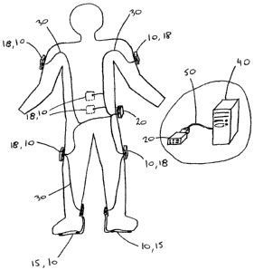
Figure 2 is a diagram of a preferred embodiment of the
invention as worn by a patient;
Figure 3 shows layout of a preferred embodiment of the
3D sensor;
5
CA 02545486 2006-05-02
Figure 4 shows a 3D sensor attached to a patient's
leg;
Figure 5 shows angles sensed by an accelerometer-based
sensor placed above a patient's knee, 40 cm from the point
of rotation;
Figure 6 shows the angle sensed by a gyroscope-based
sensor for a patient moving his leg between 0 degrees and
90 degrees at 30 repetitions per minute;
Figure 7 shows a plot of estimated and actual angles
of a patient's 1_eg moving between 0 and 90 degrees;
Figure 8 shows a plot of patient's leg moving between
0 and 90 degrees;
Figure 9 shows a general architecture of the FAB
Software;
Figure 10 illustrates definitions of angles of the
patient's arms in the frontal and sagittal planes;
Figure 11 illustrates definitions of angles of the
patient's arms in the transverse plane;
Figure 12 illustrates rotation of a vector r about n
by the finite angle ~; and
Figure 13 illustrates the spherical angles of a
patient's arm.
6
CA 02545486 2006-05-02
Detailed Description of the Invention
The system consists of a number of sensor units 10 and
a belt-clip unit 20, as shown in Figure 2. All of the
sensor units 10 are connected to the belt-clip unit either
wirelessly or by cables 30. In a preferred embodiment EIA
RS-485 is used as the physical communication layer between
the units. There are two types of sensor units 10, foot
sensors 15 and 3D sensors 18.
A patient will wear the system for an assessment
period, which is 1_ong enough for the system to gather the
required amount of data. Although the system may be worn
by a patient for periods of up to 24 hours or more,
(depending on available battery power and memory) it is
contemplated that assessment periods will generally be up
to about 8 hours long. Data can be gathered over several
assessment periods.
Data collected during an assessment period is stored
in the Belt Clip 20 and can be subsequently transferred to
a computer 40. In one embodiment, data is transferred by
connecting an EIA RS-232 serial cable 50 between the Belt
Clip 20 and the computer 40. Alternatively, the data can
be stored on a memory card, which can be used to transfer
the data to a computer.
Sensors
3o In the embodiment of Figure 2, all sensor units 10 are
connected directly to the Belt Clip 20 via combined
RS-485/power cables 30. Each sensor unit 10 has an on-
7
CA 02545486 2006-05-02
board microprocessor, and is powered and controlled by the
Belt Clip 20. Data from the sensor units 10 is sent to the
Belt Clip 20 over the RS-485 signals in real time.
All of the sensor units 10 are able to sense and
record duration and number of repetitions of movements. In
order to detect rapid movements, sensor units 10 must be
able to provide readings or measurements more than once a
second. In the preferred embodiment the sensor units 10
provide readings 25 times per second to the Belt Clip 20.
In a preferred embodiment the invention is modular in
the sense that it is made up of a number of interchangeable
sensor units 10 (although the foot sensors 15 are obviously
not interchangeable with the 3D sensors 18 because they
perform different functions). End users can configure the
system according to their needs or for a particular
application by adding or removing sensor units 10.
In an alternate embodiment the system is wireless and
the individual sensor units 10 are connected to the Belt
Clip 20 by 900 MHz or 2.4 GHz transceivers. The
transceivers of the wireless embodiment replace the cables
used in the embodiment of Fig. 2. Additional minor
25 modifications may be necessary in the wireless embodiment,
for example to the communications protocols to accommodate
for the imperfect nature of wireless communications. In
addition, each wireless sensor unit will have its own
battery and power management hardware and/or software.
8
CA 02545486 2006-05-02
Foot Sensors
In the preferred embodiment sensors are placed under
each foot to measure weight and pressure. The foot sensors
15 are able to sense pressure in both the heel and ball of
the foot. The foot sensors 15 precisely measure applied
pressure. Depending on the way the patient's weight is
distributed on his or her feet, the pressure reading may or
may not directly translate to an accurate weight reading,
however, the pressure readings will be consistent.
The foot sensors 15 are flat. Each foot sensor 15
will consist of an ankle "bracelet" (attached to the ankle
with a Velcro° strap) containing the electronics and an
attached flexible "tongue". The tongue contains the
pressure sensors to be placed under the sole of the foot,
normally inside a shoe.
I~eg, Arm and Back Sensors
Each "3D" sensor 18 (that is, a sensor that is not a
foot sensor 15) is a device that is designed to sense yaw,
pitch and roll relative to the earth, with no physical
attachment to the ground. Each 3D sensor 18 comprises
components that allow it to measure each of rotational
velocity (gyrosc:opes), gravitational pull (accelerometers),
and the earth's magnetic field (compasses), in three
orthogonal directions x, y and z (see Fig. 3). The sensor
components are mounted such that all three are measured
along the same x, y and z axes. Commercially available
accelerometers and compasses generally have two axes each,
therefore, two accelerometers 60 are sufficient to cover
9
CA 02545486 2006-05-02
the 3 axes in the embodiment of Fig. 2. The embodiment of
Fig. 2 has three gyroscopes 70 and two compass chips 80.
Theoretically, for the 3D sensors 18 all that would be
needed would be gyroscopes 70 to measure movement, since
position is the time-integral of velocity (and therefore
can be calculated from velocity data). However, real
gyroscopes aren't perfect and their readings always contain
drift and offset from zero. Additionally, the Earth's
Coriolis effect will give a small, but nevertheless non-
zero reading even if the sensor is stationary.
Depending on the specific components used to construct
a sensor 18 according to the present invention,
sensitivities of the sensors 18 may vary (e. g. certain
motions or signals may have to be filtered out in the
hardware and/or software, and/or delays may have to be
introduced).
Preferably, all components are placed as close to one
another as possible to reduce ~2r acceleration. If possible
the lines through the centers of the gyroscopes 70 and
accelerometers 60 are perpendicular to their surfaces and
intersect at a common point (see Fig. 3).
Leg Sensors
A leg sensor is placed on the right and left thighs
proximal to the knee (see Figs. 2 and 4). The leg sensors
accurately measure angles relative to gravity in the
l0
CA 02545486 2006-05-02
sagittal plane. The leg sensors are attached to the thighs
with Velcro" straps or other suitable means.
Arm Sensors
In the preferred embodiment, (Fig. 2) arm sensors are
attached to the arms just above the elbow on the lateral
side (outside). The arm sensors accurately measure angles
relative to gravity and magnetic North in the sagittal,
frontal and transverse planes. The arm sensors are
attached to the arms with Velcro straps or other suitable
means.
Back Sensors
The back sensors consist of two or more units which
are capable of measuring angles in the sagittal, frontal
and transverse planes. Measurement in the transverse plane
poses a challenge because gravity cannot always be used as
a reference. In fact, any movement in a plane
perpendicular to gravity poses the same challenge.
The back sensors must be able to measure and record
the range of motion of the following movements:
i. flexion (forward bending);
ii. extension (backward bending);
iii. lateral flexion (sideways bending); and
iv. rotation (twisting to the right or left).
In the preferred embodiment one of the back sensors is
placed at the vertebral level of Thoracic 12-Lumbar 1 (T12-
11
CA 02545486 2006-05-02
Ll) and the other back sensor is placed at the vertebral
level Lumbar 5-Sacral 1 (L5-Sl).
The back sensors measure range of motion which is
defined as the difference in the angle between the lower
sensor and the upper sensor. For example, if in flexion
the lower sensor moves 5° and the upper sensor moves 60°,
then the flexion of the back is 55° (i.e. the pelvis tilted
5° and the back flexed 55° to result in a 60° change in
position of the upper sensor).
The back sensors are able to detect combined movements
(e. g. when a patient's back is simultaneously extended
backwards, (i.e. in the frontal plane) twisted, and flexed
laterally) .
One measurement plane of the back sensors will almost
always be perpendicular to gravity when the patient is in
the in the normal (erect) body position. Therefore, non-
gravitational sensing devices (e.g. gyroscopes) must be
employed along with advanced mathematical techniques to
achieve practical measurements in the transverse plane.
The sensors are attached to the lower back using a
flexible adhesive, (such as a suitable adhesive tape)
keeping in mind that it is desirable for the sensors to
remain firmly attached during moderate perspiration. The
present invention endeavours to minimize interference with
normal patient activities and range of motion.
12
CA 02545486 2006-05-02
Belt Clip
The Belt Clip 20 is a compact unit containing
batteries, a microprocessor, data memory and a serial
interface. In the embodiment of Fig. 2 power is fed to all
the sensors 10 from the Belt Clip 20. The Belt Clip 20 is
able to power itself and all th.e sensors 10 continuously
for 10 hours without having to change the batteries (in a
wireless embodiment each of the sensors would have its own
battery) .
The microprocessor serves to collect data, in real-
time, from all the sensors 10 and to store the raw
information in i.ts data memory. The contents of the Belt
Clip's data memory can be transferred to a computer 40 via
the serial interface, 50 which in the embodiment of Fig. 2
is a RS-232 interface (alternatively, a memory card such as
a Secure Digital card may be used). The Belt Clip 20 has
indicator lamps and/or buttons to indicate its operating
status and facilitate calibration.
Adding up all the data from the sensors, 10 a large
amount of information streams into data memory in the Belt
Clip 20 every second. Although it would be technically
possible to perform robotics (e.g. yaw, pitch, roll) and
other (e.g. angl_es between sensors) calculations in the
sensors' and/or Belt Clip's microprocessors, the sheer
volume of data, coupled with the complexity of the
computations, means that the necessary components would
significantly drive up the cost of the invention.
Accordingly, in the preferred embodiment, the data is
stored in the data memory in the Belt Clip 20 for post-
13
CA 02545486 2006-05-02
analysis. Real-time positional data would also be possible
with, for example, a fast RF link to a personal computer
where the data could be analyzed in real time.
An audible alarm is incorporated to indicate status
changes and fault conditions (e.g. alerting the user of a
low-battery or detached-wire condition).
The Belt Clip 20 is configured for a sensor "suite" by
connecting all the sensors 10 in a desired configuration
and executing a "configure" command via a specific button
sequence. Thus, the patient cannot inadvertently leave out
a sensor 10 when collecting data for the assessor.
A calibration is performed to establish a baseline for
the sensor readings. This step can be performed by
standing in a pre-defined position, and giving a
"calibrate" command via the buttons. The calibration must
be performed prior to collecting data, but may be performed
additionally during data collection as desired.
The Belt Clip 20 will start collecting data from the
sensors 10 once it is switched on, a calibration is
performed, and a "start" command is given via the buttons.
Data collection will stop if a "stop" command is given.
Preferably, the stop command requires either a verification
step or other mechanism to prevent accidental deactivation.
The Belt Clip 20 contains enough data memory to store,
for example, 40 continuous hours of sensor information.
These 40 hours may be split into multiple "sessions",
separated by "stop" and "start" commands. The data
l4
CA 02545486 2006-05-02
analysis software is able to distinguish one session from
another.
Once data has been collected, the data is transferred
to a computer. Once the data has been transferred, the
data memory may be cleared with a file-operation command on
the computer.
In the preferred embodiment the data memory retains
its contents even if the system is shut off and/or the
batteries removed.
Interconnections
In the embodiment of Fig. 2, mufti-conductor
RS-485/power cables 30 are used to interconnect the sensors
10 and Belt Clip 20. The cables 30 may be simply run under
clothing, or secured to the body with Velcro° straps and/or
adhesive tape.
In the preferred embodiment the cables 30 terminate in
connectors, to allow modularity and flexibility in the
configuration of the cable "network". For example, cables
may be star-connected to the Belt Clip 20 and/or daisy-
25 chained as desired.
Firmware
Firmware for the Belt Clip 20 and each sensor enables
30 data collection, system communication and system error-
checking. The firmware is the ~~brains" of the system and
enables the sensors 10 to send data to the Belt Clip 20 by
CA 02545486 2006-05-02
creating a two-way communications protocol over the RS-485
cables 30.
The Belt Clip firmware may have a data-transfer
protocol for the RS-232 interface or a filesystem for the
memory card. The firmware also performs checks on the data
and hardware to ensure that faults are clearly identified.
These checks help avoid collecting useless information in
the event there is a system fault.
Sof tware
The computer software collects the data stored in the
Belt Clip 20, and performs mathematically-complex
processing in order to interpret the data. The data will
be stored on the computer hard disk, and displayed in a
meaningful manner to the assessor (e. g, therapist).
The computer software interprets the measured data as
physical body positions (i.e. standing, sitting, walking,
etc.) and displays both the interpreted and raw data in
tabular and graphical formats. The software can determine
the number of repetitions performed for a variety of
defined movements, the range of motion of the defined
movements, the speed of movement, average or mean time
spent in defined positions and/or performing defined
movements, total time spent in defined positions and/or
performing defined movements, maximum and minimum amounts
of time spent in defined positions and/or performing
defined movements, etc.
16
CA 02545486 2006-05-02
The data may additionally be stored in a relational
database (RDB). This allows data to be organised, indexed
and searched in a flexible manner. Additionally, third-
party software can be used to generate reports from the
data.
The following is a specification of a prototypical
embodiment of a software program (referred to throughout as
the FAB Software) for implementation of the invention. The
FAB Software program is used to display information
collected from the FAB system sensors. The FAB Software
interacts with the Belt Clip of the FAB system and obtains
recorded sensor readings, interprets the readings and
displays the information in a meaningful manner. The
following description of the FAB Software is intended only
as a description of an illustrative embodiment. The
following description is not intended to be construed in a
limiting sense. Various modifications of the illustrative
embodiment, as well as other embodiments of the invention,
will be apparent to persons skilled in the art upon
reference to this description.
FAB Software Architecture
The FAB Software will be a program, running on a
personal computer (PC), that facilitates the interface
between the end user and the collected data from the Belt
Clip and sensors. The FAB Software is written in an
object-oriented manner and is event driven. Events are
generated by the user's interaction with the software's
graphical user interface (GUI). Object-oriented
17
CA 02545486 2006-05-02
programming helps to modularize the code making it clean
and easy to understand which eases software enhancements in
the future.
A general architecture of the FAB Software is shown in
Fig. 9. The major components of the FAB Software are
described in the following subsections.
Graphical User Interface (GUI)
The GUI portion of the FAB Software is built into a
familiar WindowsTM based framework with all the necessary
displays and controls.
The GUI is also the event driver for the FAB Software.
In an event driven program, all program executions occur as
a result of some external event. In our case, the user is
the only source of events and causes events only through
interaction with the GUI portion of the FAB Software.
Belt Clip Interface
The FAB Software includes an interface to the FAB
system's Belt Clip to be able to read the raw data
collected by the Belt Clip. Herein, raw data is referred
to as collected data in the form that it is received from
the Belt Clip.
For the purposes of setting the Belt Clip's date and
time clock, the FAB Software communicates with the Belt
Clip via a Serial Port Interface that provides services for
accessing the PC's serial port. The FAB Software's GUI
provides the user a means of choosing either COM1 or COM2.
18
CA 02545486 2006-05-02
Raw data stored by the Belt Clip is organised into a
number of sessions, each session being stored as a file.
After all the ra.w data from a particular session has been
obtained the Belt Clip Interface triggers the Data
Interpretation Module to interpret the raw data.
Interpreting data
After the Belt Clip has finished downloading a session
it triggers the Data Interpretation module to interpret the
raw data into physical body positions.
There are two stages involved in interpreting the
data, a transformation stage and an interpretation stage.
Data Transformation
The raw data obtained from the Belt Clip will be raw
sensor readings. These data readings must be transformed
through complex differential equations to obtain the actual
angle and pressure readings.
Data Interpretation
The resulting angle and pressure data obtained through
the data transformation stage is interpreted to obtain
physical body positions.
19
CA 02545486 2006-05-02
Data Storage
A relational database can be used to store both the
raw data and the interpreted body positions. Each session
can be contained in a single database.
Exporting Data
The FAB Software is able to export data tables as
comma-separated variable (CSV) files, which are compatible
with many other applications including Microsoft Excel.
Additionally, it may be possible for third-party software
to read data directly from the database.
Example Definitions of Angles and Positions
As used herein, the terms flexion and extension refer
to movement of a joint in the sagittal plane. Abduction
and adduction refer to movement of a joint in the frontal
plane .
The angles of the legs are only in the sagittal plane
and are relative to gravity. When the leg is in the
neutral position parallel to gravity the angle is defined
to be 0°. The l.eg is defined to have a positive angle when
it is angled forward in front of the body. The leg is
defined to have a negative angle when it is angled
backwards behind the body.
CA 02545486 2006-05-02
The angle of the back is defined to be negative in the
sagittal plane when the back is bent forward and positive
when the back is bent backwards.
The angle of the back is defined to be positive in the
frontal plane when the back is bent to the right hand side
and negative when the back is bent to the left hand side.
The angle of the back is defined to be positive in the
transverse plane when the back is twisted to right and
negative when the back is twisted to the left.
The arms in the frontal plane are defined to be 0°
when the arms are in their neutral position parallel to the
torso of the body. Positive angles are defined when the
arms are raised to the sides as shown in Figure 10(a).
When the arms are crossed in front of the body the angles
are defined to be negative in the frontal plane.
The arms in the sagittal plane are defined to be 0°
when the arms are in their neutral position parallel to the
torso of the body. Positive angles are defined when the
arms are raised forward in front of the body as shown in
Figure 10(b). When the arms are raised backwards behind
the body the angles are defined to be negative in the
sagittal plane.
The angles of the arms in the transverse plane are
defined to be 0° when the arms are directly out in front of
21
CA 02545486 2006-05-02
the body. Positive angles are defined when the arms are
angled to the sides of the body as shown in Figure 11.
Negative angles are defined when the arms are angled across
the front the body.
For all arm angles the left and right arm angles are
measured independently and relative to the body torso as
opposed to gravity.
Regardless of the embodiment of the invention that is
being used, a number of postures, positions and/or
movements will have to be defined so that, given a set of
angle and weight pressure data, meaningful data analysis
can be performed. The following are example definitions:
Sitting:
Less than l00 of body weight on the feet
Right or left leg at 60° to 110°
Standing:
~ Right and left leg at ~10°
Full weight on the feet
Two-point Kneeling, Position 1:
Less than 5o weight on the feet
Both legs at 0° to 15°
Two-point Kneeling, Position 2:
Less than 5% weight on the feet
Both legs at 45° to 55°
22
CA 02545486 2006-05-02
One-point Kneeling on right knee:
Right leg at ~10°
Left leg at 75° to 110°
5o to 750 of weight on left foot
One-point Kneeling on left knee:
Left l.eg at ~10°
Right leg at 75° to 110°
5% to 75a of weight on right foot
Crouching:
~ Full weight on the feet
Both legs at 75° to 115°
Walking:
Alternate weight bearing between feet
At alternate times full weight is on each foot
IS ~ Legs alternating at least ~10°
The angular position of the arms are defined to be
relative to the person's torso position and therefore the
position of the arms are defined as follows:
Sagittal Angle of Arms:
i Sagittal angle of arms relative to gravity minus
sagitt;al angle of upper back.
23
CA 02545486 2006-05-02
Frontal Angle of Left Arm:
Frontal angle of left arm relative to gravity
minus frontal angle of upper back.
Frontal Angle of Right Arm:
~ Frontal angle of right arm relative to gravity
plus frontal angle of upper back.
Transverse Angle of Arms:
r~ Transverse angle of each arm relative to magnetic
North minus transverse angle of upper back.
In addition. to the above body positions, a "calibrate"
position may be defined to be a person standing straight
with legs directly underneath the body and arms hanging
freely on the sides. This position can be used to
establish what sensor readings correspond to zero angles.
Further definitions will be readily apparent to
persons skilled in the art.
Portable Three-Dimensional Angle Sensor
The following methodology assumes that each 3-D sensor
18 includes:
(a) 2 ~2g dual-axis accelerometers (ADXL202E or
similar) ;
(b) 3 ~300°/s single-axis rate gyroscopes (ADXRS300 or
similar); and
(c) 2 dual-axis compass chips.
24
CA 02545486 2006-05-02
Preferably, a_Ll components are placed as close as
possible to one another to reduce ~2r acceleration. In
addition, lines extending through the centers of the gyros
70 and accelerometers 60 perpendicular to their surfaces
should intersect at a common point, as shown in Fig. 3.
To perform a assessment of biomechanics, the angles
between various joints on the human body must be accurately
measured. It is common practice to measure angles relative
to the direction of gravity using accelerometers. This
method works particularly well in devices such as digital
levels because the level is completely stationary when the
angle measurement is taken. However, if a sensor is
required to measure the angle of a patient's hip as he
moves his leg up to 90 degrees and back down, (see Fig. 4)
the sensor must compensate for the acceleration of the hip-
mounted sensor. Fig. 5 shows the ~~angle" that would be
sensed (solid line) by an accelerometer-based sensor if a
patient's hip were moved from the vertical position of 0
degrees to a horizontal position of 90 degrees at the
indicated repetition rate (10, 30, 48 and 120 repetitions
per minute). It. is assumed that the sensor is placed near
the patient's knee, 40 cm from the point of rotation (see
Fig. 4).
The difficulty with using a gyroscope to measure
angles is that t;he gyroscope outputs a signal proportional
to the rate of change of the angle. The signal must be
integrated to get an angle measurement. The main problem
that arises from this is that any zero-point offset
produces an error that grows linearly in time. Eventually,
one loses track of the absolute angle measurement.
CA 02545486 2006-05-02
Referring to Fig. 6, wherein the solid line represents the
"angle" sensed, the angle calculated by a gyroscope-based
sensor can be simulated for a patient moving his leg
between 0 degrees and 90 degrees at 30 repetitions per
minute. For the sake of simplicity it is assumed that
there is a I o of c~~"aX (2. 8 ~ /s) offset and a I o slope error
(due to perhaps linear acceleration or inaccuracy in the
device). The angle estimate obtained using the gyroscope-
based sensor is very different from what was obtained using
an accelerometer. The AC component is much more accurate
except there is DC drift.
In the FAB sensor I8 of the present invention, both AC
accuracy and DC stability are required. The following
discussion describes how a gyroscope can be used in
conjunction with an accelerometer to create a sensor I8
with good AC accuracy and no DC drift.
In the acceleration-tolerant angle sensor I8 of the
present invention, a gyroscope is used for AC angle
accuracy and an accelerometer is used to provide "feedback"
that ensures DC stability. To estimate the angle, a method
not unlike integral control is used. The estimate of the
tilt angle, 8(t), is defined mathematically as follows:
8 (t) - ,f~c~ (t) dt + k ,fe (t) dt,
where
.i0 a (t) - 6a (t) - 6 (t) ,
and
26
CA 02545486 2006-05-02
6a (t) - arctan (dx/dy) .
The estimate of the tilt angle, 8(t), is equal to the
integral of the angular velocity signal from the gyroscope
plus a term proportional to the integral of the ~~error".
Error in this sense is a misnomer: it is defined as the
angle approximation from the accelerometers, 6a(t), minus
the estimate of the tilt angle 8(t). There is no guarantee
that at any point in time 6a(t) is a better approximation of
the tilt angle than 8 (t) , it is simply that 6a (t) is
guaranteed to have no drift.
This angle estimation method can be applied to the
case of a patient's leg moving between 0 and 90 degrees
(see Fig. 4). fig. 7 shows a plot of the estimated angle
(solid line) versus the actual angle (dashed line) at
various values of k . Except for the first graph, all
graphs show the estimated angle (solid) versus the steady-
state results. In the first graph, there is no steady-
state because th.e error in the estimated angle drifts
linearly with time.
At low values of k, the steady-state error is
inversely proportional to k and directly proportional to
the offset in the gyroscope output. At high values of k,
the sensor behaves like a pure accelerometer-based angle
sensor. The optimum value for k therefore depends on how
good the accelerometer estimate of the angle is and how
small the drift in the integrated gyroscope angle estimate.
A small offset i.n the gyroscope output and a poor
accelerometer estimate would suit a small value for k. A
27
CA 02545486 2006-05-02
large offset in the gyroscope output and an excellent
accelerometer estimate would suit a large value for k.
These effects are shown graphically in Fig. 8.
These results show how a gyroscope and accelerometer
can be used together to measure tilt angles in a way that
is neither sensitive to acceleration of the sensor nor
sensitive to offset in the gyroscope signal. The sensor
tracks the tilt angle with AC accuracy similar to a pure
gyroscope-based angle sensor and the DC stability of a pure
accelerometer-based tilt sensor.
Computation
The present invention comprises, in part, a high-
bandwidth, acceleration-insensitive, three-dimensional (3D)
orientation sensor 18. The invention utilizes sensors 18
having orthogonal magnetometers, accelerometers, and
gyroscopes (see Fig. 3) and a novel computation to convert
the readings into a 3x3 matrix that represents the
orientation of the sensor relative to earth. The
computation is based on using the gyroscopes to quickly
track angular changes and then accelerometers and
magnetometers to correct for any drift encountered through
the gyroscope "i.ntegration" process.
As the computation makes extensive use of rotation
matrices, a review of their characteristics is provided
below in sections labeled I-V.
Section I provides a review of the characteristics of
rotation matrices and Section II provides a description of
28
CA 02545486 2006-05-02
how gyroscopes can be used to track changes in 3D angular
position: each step of the computation the gyroscope
angular velocity readings are used to rotate the
orientation matrix by the amount implied by the readings.
Although this technique produces excellent angular and
temporal resolution, it suffers from drift.
Section III describes how accelerometers and
magnetometers can be used to redundantly estimate the
angular position of the sensor: after readings from these
devices are used to estimate the gravity and magnetic field
vectors, a Gram-Schmidt process is applied to construct a
matrix that also estimates orientation. Although this
method is highly sensitive to spurious accelerations, it
does not suffer from drift.
Section IV discloses how data from gyroscopes,
accelerometers, and magnetometers can be processed together
to achieve high-bandwidth, acceleration-insensitive, drift-
free angle measurements. The algorithm is based on
tracking the orientation of the sensor with the gyroscopes
but also "pulling" the orientation matrix slightly towards
the accelerometer/ magnetometer estimation each step of the
computation.
Section V provides a description of some of the testing
that has been completed and limitations of the device.
I. The Linear A7_aebra of Orientation Matrices
Three-dimensional rotation or "orientation" matrices
are used extensively in the computation. The symbol R is
29
CA 02545486 2006-05-02
used to denote all such matrices. To describe what an
orientation matrix is, assume that there exist two frames:
Frame 0 and Frame A. Frame 0 is the reference frame from
which the orientation of Frame .A is measured. The
following matrix specifies the orientation of Frame A with
respect to Frame 0:
Frame measured from ~ 0 R ( 1 )
A f- Frame being measured
The superscript to the left denotes the frame in which
the orientation is measured from; the subscript to the
right denotes the frame being measured. R is a 3x3 matrix
whose columns represent vectors in Frame 0 aligned along
the coordinate axis of Frame A. For example, the first
column represents a vector in Frame 0 aligned along the x-
axis of Frame A. Correspondingly, the rows of this matrix
represent vectors in Frame A aligned along the coordinate
axes of Frame 0. Because of this property of the matrix,
its transpose specifies the orientation of Frame 0 as
measured from Frame A:
T R° = Transpose( ° RT ) ( 2 )
Now suppose that there exists a second Frame B and its
orientation is known with respect to Frame 0. Its
orientation with reference to Frame A is then
ARs = ARo oRs . ( 3 )
Note the cancellation of the adjacent 0's.
CA 02545486 2006-05-02
In the angle sensor calculation described in the
following sections, Frame 0 is used to denote a reference
frame fixed on earth, Frame A is used to denote the
sensor's frame, and Frame B is used to denote the sensor's
orientation as implied by the accelerometer/magnetometer
readings. Certain orientation matrices are used
extensively and are given names other than R: matrix A
denotes the orientation of the sensor (Frame A) measured
from earth, in other words
A=°R.a ~ (4)
Matrix B denotes the orientation as specified by the
accelerometer/magnetometer readings (Frame B) measured from
earth:
B= °RB - (5)
Matrix S specifies the orientation of Frame B with
respect to Frame A:
S - "R~ = A R° °RB = ATB . ( 6 )
Finally, the matrix
1 -dSZr d S2 y,
f R r+o (due) = d ~~ 1 -dS2X ( ~ )
-dS2 v dS2.r 1
denotes the orientation of a frame rotated infinitesimally
from the (arbitrary) frame f about the vector dS~ by an
31
CA 02545486 2006-05-02
angle (in radians) equal to the magnitude of the vector.
The proof follows easily by considering infinitesimal
rotations about each of the axes, and also observing that
the sequence is unimportant for infinitesimal. rotations.
It is clear that all 9 parameters in the orientation
matrices are not independent degrees of freedom. By
viewing the rotation matrix as 3 column vectors
representing the rigid coordinate axes, then each of these
vectors must have unit length and each of these vectors
must be orthogonal to the others. These conditions impose
6 constraints on the 9 parameters resulting in 3 degrees of
rotational freedom, as expected. Following from these
properties, the matrices are orthogonal and normal: the dot
product of any column with any other column, or any row
with any other row is zero. The sum of the squares of any
column or row as well as the determinant is unity.
A common method of specifying the orientation of a
frame with 3 parameters is to use yaw-pitch-roll Euler
angles. The yaw, pitch and roll angles can be thought of
as instructions for how to rotate a frame initially
coincident with the reference frame to its new orientation.
This convention assumes first a counterclockwise rotation
about the reference frame's z-axis by the yaw angle
followed by a counterclockwise rotation about the
intermediate y-axis by the pitch angle 8, followed by a
counterclockwise rotation about the new x-axis by the roll
angle ~. The Euler angles can be found by performing the
following trigonometric operations on the elements of the
rotation matrix:
32
CA 02545486 2006-05-02
~ = arctan(Rz~, Ru)
8 = arctan(-R3 ~, Rza + Ra~ ) . ( 8 )
tV = arctan(R3~, R33)
The arctan(y, x) function is the four-quadrant inverse
tangent and Rid is the element of R in the ith row and jth
column.
II. Gyroscope Orientation Tracking
Rotation About a Fixed Axis
Gyroscopes provide accurate angular velocity
information from which angular displacement can be
determined. In the case of rotation about a fixed axis,
the rotation angle 8 as a function of time can be found
directly with the integration
e(r)-ao= ~~(t)dr .
The integration is often performed discretely, in which
case the relation for 8 becomes
8.+~=C~r4t+8; . (10)
where coy is the angular velocity averaged for at least twice
the length of the sampling period to satisfy the Nyquist
criteria.
Two limitations inherent i.n gyroscope-based angle
33
CA 02545486 2006-05-02
sensors can be seen. First, an initial angle is required
to start the procedure; if this angle is incorrect, then
future angle measurements will likewise be incorrect.
Second, during each step in the procedure a small amount of
error is compounded to the angle estimation. Even if the
errors are completely random, the angle measurement will
undergo a random walk and deviate until it becomes
meaningless.
3-D Rotation
When the a~:is of rotation is not fixed, the process of
updating the sensor orientation becomes more involved. The
novel method developed involves tracking the orientation
matrix A (defined in Section I, above). The orientation of
A is updated each step of the computation via
multiplication with the infinitesimal rotation matrix
~ Aa+~ _ ~ Aa a Ra+o ~d~) ( 11 )
The vector dS2 = (dS2X dS2Y dS2Z) T points along the
instantaneous axis of rotation, has magnitude equal to the
total angle of rotation, and is related to the average
angular velocity during the time interval in question:
dS2X C~x,
dS2k = dS2~ = 4t ~y, ( 12 )
dS2~ co ,
The superscript g is used to indicate that this
rotation vector is due to the gyroscopes (and will become
34
CA 02545486 2006-05-02
important in Section IV, below). To carry out this
calculation,.a controller may poll the three gyroscopes to
determine dS2g, multiply the A matrix by the infinitesimal
rotation matrix implied by dS2g, and finally update A by
setting it equal to the product.
III. Accelerometer/Maanetometer Orientation Estimation
Heading and Tilt Angle Measurements
For measuring heading, two orthogonal magnetometers
with axes in a plane parallel to the horizontal are often
used. For measuring tilt angle, two orthogonal
accelerometers with axes in a plane perpendicular to the
horizontal are typically employed. In both cases, an angle
relative to magnetic north (heading) or vertical (tilt) can
be determined by appropriately taking a four-quadrant
arctangent of the two orthogonal sensor readings.
3-D Angle Measurements
For measuring the complete 3D angular orientation of a
static body, three perpendicular accelerometers and three
perpendicular magnetometers are required (see Fig. 3). For
present purposes>, the simplification will be made that
earth's magnetic: field points due north.
To describe the calculation, first define an
orthogonal coordinate system (i.e. a reference frame) that
is fixed with the earth such that the x-axis points east,
CA 02545486 2006-05-02
the y-axis points north, and the z-axis points up. Next
define an orthogonal coordinate system that is fixed with
the sensor consisting of axes x', y', z'. Assume that a
magnetometer as well as an accelerometer is aligned along
each of the sensor's coordinate axes.
Each accelerometer reads the component of the
reference frame's z-axis (i.e. up) aligned along its axis.
Defining aX~, ay~ and aZ~ as the accelerometer readings along
the respective sensor axes, the vector
aX~
a= ay~ (13)
a:
then approximates the direction of the earth's z-axis as
measured in the sensor's frame.
Similarly, each magnetometer reads the component of
the earth's magnetic field aligned along its axis.
Defining bX~, by~ and bz~ as the magnetometer readings along
the respective sensor axes, the vector
bX
b= bY~ (14)
b~
then approximates the direction of earth's magnetic field
as measured by the sensor.
As customary, define i, j, k as three unit vectors
36
CA 02545486 2006-05-02
along the x, y, and z axes of the reference frame fixed on
earth. Since a and b are not guaranteed orthogonal
(because the magnetic field vector may point into the
ground and the gravity vector may be affected by
acceleration), i, j, k must be approximated using the Gram-
Schmidt process:
bxa
i=
bxa
_ axi (15)
axil
k=ixj.
It is crucial that the gravity vector is used in the second
step of Eq. (15) to prevent problems associated with the
inclination of earth's magnetic field. If a matrix is
constructed using the unit vectors to form the columns,
then the matrix will represent the orientation of the
earth's reference frame as measured by the sensor, i.e. BR°.
It is more convenient to know the orientation of the sensor
with respect to the reference frame, i.e. °RB or B. The
unit vectors form the rows of this matrix (via the
transpose property of orientation matrices)
ix, iy, i,,
B = ~i j k)T Jx~ Jv~ J
kx, kY~ k ,
The primary problem with this type of accelerometer-
based sensor is that it is sensitive to acceleration. In
the non-accelerating case, the apparent acceleration is due
37
CA 02545486 2006-05-02
only to gravity and the vector points straight up.
However, in the accelerating case, this vector is
completely arbitrary and the estimation of "up" is
meaningless.
IV. Hybrid Solution
The pure gyroscope computation requires information
that describes the initial 3D orientation of the sensor -
it is not self-stabilizing. In fact it is unstable: the
angular measurements drift without bound from even the
smallest measurement errors. The
magnetometer/accelerometer method has the advantage of
stability. However, since the assumed direction for "up"
is based on the accelerometer readings, it is strongly
influenced by any acceleration experienced by the sensor.
A method that combines the high-bandwidth,
acceleration-insensitive angle measurements of the
gyroscope technique with the stability of the
accelerometer/magnetometer technique is required if the
device is to be used to track human body orientation during
regular activities.
Computation Overview
In the hybrid solution the vector used to rotate the
orientation matrix is the sum of the rotation vector from
the gyroscopes and a vector that "pulls" slightly towards
the accelerometer/magnetometer orientation estimation. The
hybrid solution confers excellent sensitivity to small or
38
CA 02545486 2006-05-02
rapid changes in orientation and eliminates drift.
Computation Details
The computation of the hybrid solution executes at a
constant rate with frames separated by the time period 4t.
A 3x3 matrix denoted A (initially set to the identity
matrix) is used to track the orientation of the sensor.
The stability of the computation ensures that the A matrix
will converge to represent the correct sensor orientation.
Every sampling period, the angular velocity vector, w,
is measured using the onboard rate gyroscopes to calculate
the gyroscope rotation vector via Eqn. (11). To correct
for integration drift, A is rotated slightly towards the
feedback matrix B found from the compass and accelerometer
readings via Eqns. (13)-(16). Before the A matrix can be
rotated towards B, a vector specifying the desired
correction must be determined. The magnitude of this
rotation (the length of the desired vector) is proportional
to the total angle, ~, separating A and B.
Since S specifies the orientation of Frame B as
measured from Frame A, it must contain information about
the total angle of rotation between the frames as well as
the axis of rotation. It is always possible via a suitable
similarity transformation to change to a coordinate system
where the rotation S' is entirely about the new z-axis:
cos ~ sin ~ 0
S' _ - sin ~ cos ~ 0
0 0 1
CA 02545486 2006-05-02
The trace of S' is
TrS'=2cos~+1
but since the trace of a matrix is invariant under
similarity transformation
TrS=2cos~+1
solving for the total angle gives
~=arccos~Tr~ 11 (17)
where Tr() is th.e trace or the sum of the diagonal elements
of the matrix and S specifies the orientation of Frame B as
measured from Frame A as per Eqn. (6).
Consider the rotation of a vector r about n by the
finite angle ~. Referring to Figure 12, the rotated vector
r' can be described by the equation
r'=n(n.r)+[r-n(n~r)]cosh+(rxn)sin~
which after a slight rearrangement of the terms leads to
r'=rcos~+n(n~r)[1-cosh]+(rxn)sin~ . (18)
The formula can be cast into a more useful form by
CA 02545486 2006-05-02
introducing a scalar eo and a vector a with components el,
ez, and e3 defined as
cos ~
(19)
eo =
2
and
e-nsin~ . (20)
2
Since n =1, these four quantities are obviously related by
z
eo + a = eo + e; + e2 + e3 =1
It follows that
cos ~ = 2eo -1 .
and
2eo
n = a .
sin ~
With these results, (18) can be rewritten as
r' = r(eo - e~ - e2 - e3 ) + 2e(e ~ r) + 2(r x e)eo ( 21 )
Equation (21) thus gives r' in terms or r and can be
expressed as a matrix equation
41
CA 02545486 2006-05-02
r'=S~r
where the components of S follow from inspection
e~+e~ -e2-e3 2(e~e2+e~e3) 2(ele3-eQe~)
S = 2(elez-eDe3) e0-el +eZ-e3 2(e2e3+eQe~) .
2(e~e3+e~e2 ) 2(eze3 +eDe~ ) e~ -e~ -e2 +e3
Equations (17) and (19) can be used to solve explicitly for
eo, resulting in
eo= T~ +1 (22)
Knowing eo, the components of a can now be found by
examining the e7_ements of S. For instance, el can be found
noting that
Sz3 - S32 = 2(e2e~ + eoe,) - 2(eZe3 - eoeO
and then solving for eo
el = S23 - S3Z
4eo
After solving for e2 and e3 in the same manner, the vector a
can be constructed
Say - Ssz
e= 1 S3~-S~3 (23)
4eo
S~z -S2~
42
CA 02545486 2006-05-02
To find n rather than e, (17), (20) and (22) can be used to
eliminate the total angle and eo. The desired results
emerges:
Sz3 - S3z
n= 1 S3~-S~3 (24)
(1 + Tr S)(3 - Tr S)
Si2-Szi
where Sid is the element of S in the ith row and jth column.
The desired vector specifying the small rotation is thus
dSL° = k4t~n ( 2 5 )
where k is a gain parameter used to tune the feedback for
optimum performance. A larger value of k pulls the
orientation matrix towards the accelerometer/magnetometer
approximation quickly. For stability kit < 1. The
superscript c is used to indicate that this rotation vector
is the correction term.
Equation (25) can be written more explicitly using
Eqns. (16) and (24) as
c kOt arCCOS ( Trz ~ ) S23 - S32
d,S2, = S3~-S~3 (26)
(1+TrS)(3-TrS) S~~-Sz~
Since both rotation vectors dS2g and dS2~ are small, they can
be added to get the vector specifying the total rotation:
43
CA 02545486 2006-05-02
dSZ = dSL ~ + dSZ ° . ( 2 7 )
Since dS~ is also small, the infinitesimal matrix rotator,
(see Eqn. (7)) can be used to execute the rotation. The
new orientation of the sensor is therefore given by Eqn.
(11)
O AA+D ~ O AA A RA+A ~d~~ ~ ( 2 8 )
remembering that dS2 included both the gyroscope rotation
and a rotation towards the accelerometer/magnetometer
feedback matrix. This computation executes at a rapid rate
to accurately track the angular orientation of the sensor.
Since the rotation is not truly infinitesimal, it is
necessary to orthonormalize A occasionally via a Gram-
Schmidt process such as Eqn. (15). As the calculation
executes, A converges to the correct orientation at the
time constant k-1. After convergence, the columns of A
represent the sensors coordinate frame axes as measured in
the reference frame on earth.
Implementation Details
The choice of k depends on both how quickly the angle
measurements drift with zero feedback and how much
acceleration the sensor experiences. In a case where the
angle measurements drift slowly and the sensor experiences
a great deal of spurious acceleration, a very small time
constant is suitable and the sensor will behave more like a
pure gyroscope angle sensor. In the other extreme, where
44
CA 02545486 2006-05-02
the gyroscope angle measurements drift very fast and the
system is subject to negligible accelerations, a large
value of k is preferred and the sensor behaves similar to a
pure accelerometer/magnetometer angle sensor. Testing of a
prototype angle sensor gave best results with a time
constant of 2 seconds (k = 0.5).
To expedite the convergence of the A matrix, it was
found convenient to increase k at start up and allow the
computation to proceed with a large value for a couple of
time constants. Another implementation note is that
numerical precision effects will sometimes cause the trace
of the S matrix to lie outside the range of -1 to +3 and
thus cause the total angle of rotation to be imaginary.
Forcing the trace of S to be within its expected range
eliminated this problem. Finally, when calculating S one
has the choice c>f using the current B matrix or the
previous B matrix. This choice was found to be unimportant
and the most current matrix was used out of convenience.
A prototype sensor was built and used to test the
computation. The sensor readings were routed into a
computer, which then performed the calculation in real
time. The program converted the orientation matrix to yaw,
pitch and roll angles and displayed them in real time on
the screen. The sensor was held in a fixed position and
shaken to check the devices sensitivity to acceleration.
No noticeable ef=fect from the acceleration was present.
Relative Angle Calculation for the FAB System
CA 02545486 2006-05-02
This section presents the calculations used to extract
the body angles of a human subject wearing the FAB system
from the orientation matrices stored in each of the 3-D
angle sensors. The angles are reported "relative" to the
subject in a convenient way as to ease interpretation of
the data. Three-dimensional angle sensors, such as those
described above, can be mounted to a human patient and used
to track his motion. Because the human arms and legs
contain only revolute joints, their position is specified
by the angles of the limb segments or the joint
coordinates. 3-D angle sensors provide an orientation
relative to a fixed reference frame on earth. However, to
transform these absolute angle measurements into meaningful
joint coordinates, it is more useful to measure angles
relative to the human subject.
This section describes the relative angle calculation
performed in the Function Assessment of Biomechanics (FAB)
system. In the preferred embodiment the FAB system employs
six 3-D angle sensors attached to the patient's lower back,
spine, right and left upper arms, and right and left
thighs. Rather than reporting angles relative to the
earth, the FAB system processes the raw orientation data
from the sensors to calculate relative angles between body
parts. This provides information that specifies the
position of the person and their limbs in an easier-to-
understand format.
Section V describes the calculation used to determine
the relative orientation between two 3-D angle sensors.
Section VI then shows how the angles for all of the sensors
are calculated from these relative orientation matrices.
46
CA 02545486 2006-05-02
V. Relative Orientation Calculation
In the preferred embodiment, the FAB system monitors
the orientation of the patient's lower back, spine, right
upper arm, left upper arm, right thigh and left thigh using
six 3-D angle sensors. For the purposes of this section,
"patient position" refers to a point in 14-dimensional
hyperspace where each coordinate represents one of the
measured angles. Through the development of the present
invention, a means for presenting patient position in an
easily-understandable way was established. The concept
revolves around providing body angles relative to other
parts of the body. For example, the angles of the arm are
measured relative to the sensor mounted to the patient's
spine so that the arm angles read the same value when the
shoulder joint is in the same position, regardless of
whether the patient is standing straight or leaning
forward.
It was shown above that each angle sensor contains a
3x3 matrix that specifies its orientation relative to the
earth. To calculate the desired "relative" body angles, a
method must first be established for constructing a
relative orientation matrix for each sensor that specifies
its orientation relative to a second "reference" angle
sensor. The desired body angles can then be extracted from
these matrices using the four-quadrant arctangent function.
47
CA 02545486 2006-05-02
An Illustrative Example: Right Arm Orientation
As already mentioned, the orientation of the right arm
is measured relative to the spine. Let Frame 0 be the
earth frame, Frame SP be the spine sensor frame, and Frame
RA be the right arm sensor frame. Thus °RSP and °R~
represent the orientation of the spine and right arm frames
relative to earth, respectively. These are the
"orientation" matrices stored automatically by the sensors
according to the calculations in IV above. Naively, it
would seem that the desired "relative" orientation matrix
is the matrix that specifies the orientation of Frame RA
relative to Frame SP. However, this is not the case. It
is not known how the arm sensor will be attached to the
patient. The arm sensor must be "calibrated" so that the
relative orientation matrix is equal to the identity matrix
when the patient: is in the neutral position (standing tall,
arms by his side).
An additional frame that represents the calibrated arm
sensor, Frame RA-C, must be defined (the "-C" indicates a
calibrated frame). At calibration time, Frame RA-C is
defined to be coincident with Frame SP of the spine. What
happens, mathematically, is that this calibrated frame is
"glued" rigidly to Frame RA such that the two frames move
together. Body angles are then extracted from the
orientation of Frame RA-C so that the angles read zero at
the neutral position.
Since Frame RA-C is "glued" to Frame RA, it always has
48
CA 02545486 2006-05-02
the same orientation relative to Frame RA. The matrix ~R~_
describes thi~> relationship and can be thought of as the
calibration matrix. At calibration time, Frame RA-C is
defined to be coincident with Frame SP. From this fact,
the calibration matrix can be calculated
~ R,~~, _ ~~ RS,, _ ~ R° ° R SP (at calibration) ( 2 9 )
We know that ~'R° is the transpose of the A matrix for the
right arm sensor and °RSP is the A matrix for the spine
sensor (see sections I-IV above). We can write:
C = ~°A (at calibration) ( 3 0 )
RA RA SY
The over-tilde is used to represent the transpose of a
matrix. Now at. any subsequent time, the desired relative
angles will be contained in the matrix SPRR~,-c found via
sYR~-c = sYR° oR~~ aAR~-~ ( 31 )
which, using the notation from sections I-IV, is equivalent
to
R=~°AC (32)
XA SP RA RA
The underscript R is new notation: it represents the
relative orientation matrix that is actually used to
extract the body angles.
The calculation of the relative matrix for the other
49
CA 02545486 2006-05-02
sensors follows by replacing RA with the sensor in question
and SP with its reference sensor.
CA 02545486 2006-05-02
TABLE 1
Relative Angle Summary
Sensor Referenced Angle Equation Range Neutral
to position
Yaw/ ~ =arctan(R~z,Rzz) { 0,
Lower Earth heading 360}
back
Pitch e=arctan(R3z, R~z2+Rzz2){-180.
18 0 } Arms by
Roll yi=arctan(-R3~,R3~) {-180, patient's
side,
180} back
Yaw ~=arctan(R~z,Rzz) {-1g0~ straight,
Spine Lower back 180} legs
straight
Pitch g=arctan(Rsz {-180, and knees
Razz+Rzz~)
, 180} locked.
Ro 11 4r = arctan(-R3~, { -18
R33) 0
,
180}
Polar p = arctan(-R~3,-Rzs){ -90
,
Right Spine 27 0 }
arm Azimuth
a =arctan( R~3~ +Rz3~,R33)( 0.
180}
Polar p =arctan(R~3,-Rz3) { -90
,
Left Spine 270}
arm Azimuth
a = arctan( R~3z +
Rz3~ , R33) { 0 .
180}
Polar p =arctan(-R~3,-Rz3) { -90
,
Right Lower back 270}
leg Azimuth
~
R { 0
~
R
)
= arctan( R
~3 .
+
z3
,
3s
a
180}
Polar p =arctan(R~s,-Rz3) { -90
,
Left Lower back 270}
leg Azimuth
a = arctan( R~3~ +
Rz3-, R33) { 0 .
180}
51
CA 02545486 2006-05-02
VI. Body Angle Calculations
Using the procedure from Section V, a relative
orientation matrix (an underscript R) for each sensor can
be constructed. Calibrated body angles can then be
extracted from this matrix. Table I shows the frame that
each of the FAB sensors is referenced to and summarizes the
angle equations that will be derived next.
A. Lower Back Sensor
The lower back sensor is used to track the absolute
orientation of the subject. Since it is referenced to the
earth, no calibration is required and the A matrix
contained in the sensor is used ~~as is" to extract the
angles (the A matrix is the desired underscript R matrix).
Three Euler angles are used to specify the orientation of
the lower back sensor. The angles represent ~~instructions"
for how the subject could have moved to get into his
current position. The sequence of these rotations is
important. The first rotation is a change in heading or a
yaw. The yaw angle specifies the direction that the
patient is facing: 0 degrees is magnetic north and the
angle grows as the patient turns to face east, south, west
and reaches 359 degrees as he approaches north again (i.e.
the positive direction represents twists to the right).
The second angle is the pitch and describes whether the
patient is leaning forward or backward; positive angles
indicate a backward lean such that the subject's chest is
facing up towards the sky. The final angle is the roll and
describes whether the patient is leaning to the right or to
52
CA 02545486 2006-05-02
the left; positive angles indicate leans to the right and
negative angles indicate leans to the left.
How are the desired angles extracted from the relative
orientation matrix? To find out, define four frames: the
reference frame on earth, Frame 0; the sensor's frame after
the heading change, Frame l; the sensor's frame after the
heading change and pitch, Frame 2; and finally the sensor's
frame after the heading change, pitch and roll, Frame 3.
The orientation of Frame 1 relative to Frame 0 can be
found by noting that the heading is positive when the
patient rotates clockwise (watching from above). Frame 1's
x-axis picks up a negative y component (cosh -sink 0)T,
Frame 1's y-axis picks up a positive x component (sink
cosh 0)T, and Frame 1's z-axis is unchanged. Remembering
that the columns of the orientation matrix represent the
coordinate axes of the rotated frame, the matrix that
specifies the orientation of Frame 1 with respect to Frame
0 is thus
cos ~ sin ~ 0
°R, _ -sinø cosh 0 ( 33 )
0 0 1
The next rotation is about the x-axis of Frame 1 by the
pitch angle. Since a lean backwards towards the sky is
defined as positive, as the sensor undergoes a small
positive pitch z_ts new x-axis is unchanged, its new y-axis
picks up a positive z-component, and its new z-axis picks
up a negative y-component. Frame 2 relative to Frame 1 is
53
CA 02545486 2006-05-02
thus given by
1 0 0
'R, = 0 cose -sin8 ( 34 )
0 sin 8 cos 8
The final rotation is about the y-axis of Frame 2 by the
roll angle. Since a lean to the right is defined as
positive, as the sensor undergoes a small positive roll,
its new x-axis picks up a negative z-component, its new y-
axis is unchanged, and its new z-axis picks up a positive
x-component. Frame 3 relative to Frame 2 is thus given by
cos yi 0 sin W
ZR3= 0 1 0 (35)
-sinyi 0 cos4r
The matrix that specifies the orientation of the lower back
sensor relative to earth is therefore
R=oR3=oRnRzzRs~ (36)
LB
which after performing the matrix multiplication yields
sinøsinf>sinW+cosBcosw sin~cosB -sin~sinBcos~y+cos~sinw
2() R = -sin~cosw+cosøsinBsinw cos~cosB -cosøsinBcosw-sin~sinw ( 37 )
LB -cosBsinw sing cosdcosw
Noting that Rlz/R22 - tank the heading angle (0 to 360
degrees) is given by
~ = arctan(R~ z, Rz2) . ( 3 8 )
54
CA 02545486 2006-05-02
Similarly, the pitch and roll angles are given by
8 = arctan(R3~, R~zZ + Rzz2 )
(39)
yi = arctan(-R3~, R33)
Applying these formulae on the numerical elements of the
lower back sensor's orientation matrix yield the desired
angles.
B. Spine Sensor
The spine angles are defined exactly the same as the
lower back angles; however, the spine angles are measured
relative to the lower back sensor's coordinate frame rather
than the earth's.
C. Right Arm Sensor
The arm angles are measured using standard spherical
angles. The polar angle, p, measures the "heading" of the
arm relative to the spine sensor. The azimuth angle, a,
measures the angles between the arm and the vertical. Both
angles are shown graphically on the patient in Figure 13.
To derive the arm angle equations, first define an "arm
vector" parallel. to the patient's arm with x, y and z
components measured in the spine sensor's frame. Taking
the appropriate arctangents of these components provides
the desired angles. For the right arm, the polar angle is
given by
CA 02545486 2006-05-02
p = arctan(ax, ay) . ( 4 0 )
Now note that the ~~arm vector" is equivalent to the
negative z-axis in the arm sensor frame. Since the third
column of the relative orientation matrix specifies the
components of the arms sensor's z-axis, the frontal angle
can now be written in terms of the relative orientation
matrix
to p = arctan(-R~3,-Rz3) ( 41 )
In a similar fashion, the azimuth angle is given by
cx = arctan( R~3~ + Rz3~ , R33) . ( 4 2 )
Finally, to ease the interpretation of data, the software
is designed to process the angle information and describe
the planes (sagi_ttal, frontal, and transverse) that the
motion is occurring in.
D. Left Arm Sensor
The left arm is treated as a mirror image of the right
arm and thus the x-matrix elements (elements with an index
of 1) are negated. This simply results in a negative sign
on the left arm polar angle.
E. Legs
The right and left leg angles are measured exactly the
same as the right and left arm angles. The leg angles are
56
CA 02545486 2006-05-02
referenced to th.e lower back sensor, however.
This section described the calculations used to
extract patient body angles from the six 3-D angle sensors
used by the FAB system of the present invention. An
improvement could potentially be made by also calibrating
the lower back and spine sensors relative to gravity, thus
removing the need to mount these sensors in a specific
orientation.
Accordingly, while this invention has been described
with reference to illustrative embodiments, this
description is not intended to be construed in a limiting
sense. Various modifications of the illustrative
embodiments, as well as other embodiments of the invention,
will be apparent: to persons skilled in the art upon
reference to this description. It is therefore
contemplated that the appended claims will cover any such
modifications or embodiments as fall within the true scope
of the invention.
57