Note: Descriptions are shown in the official language in which they were submitted.
CA 02545622 2010-03-11
FLEXIBLE CLAMPING APPARATUS FOR MEDICAL DEVICES
Background of the Invention
[0001] This invention relates generally to the field of support apparatus for
medical
devices and more particularly to a medical device mounting apparatus having a
flexible
shaft.
[0002] Medical devices such as enteral feeding pumps are typically attached to
an
IV pole or other support member by a pole clamp or other attachment device
that holds the
pump in a fixed position relative to the support member. One existing pole
clamp design
allows one degree of freedom of motion of the pump relative to the pole by
allowing the
pump to be rotated or indexed between fixed orientations relative to the IV
pole. However,
existing pole clamp designs do not permit two or more degrees of freedom of
motion of the
pump such that the pump may be moved horizontally, vertically, or laterally
relative to the
IV pole for easier viewing and operation of the pump.
[0003] Such existing pole clamps are typically mounted directly on the housing
of
the pump so that the pump housing is in close proximity to the IV pole. As
such, the pumps
mounted by conventional pole clamps take up a large amount of vertical space
on the IV
pole that may be needed for other devices and/or medical fluid containers.
[0004] Furthermore, some existing pole clamp designs are limited in that they
allow
secure attachment of the feeding pump to a vertical cylindrical support
structure such as an
IV pole but cannot be readily mounted on other support structures such as a
horizontal table
top. Even if the clamp could be attached to some horizontal structure (e.g., a
horizontally
extending bed rail), the medical device would not be oriented properly for
use. Such
existing pole clamps do not allow an enteral feed pump or other medical device
to be used
outside of a hospital or medical care facility where vertical IV poles are
unavailable and
cumbersome for use.
Summary of Invention
[0005] In accordance with an aspect of the present invention there is provided
a
clamping apparatus for use in a medical environment to releasably secure a
device to a
support member, the clamping apparatus comprising: a flexible shaft having a
first end for
attachment to the support member and a second end for attachment to the
device; and a
clamp including a securing rod and a generally C-shaped clamping member at the
first end
1
CA 02545622 2010-03-11
for selective mounting of the apparatus to the support member, the clamping
member
having an inner surface, an outer surface, and at least two apertures
including a first aperture
through which the securing rod passes and a second aperture for attachment of
the flexible
shaft, wherein the flexible shaft comprises a coil spring having a plurality
of coils, a
stiffener disposed between the coils and axially along the flexible shaft to
hold the flexible
shaft and the device in a stationary position, the stiffener being made from a
material that is
pliable to allow the coil spring to be moved from an original position to a
second position
with the application of an external force, but also provide sufficient
resistance to prevent the
coil spring, once in the second position, from returning to the original
position without the
application of an external force, and a sheath covering the spring and the
stiffener and
wherein the flexible shaft is selectively configurable while connected to the
device and to
the support to permit six degrees of freedom of motion of the device.
[0006] In accordance with another aspect of the present invention there is
provided a
powered medical device assembly capable of selective mounting on a support,
the assembly
comprising: a powered medical device capable of use in at least one of
diagnosing,
monitoring and treating a patient, the medical device including a housing and
a display
screen; a flexible shaft adapted for connection to the medical device at a
first end of the
shaft and adapted for connection to the support at a second end of the shaft,
wherein the
flexible shaft comprises a coil spring having a plurality of coils, a
stiffener disposed
between the coils and axially along the flexible shaft to hold the flexible
shaft and the
device in a stationary position, and a sheath covering the spring and the
stiffener, further
wherein the flexible shaft is selectively configurable while connected to the
medical device
and to the support to permit six degrees of freedom of motion of the medical
device, the
flexible shaft being selectively configurable while connected to the medical
device and to
the support to permit the medical device to be moved from a first position in
which the
medical device is retained by the flexible shaft so that a point on the
medical device is a first
distance away from the support to a second position in which the medical
device is retained
by the flexible shaft so that the point on the medical device is a second
distance different
from the first distance from the support, the stiffener being made from a
pliable material to
allow the medical device to be moved from the first position to the second
position with the
application of an external force, but also provide sufficient resistance to
prevent the medical
device, once in the second position, from returning to the first position
without the
application of an external force.
2
CA 02545622 2010-03-11
[0006a] In accordance with yet another aspect of the present invention there
is
provided a clamping apparatus for use in a medical environment to releasably
secure a
device to a support member, the clamping apparatus comprising: a flexible
shaft having a
first end for attachment to the support member and a second end for attachment
to the
device; and a clamp including a securing rod and a generally C-shaped clamping
member at
the first end for selectively mounting the apparatus to the support member,
the clamping
member having a lower portion, a middle portion extending generally upwardly
from the
lower portion, a first upper portion extending from the middle portion and
upwardly bent
relative to the middle portion, a second upper portion extending from the
first upper portion
and downwardly bent relative to the first upper portion forming a bend between
the first and
second upper portions, a first threaded aperture in the lower portion, a
second threaded
aperture in the bend and a third aperture in the clamp, the flexible shaft
being attachable to
the middle portion of the clamping member; the first and second threaded
apertures each
being configured for receiving the securing rod to mount the apparatus to the
support
member, the first aperture opening toward the first and second upper portions
and the
second aperture opening toward the lower portion.
[0006b] In accordance with a further aspect of the present invention there is
provided a clamping apparatus for use in a medical environment to releasably
secure a
device to a support member, the clamping apparatus comprising: a flexible
shaft having a
first end for attachment to the support member and a second end for attachment
to the
device; and a clamp including a securing rod and a generally C-shaped clamping
member at
the first end for selectively mounting the apparatus to the support member,
the clamping
member having an inner surface, an outer surface and at least two apertures
including a first
aperture through which the securing rod passes and a second aperture for
attachment of the
clamping member to the flexible shaft; the flexible shaft comprising a locking
collar
mounted for sliding, linear movement at the second end for quick release
connection to the
device, the locking collar having at least one detent element for releasable
engagement with
the device.
[0006c] In accordance with a still further aspect of the present invention
there is
provided a clamping apparatus for use in a medical environment to releasably
secure a
device to a support member, the clamping apparatus comprising: a flexible
shaft having a
first end for attachment to the support member and a second end for attachment
to the
device; and a clamp including a securing rod and a generally C-shaped clamping
member at
2a
CA 02545622 2010-03-11
the first end for selective mounting of the apparatus to the support member,
the clamping
member having an inner surface, an outer surface, and at least two apertures
including a first
aperture through which the securing rod passes and a second aperture for
attachment of the
flexible shaft, wherein the flexible shaft comprises a coil spring having a
plurality of coils, a
stiffener disposed between the coils and axially along the flexible shaft to
hold the flexible
shaft and the device in a stationary position, the stiffener being made from a
material that is
pliable to allow the coil spring to be moved from an original position to a
second position
with the application of an external force, but also provide sufficient
resistance to prevent the
coil spring, once in the second position, from returning to the original
position without the
application of an external force, and a sheath covering the spring and the
stiffener and
wherein the flexible shaft is selectively configurable while connected to the
device and to
the support to permit six degrees of freedom of motion of the device; wherein
the inner
surface has an opening sized to receive the support member and the outer
surface has a
cylindrical recess integral with the clamping member for storing a cord of the
device and
having an axial slot to receive the cord into the recess.
[0006d] In accordance with another aspect of the present invention there is
provided
a clamping apparatus for use in a medical environment to releasably secure a
device to a
support member, the clamping apparatus comprising: a flexible shaft having a
first end for
attachment to the support member and a second end for attachment to the
device; and a
clamp including a securing rod and a generally C-shaped clamping member at the
first end
for selective mounting of the apparatus to the support member, the clamping
member
having an inner surface, an outer surface, and at least two apertures
including a first aperture
through which the securing rod passes and a second aperture for attachment of
the flexible
shaft, wherein the flexible shaft comprises a coil spring having a plurality
of coils, a
stiffener disposed between the coils and axially along the flexible shaft to
hold the flexible
shaft and the device in a stationary position, the stiffener being made from a
material that is
pliable to allow the coil spring to be moved from an original position to a
second position
with the application of an external force, but also provide sufficient
resistance to prevent the
coil spring, once in the second position, from returning to the original
position without the
application of an external force, and a sheath covering the spring and the
stiffener and
wherein the flexible shaft is selectively configurable while connected to the
device and to
the support to permit six degrees of freedom of motion of the device wherein
the inner
surface has an opening sized to receive the support member and the support
member
2b
CA 02545622 2010-03-11
comprises at least one of a pole having a first thickness and a planar support
member having
a second thickness.
[0006e] In accordance with yet another aspect of the present invention there
is
provided a powered medical device assembly capable of selective mounting on a
support,
the assembly comprising: a powered medical device capable of use in at least
one of
diagnosing, monitoring and treating a patient, the medical device including a
housing and a
display screen; a flexible shaft adapted for connection to the medical device
at a first end of
the shaft and adapted for connection to the support at a second end of the
shaft, wherein the
flexible shaft comprises a coil spring having a plurality of coils, a
stiffener disposed
between the coils and axially along the flexible shaft to hold the flexible
shaft and the
device in a stationary position, and a sheath covering the spring and the
stiffener, further
wherein the flexible shaft is selectively configurable while connected to the
medical device
and to the support to permit six degrees of freedom of motion of the medical
device, the
flexible shaft being selectively configurable while connected to the medical
device and to
the support to permit the medical device to be moved from a first position in
which the
medical device is retained by the flexible shaft so that a point on the
medical device is a first
distance away from the support to a second position in which the medical
device is retained
by the flexible shaft so that the point on the medical device is a second
distance different
from the first distance from the support, the stiffener being made from a
pliable material to
allow the medical device to be moved from the first position to the second
position with the
application of an external force, but also provide sufficient resistance to
prevent the medical
device, once in the second position, from returning to the first position
without the
application of an external force, wherein the flexible shaft comprises a clamp
located at the
second end thereof, the clamp being constructed for attachment to a support in
the form of a
pole and a support in the form of a planar support.
[0007] Other objects and features of the present invention will be in part
apparent
and in part pointed out hereinafter.
Brief Description of the Drawings
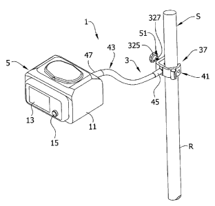
[0008] Fig. I is a perspective of a first embodiment of a clamping apparatus
mounting an enteral feeding pump to an IV pole;
[0009] Fig. 2 is a left side elevation of Fig. 1;
2c
CA 02545622 2010-03-11
[0010] Fig. 3 is a rear perspective of the clamping apparatus and medical
device
with the clamping apparatus exploded;
[0011] Fig. 4 is a side elevation of a flexible shaft of the clamping
apparatus;
[0012] Fig. 5 is an end view of the flexible shaft;
[0013] Fig. 6 is a section of the shaft taken in the plane including line 6-6
of Fig. 5;
2d
CA 02545622 2006-05-03
[0014] Fig. 6A is an enlarged detail of Fig. 6 showing a sleeve of the
flexible
shaft in a release position;
[0015] Fig. 6B is a longitudinal section of a first modified flexible shaft;
[0016] Fig. 6C is a longitudinal section of a second modified flexible shaft;
[0017] Fig. 7 is an enlarged perspective of a first version of a clamping
member of the clamping apparatus;
[0018] Fig. 8 is a horizontal section of the clamping member of Fig. 7;
[0019] Fig. 9 is an enlarged perspective of a second version of the clamping
member;
[0020] Fig. 10 is a longitudinal section of a flexible shaft of a clamping
apparatus of a second embodiment;
[0021] Fig. 11 is a perspective of a clamping member of the clamping
apparatus of the second embodiment;
[0022] Fig. 12 is a horizontal section of the clamping member of Fig. 11;
[0023] Fig. 13 is a fragmentary side elevation of a bed including a side rail
having the first embodiment of the clamping apparatus attached thereto;
[0024] Fig. 14 is a perspective of the clamping apparatus of the first
embodiment with the flexible shaft removed and a fragmentary portion of a
cylindrical pole received in the clamping member;
[0025] Fig. 14A is a cross-section taken along the plane including 14A-14A of
Fig. 14;
[0026] Fig. 15 is a perspective similar to Fig. 14 but with a fragmentary
portion of a planar table top received in the clamping member; and
[0027] Fig. 15A is a cross-section taken along the plane including 15A-15A of
Fig. 15.
[0028] Corresponding reference characters indicate corresponding parts
throughout the several views of the drawings.
Detailed Description of the Preferred Embodiments
[0029] Referring now to the drawings and in particular to Figs. 1 and 2, a
powered medical device assembly 1 includes a clamping apparatus 3 releasably
attached to a support member S to support a medical device 5 on the support
member
3
CA 02545622 2006-05-03
(the reference numerals designating their subjects generally). In the
embodiment of
Fig. 1, the support member S is a vertical IV pole (broadly, "a support
member)
having a cylindrical rod R extending up from a stand (not shown) that is
commonly
used to support medical paraphernalia such as IV bags (not shown) in a
hospital or
other healthcare environment. As discussed further below, the clamping
apparatus 3
is capable of mounting the medical device 5 on support members having other
than
cylindrical shapes. The clamping apparatus 3 is configured to allow full range
of
motion (i.e., six-degrees of freedom of motion) of the medical device 5
relative to the
support member S so the medical device can be positioned for better viewing
and
adjustment. The clamping apparatus 3 may be more broadly described as
"mounting
apparatus", as it will be understood that apparatus that mounts a medical
device
without clamping (e.g., including even a permanent attachment) falls within a
broader
scope of the present invention.
[00301 The medical device 5 may be any medical device used in diagnosing,
monitoring, or treating a patient. In the illustrated embodiment, the medical
device 5
is an enteral feeding pump used to regulate the delivery of nutritional fluids
to a
patient from a container (not shown) but it is understood that the medical
device could
be any other type of device that is typically mounted on a support. The pump 5
has a
housing 11 and a display screen 13 at the front of the housing for monitoring
the
operational status of the pump and a control knob 15 for making adjustments to
the
pump. As shown in Fig. 3, the pump 5 has a mounting stud 19 attached to the
back of
the housing 11 for releasable attachment to the clamping apparatus 3. The
mounting
stud 19 is cylindrical and has a radial external surface with recesses 23 and
a threaded
nipple 27 for mating with a threaded hole 29 on the housing 11. The pump 5 has
an
electrical cord 33 attached to the housing 11 for connection to an electrical
outlet (not
shown) to provide power to the pump. It is understood that the pump 5 may be
battery operated so that the cord 33 may be omitted from the pump without
departing
from the scope of this invention. It is envisioned that the pump 5 may also be
fluid
(e.g., air) powered.
[00311 The clamping apparatus 3 includes a clamp, generally indicated 37,
having a clamping member, generally indicated 41, for releasable attachment of
the
assembly 1 to the support member S and a securing rod 51 releasably attached
to the
4
CA 02545622 2006-05-03
clamping member for attaching the apparatus to the IV pole. The clamping
apparatus
3 includes a flexible shaft, generally indicated 43, attached to the clamping
member
41 at a first end 45 and releasably attached to the medical device 5 at a
second end 47.
The flexible shaft 43 is selectively configurable while connected to the pump
5 to
allow the pump to have complete freedom of motion relative to the support
member
S. The complete freedom of motion of the pump 5 relative to the support member
S
includes translation of the pump in any of the three dimensions (e.g., x, y,
and z-axis)
relative to the support as well as rotation or the ability to change the angle
of
orientation of the pump relative to any of the three axes so that the pump has
six
degrees of freedom of motion relative to the support. Moreover, once moved the
clamping apparatus 3 retains the medical device 5 in its new selected
position.
[00321 As shown in Figs. 4-6, the flexible shaft 43 has a generally tubular
body, generally indicated 61, with an internally threaded bushing 63 mounted
on the
body at the first end 45 of the shaft and a quick-release connector (locking
collar),
generally indicated 65, mounted on the body at the second end 47 of the shaft.
As
shown in Fig 6, the tubular body 61 includes a coil spring, generally
indicated 69,
having a plurality of coils 71 extending from the first end 45 to the second
end 47 of
the shaft 43. A stiffener 75 is disposed between the coils 71 to provide
stiffness to the
flexible shaft 43 and allow the shaft to be set in a stationary position when
bent. In
the illustrated embodiment, the stiffener 75 comprises a wire having a
triangular
cross-section but it is understood that the stiffener may have other shapes.
The
stiffener 75 is pliable to allow the spring 69 to bend and twist in any
direction but
provides sufficient resistance to prevent the spring from returning to its
original
position and shape. A sheath 77 covers the spring 69 and the stiffener 75 to
provide a
thin outer layer for the flexible shaft 43. The sheath 77 may be made from
plastic,
rubber, vinyl, or any other flexible material.
[00331 Referring now specifically to Fig. 6, the threaded bushing 63 mounted
on the first end 45 of the flexible shaft 43 has a threaded axial bore 81 at
its outer end
that opens to an axial cavity 85 at its inner end that receives the spring 69
and the
stiffener 75 of the flexible shaft 43. The threaded bushing 63 has a collar 87
surrounding the threaded bore 81 that forms an external surface 89 of the
flexible
shaft 43 that may be grasped for connecting the threaded bushing to the
clamping
CA 02545622 2006-05-03
member 41. As shown in Fig. 3, the outer axial surface of the bushing has a
rectangular notch 93 slightly greater in width than the diameter of the
threaded bore
81.
[0034] The quick release connector 65 is a "quick-disconnect" type connector
for releasable connection between the flexible shaft 43 and the mounting stud
19 on
the pump 5. As shown in Figs. 6 and 6A, the quick release connector 65
includes a
bushing 97 having an axially outer cavity 99 for receiving the mounting stud
19, an
axially inner cavity 101 for receiving the spring 69 and stiffener 75, and a
connector
actuating structure (sleeve) 103 slidable on the bushing. The bushing 97 has
radial
openings 107 that open to the outer cavity 99 of the bushing. Detent elements
111 are
housed in the openings 107 and protrude, at least in part, through the radial
openings
into the outer cavity 99. In the illustrated embodiment the connector 65 has
two
detent elements 111 in the form of metal balls spaced apart 180 degrees and
received
in respective radial openings 107 in the bushing. It is understood that the
quick
release connector 65 could have more or less than two detent elements 111, the
detent
elements may be other than spherical, and the detent elements may be radially
spaced
more or less than 180 degrees without departing from the scope of this
invention.
[0035] The sleeve 103 is slidable on the bushing 97 between an attach position
(Fig. 6) and a release position (Fig. 6A). A spring 115 mounted on the bushing
97
biases the sleeve 103 to the attach position. The sleeve 103 has a shoulder
119 that
contacts the balls 111 at the attach position to urge the balls radially
inward so that a
portion of the balls protrudes into the outer cavity 99 and to lock the balls
to prevent
radial movement of the balls away from the central axis of the bushing 97. The
sleeve
103 is positioned in the release position by sliding the sleeve on the bushing
97 in the
direction indicated by arrow Al (Fig. 6) toward the second end 47 of the
flexible shaft
43 to compress the spring 115. In the release position of Fig. 6A, the
shoulder 119 is
free from engagement with the balls 111 so that the balls may move radially
outward
away from the outer cavity 99 of the bushing 97.
[0036] It is understood that the flexible shaft 43 is releasably attached to
the
pump by holding the sleeve 103 of the quick-release connector 65 in the
release
position and placing the bushing 97 over the mounting stud 19 on the housing
so that
the external surface 21 of the mounting stud is received into the outer cavity
99 of the
6
CA 02545622 2006-05-03
bushing. The bushing 97 and flexible shaft 43 may be rotated as needed so that
the
balls 111 align with the locking recesses 23 on the outer surface 21 of the
mounting
stud 19. When the balls 111 are received in the recesses 23, the sleeve 103 is
released
so that the spring 115 urges the sleeve to the attach position and the
shoulder 119
engages the balls to bias the balls radially inward to form a secure locking
connection
between the flexible shaft 43 and the pump 5. The engagement of the balls 111
with
the locking recesses 23 on the mounting stud 19 provides an audible signal in
the
form of a "clicking" sound that provides confirmation that the pump 5 is
locked on the
flexible shaft 43. To release the pump 5 from the connector 65, the sleeve 103
is slid
to the release position and the mounting stud 19 may be disengaged from the
bushing
97 as the balls 111 are free to move radially outward from the outer cavity 99
so that
the balls can move out of the recesses 23 to remove the stud from the outer
cavity.
Thus, the sleeve 103 may be moved linearly and without rotation between the
attach
position and the release position of the quick-release connector 65 to allow
rapid
disengagement of the pump 5 from the flexible shaft 43. It will be understood
that
other types of connections for the pump 5 and flexible shaft 43 may be used
without
departing from the scope of the present invention.
[0037] As shown in Fig. 6B in a modified version of the flexible shaft,
generally indicated 125, the shaft may include a tube stiffener 129 made out
of rigid
material (e.g., copper, plastic, etc.) adjacent the second end 131 of the
flexible shaft.
The tube stiffener 129 replaces a portion of the spring 133 at the second end
131 of
the flexible shaft so that the flexible shaft is substantially rigid along the
axial length
of the tube stiffener and the portion and is flexible along the axial length
of the spring
133.
[0038] Fig. 6C shows another modified version of the flexible shaft, generally
indicated 139, including an internal stiffener 145 received through the middle
of the
coil spring 147. The internal stiffener 145 increases the stiffness of the
flexible shaft
139 but still allows the entire length of the flexible shaft to flex. The
internal stiffener
145 increases the amount of weight that can be supported in a stationary
position at
either end of the flexible shaft 139. It is understood that the tube stiffener
129 (Fig.
6B) and the internal stiffener 145 may range in axial length depending on the
specific
amount of rigidity or stiffness required in the flexible shaft 125, 139.
7
CA 02545622 2006-05-03
[0039] As shown in Figs. 7 and 8, the clamping member 41 is generally C-
shaped and has an inner surface, generally indicated 161, for contact with the
IV pole
or other support member S, an opening 163 for receiving the support member,
and an
outer surface generally indicated 165. As shown in the orientation of Fig. 8,
the
clamping member 41 has a lower portion 169 at the bottom of the clamping
member
generally perpendicular to a middle portion 171 so that the lower portion and
middle
portion meet at a bend 173 having an angle of approximately 90 degrees. A
lower
threaded hole 177 of the clamping member 41 passes through the lower portion
169
and a cylindrical, non-threaded opening 179 passes through the middle portion
171.
The middle portion 171 has a rectangular shoulder 183 protruding from the
outer
surface 165 of the clamping member 41. The shoulder 183 is sized to be
received in
the rectangular notch 93 (Fig. 3) on the threaded bushing 63 at the first end
45 of the
flexible shaft 43 when the flexible shaft is connected to the clamping member
41.
[0040] A first upper portion 187 of the clamping member 41 is upwardly bent
relative to the middle portion 171 so that the middle portion and the first
upper
portion meet at a bend 189 having an angle greater than 90 degrees. A second
upper
portion 193 is downwardly bent relative to the first upper portion 187 so that
the first
and second upper portions meet at an upper bend 195 in the clamping member 41.
An
upper threaded hole 199 is located on the upper bend 195 between the first and
second
upper portions 187, 193 so that the upper hole is axially aligned with the
lower hole
177 in the lower portion 169 of the clamping member 41.
[0041] As shown in Fig. 7 and 8, the first upper portion 187 has two roughly
semi-cylindrical protrusions 205, 207 on its outer surface that form a
cylindrical
recess 211 in the first upper portion. The cylindrical recess 211 provides a
storage
area for an AC power adapter cord (not shown) when the cord is not in use. The
two
protrusions 205, 207 are separated by an axial slot 213 that allows the power
adapter
cord or other cord of the pump 5 to be received in the recess 211.
[0042] Fig. 9 shows another version of the clamping member 217 that is
substantially similar to the embodiment of Fig. 7 but the middle portion 219
of the
clamping member has a bracket, generally indicated 223, on its outer surface
225 for
storing an electrical cord 33 (Fig. 3) or other cable of the pump 5. In the
embodiment
of Fig. 9, the bracket 223 includes two L-shaped fingers generally indicated
227, 229
8
CA 02545622 2006-05-03
protruding from the outer surface 225 of the middle portion 219 of the
clamping
member 217 that are spaced apart in an opposed (back-to-back) orientation.
Each
finger 227, 229 has a respective first portion 235, 237 and respective second
portion
239, 241 joined by a 90 degree bend 243, 245. The second portion 239, 241 of a
respective finger 227, 229 retains the electrical cord 33 (Fig. 3) on the
first portion
235 when the cord is wrapped around the bracket 223.
[00431 The second upper portion 247 of the clamping member 217 of Fig. 9
has a tab 249 adjacent the cylindrical recess 251 and protruding from the
outer surface
225 of the clamping member. The tab 249 provides for direct attachment of the
clamping member 217 to the housing 11 of the pump 5 (i.e., omitting flexible
shaft
43, 125, 139). The tab 249 has a cylindrical hole 253 for receiving a threaded
fastener
(not shown) that attaches the clamping member 217 directly to the pump housing
11.
In the illustrated embodiment the cord bracket 223 and tab 249 are integrally
formed
with the C-shaped clamping member 217 but it is understood that the bracket
and/or
tab could be separate parts that may be attached to the clamping member by
welding
or other attachment methods.
[00441 As shown in Fig. 3, the flexible shaft 43 is attached to the clamping
member 41 by a threaded bolt 261 or other fastener that is received through
the
opening 179 in the middle portion 171 of the clamping member and is in
threaded
engagement with the threaded bushing 63 on the first end 45 of the flexible
shaft.
When the axially outer surface of the threaded bushing 63 on the flexible
shaft 43
abuts the outer surface 165 of the middle portion 171 of the clamping member
41, the
shoulder 183 on the middle portion of the clamping member is received in the
notch
93 on the threaded bushing to align the shaft with the clamping member. Also,
the
engagement of the notch 93 on the threaded bushing 63 and the shoulder 183 on
the
clamping member 41 prevents the bushing from rotating when the threaded
fastener
261 is threadably advanced into the bushing. The threaded connection between
the
flexible shaft 43 and the clamping member 41 allows the flexible shaft and the
clamping member to be disassembled and interchanged with other parts (e.g., a
flexible shaft having a longer or shorter length, a flexible shaft having an
increased or
decreased stiffness, or a clamping member having a different shape) by
removing the
threaded fastener 261. It is understood that the flexible shaft 43 may be
connected to
9
CA 02545622 2006-05-03
the clamping member 41 with other attachment mechanisms (e.g., quick-
disconnect
connector, rivet, etc.) without departing from the scope of this invention.
[0045] Figs. 10-12 show components of a clamping apparatus of a second
embodiment having an alternative connection between the clamping member 273
and
the first end 275 of the flexible shaft 279. As shown in Fig. 10, the flexible
shaft 279
of this embodiment has a threaded bushing 283 at its first end 275 with a hex
head
fitting 285 having six radial flats 287 (only two of which are shown in Fig.
10) at the
radially outer surface of the threaded bushing. The bushing 283 has a threaded
bore
291 for receiving the threaded fastener (not shown, but the same as the
fastener shown
in Fig. 3) and a flat outer axial surface 293 at the first end 275 of the
flexible shaft
279.
[0046] Figs. 11-12 show the clamping member 273 having a middle portion
299 for mating with the flat outer axial surface 293 of the threaded bushing
283 of
Fig. 10. The outer surface 301 of the middle portion 299 of the clamping
member 273
has two spaced apart shoulders 305, 307 and a substantially flat contact
surface 311
between the shoulders. The cylindrical opening 315 in the middle portion 299
of the
clamping member 273 is centrally located opening from the inner surface 317 of
the
clamping member to the flat contact surface 311 on the outer surface 301 of
the
clamping member.
[0047] In this embodiment, the flexible shaft 279 is connected to the clamping
member 273 by axially aligning the threaded bore 291 of the bushing 283 with
the
cylindrical opening 315 in the middle portion 299 of the clamping member. The
flat
outer axial surface 293 of the threaded bushing 283 abuts against the flat
contact
surface 311 of the clamping member 273 so that the threaded fastener 261 (Fig.
3)
passes through the cylindrical opening 315 and connects the flexible shaft 279
and the
clamping member. The distance between the shoulders 305, 307 on the outer
surface
301 of the middle portion 299 is such that opposed radial flats 287 of the hex
head
fitting of the threaded bushing 283 fit between the shoulders so that the
bushing is
prevented from rotating when the threaded fastener 261 is advanced into the
threaded
bore 291. The engagement of the shoulders 305, 307 with a respective radial
flat 287
of the hex head fitting 285 of the threaded bushing 283 allow the threaded
fastener
261 to be advanced in the threaded bore 291 of the bushing without the use of
a
CA 02545622 2006-05-03
wrench or other tool to hold the threaded bushing in a stationary position
during
connection of the flexible shaft 279 to the clamping member 273.
[00481 The clamping member 41 attaches to the support member S by
positioning the clamping member such that the support member is received
through
the opening 163 and contacts the inner surface 161 of the clamping member. The
securing rod 51 has a knob 325 and a threaded stem 327 that threadably engages
one
of the upper and lower threaded holes 199, 177 of the clamping member 41 and
contacts the support member S to secure the clamping member to the support
member. The clamping member 41 of the present invention is shaped to receive
support members S of various shapes so that the pump 5 may be mounted in a
variety
of locations. For example, the clamping apparatus 3 may be mounted on a pole
such
as a vertical N stand S (Figs. 1 and 2) or a horizontal bed rail pole BR (Fig.
13). As
shown in detail in Figs. 14 and 14A, the securing rod 51 is threadably
inserted
through the lower threaded hole 177 in the clamping member 41 so that the end
of the
securing rod contacts the outer surface of the pole S. The surface of the pole
S
opposite the securing rod 51 is positioned in contact with the first and
second upper
portions 187, 193 of the clamping member 41. The clamping apparatus 3 and the
medical device assembly 1 are secured to the support member S by tightening
the
securing rod 51 so that the pole is in secure engagement with the clamping
member
41.
[00491 As shown in Figs. 15 and 15A, the clamping apparatus 3 may be
configured for clamping the medical device 5 to a table top or other planar
support
member PS. In this arrangement, the securing rod 51 is threadably received
through
the upper threaded hole 199 of the clamping member 41 to contact the upper
surface
US of the table top PS. The lower surface LS of the table top PS contacts the
inner
surface 161 of the lower portion 169 of the clamping member 41 so that the
table PS
is held in clamped engagement between the securing rod 51 and the clamping
member. The clamping apparatus 3 is secured to the table PS by turning the
knob 325
on the securing rod 51 so that the rod engages the upper surface US of the
table and
urges the lower surface LS of the table into secure contact with the inner
surface 161
of the clamping member 41.
11
CA 02545622 2006-05-03
[00501 It is understood that the clamping member 41 of the present invention
allows the pump 5 to be mounted on either a cylindrical surface S (Fig. 14) or
a planar
surface PS (Fig. 15). Thus the pump 5 may be conveniently mounted in a
healthcare
environment on an IV pole, horizontal or vertical bed rail, wheelchair tubing,
or other
support typical of a hospital or other medical facility. In addition, the pump
5 may be
mounted on a table top PS or other structure for use in a home or other
setting outside
of a medical facility. Other suitable support structures for mounting the pump
5
include, but are not limited to, powered medical scooters or mobility chairs,
multi-
parameter carts, doors, tables, cabinets, bed stands, countertops, chairs,
medical trays,
television trays, and desks. Further, the clamping member 41 may receive a
pole S
having a first thickness Ti (Fig. 14A) or a table top PS having a generally
planar
surface with a thickness T2 (Fig. 15B) that may be greater than or less than
the
thickness of the pole.
[0051] The flexible shaft 43 of the present invention allows six degrees of
freedom of motion of the pump 5 relative to the support member S. The pump 5
may
be mounted in a first position (Fig. 1 and 2) in which the pump is retained by
the
flexible shaft 43 in a stationary position so that a point on the housing 11
(e.g., the
front of the housing) is a first distance D1 away from the support. By
applying a
force to the housing 11 of the pump 5, the flexible shaft 43 may be
manipulated so
that the pump is moved to a second position (shown in phantom in Fig. 2) in
which
the pump is retained by the flexible shaft in a stationary position so that
the point on
the housing is a second distance D2 greater than the first distance D 1 from
the support
member S. It is understood that the pump 5 may be positioned closer to the
pole S at
the second position such that the distance D2 is less than the first distance
D 1. Also,
the pump 5 may be tilted up or down about a horizontal axis (e.g., x-axis
Figs. I and
2) perpendicular to the support S and passing through the pump to allow better
viewing of the display screen 13 on the pump. Further, the pump 5 may be
tilted left
or right about a vertical axis (e.g., y-axis Figs. 1 and 2) to allow the
display screen 13
to be viewed or the controls 15 to be accessed. The pump 5 may be twisted
(i.e.,
rotated) about the horizontal axis A2 that may intersect the support S and the
pump so
that the screen 13 may be orientated for better viewing. It is understood that
the pump
may be positioned such that the horizontal axis A2 does not intersect the
support S
12
CA 02545622 2006-05-03
without departing from the scope of this invention. The flexible shaft 43 also
allows
the pump 5 to be moved anywhere along a line intersecting the support S and
the
pump so that the only factor limiting the position of the pump relative to the
support is
the length of the flexible arm.
[00521 When introducing elements of the present invention or the preferred
embodiment(s) thereof, the articles "a", "an", "the" and "said" are intended
to mean
that there are one or more of the elements. The terms "comprising",
"including" and
"having" are intended to be inclusive and mean that there may be additional
elements
other than the listed elements.
[00531 In view of the above, it will be seen that the several objects of the
invention are achieved and other advantageous results attained.
[00541 As various changes could be made in the above constructions without
departing from the scope of the invention, it is intended that all matter
contained in
the above description or shown in the accompanying drawings shall be
interpreted as
illustrative and not in a limiting sense. Further, all dimensional information
set forth
herein is exemplary only and is not intended to limit the scope of the
invention. It is
understood that any of the particular embodiments of the present invention may
include one or more of the aspects or features of the invention as described
herein and
illustrated in the drawings.
13