Note: Descriptions are shown in the official language in which they were submitted.
CA 02545799 2011-05-03
ELECTRICAL CEILING BOX FOR FIXTURE SUPPORT
Field of the Invention
[0001] The present invention is directed to an electrical box and to
an electrical box assembly for supporting an electrical fixture. More
particularly, the invention is directed to an electrical box having
mounting holes within the perimeter of the box for supporting an
electrical fixture such as a ceiling fan or light fixture.
Background of the Invention
[0002] Electrical boxes are used to mount electrical fixtures such as
ceiling fans and light fixtures. The electrical boxes commonly have
tabs or flanges connected to a side wall that extend into the center of
the box. The tabs include holes for receiving screws for fastening the
electrical fixture to the box and, for supporting the electrical fixture.
The electrical box also encloses the wires and the electrical
connections between the power supply and the electrical fixture. Care
CA 02545799 2006-05-04
= -2-
must be taken when mounting the electrical fixture to the electrical
box to prevent the mounting screws from contacting and damaging
the electrical wires within the box. Examples of electrical boxes that
have inwardly extending mounting tabs are disclosed in U. S. Patent
No. 5,988,421 and U.S. Patent No. 5,883,331.
[0003] Other electrical boxes are also known that include mounting
holes for mounting the electrical box to a support. The mounting
holes can be provided in the bottom wall. In other electrical boxes,
the side wall is formed with a block that has a hole extending
completely through the block to receive the mounting screw.
Examples of such electrical boxes are disclosed in U.S. Patent No.
6,646,201; U.S. Patent No. 6,207,898 and U.S. Patent No. 6,335,486.
[0004] Many different types of electrical boxes are known in the art
for use as ceiling boxes. Most of the prior ceiling boxes were designed
either specifically for supporting ceiling fans or specifically for
supporting light fixtures. The electrical boxes that are typically used
for ceiling fan support are different than those used for supporting
light fixtures. In particular, electrical boxes for supporting ceiling fans
typically use standard 10-32 screws, while electrical boxes for light
fixture support use standard 8-32 screws. Moreover, Underwriters
Laboratories (UL) has a test that electrical ceiling boxes must pass in
order to be used as the sole support of a ceiling fan. Typically, a
conventional electri cal box used for supporting a light fixture or the
like can not be used for supporting a ceiling fan.
[0005] Accordingly, when an electrical box is installed in a ceiling,
the installer must determine whether a ceiling fan or a light fixture
will be attached to the electrical box so that the correct type of
electrical box is installed. If a light fixture type electrical box is
initially installed at a particular location and then subsequently it is
CA 02545799 2006-05-04
-3-
decided that a ceiling fan should be installed at that location, the
original electrical box must typically either be modified or replaced
with an electrical box which is approved for ceiling fan support.
Adapting existing light fixture boxes for use with ceiling fans is often
quite difficult since light fixture boxes use smaller fasteners and are
generally not strong enough to support fans without substantial
reinforcements or special brackets.
[0006] An electrical box that is approved for ceiling fan support can
also be used to support an electrical device such as a light fixture.
The National Electrical Code permits lighting fixtures to be supported
by electrical boxes proved for ceiling fan support but not vice-a-versa.
[0007] Adapting existing ceiling fan boxes for use with a light fixture
or the like is not always easily accomplished, since fasteners for the
light fixture are different from the fasteners use with ceiling fans. For
example, fasteners used with light fixtures generally smaller in
diameter than fasteners used with ceiling fans. Moreover, fixture
support fasteners often come in various colors, finishes and lengths as
well as with various decorative features which may be difficult, if not
impossible to match, in a fastener which can be used with an
electrical box approved for use with ceiling fans. A National Electrical
Code provision (N.E.C. 370-27 (c)) has been proposed which would
require that electrical boxes approved for use with ceiling fans to be
installed at most locations in a building, such as in stairways, foyers
and bathrooms.
[0008] Examples of prior art ceiling fan supports are disclosed in
the following U.S. Patent No. 4,391,428 to Grimes; U.S. Patent No.
4,880,128 to Jorgensen; U.S. Patent No. 4,892,211 to Jorgensen; U.S.
Patent No. 5,234,119 to Jorgensen et al.; and U.S. Patent No.
5,407,088 to Jorgensen et al.
CA 02545799 2006-05-04
-4-
[0009] Examples of prior art electrical boxes are disclosed in the
following U.S. Patent No. 4,315,100 to Hasibeck et al.; U.S. Patent No.
4,580,689 to Slater; U.S. Patent No. 4,874,905 to Schnell et al.; U.S.
Patent No. 4,954,667 to Jorgensen et al.; and U.S. Patent No.
5,135,411 to Wiley et al. These electrical boxes generally have
mounting tabs that extend inwardly with screw holes that overlie the
internal cavity of the box.
[0010] In view of the above noted problems, there exists a need for
an electrical box approved for use with ceiling fans that can
accommodate both standard light fixture fasteners as well as ceiling
fan fasteners and that can receive mounting screws without
interfering with the electrical box. This invention addresses this need
as well as other needs and problems which will become apparent
those skilled in the art from this disclosure.
Summary of the Invention
[0011] The present invention is directed to an electrical box and to
an electrical box assembly for supporting an electrical fixture. The
invention is particularly directed to an electrical box having mounting
holes in the perimeter for mounting an electrical fixture to the box.
The mounting holes are positioned so that mounting screws are
outside the wall of the electrical box.
[0012] Accordingly, one aspect of the invention is to provide an
electrical box that is formed as a one piece unitary structure. The one
piece electrical box can be formed from a single sheet of metal or other
material that is stamped into the desired shape. Alternatively, the
electrical box can be molded from a plastic resin material.
[0013] Another aspect of the invention is to provide an electrical box
with an outwardly extending mounting flange where the box is capable
CA 02545799 2006-05-04
of selectively supporting a ceiling fan or a lighting fixture. The
mounting flange has a first aperture for receiving a coupling member
such as a screw that is capable of supporting a ceiling fan. A second
aperture is provided in the mounting flange for receiving a coupling
member for mounting a lighting fixture to the box.
[0014] In one embodiment, the electrical box includes a raised
portion in a bottom wall and having an aperture for receiving a
grounding screw. The raised portion in the bottom wall is spaced from
the bottom wall a distance greater than the length of the grounding
screw so that the ground screw is received within the cavity formed by
the raised portion. The raised portion is also spaced from the bottom
wall a distance less than the height of the side wall. In one
embodiment, the raised portion forms a ground screw receiving flange
that is formed in the side wall of the electrical box.
[0015] Another aspect of the invention is to provide an electrical box
having a side wall with a non-linear shaped recess and a mounting
flange extending outwardly from the side wall and overlying the
recess.
[0016] The various features of the invention are basically attained
by providing an electrical ceiling box for supporting an electrical
device. The box comprises a bottom wall with a substantially circular
side wall coupled to the bottom wall which has a concave inner
surface, a convex outer surface, and at least one recessed portion.
The recessed portion has a concave outer surface connected to the
convex surface of the side wall and a convex inner surface connected
to the concave inner surface of the side wall.
[0017] The aspects of the invention are also attained by providing a
universal electrical ceiling box adapted to support an electrical device
which comprises a bottom portion having a plurality of mounting
CA 02545799 2006-05-04
-6-
holes adapted for receiving fasteners for mounting the box to a
support surface. The bottom portion has an outer edge which defines
an outer dimension of the box. A side wall extends from the outer
edge in a direction substantially perpendicular to the bottom portion
defining an internal cavity. The side wall has an outer surface with a
first concave recessed portion which extends in an inward direction
with respect to the box. A first flange extends from an upper end of
the side wall substantially parallel to the bottom portion and overlies
the concave recessed portion in the side wall. The first flange has a
plurality of holes which extend therethrough and are adapted for
receiving a fastener for coupling the electrical device to the box. The
holes in the first flange are aligned with the concave recessed portion
and are positioned outwardly with respect to the side wall.
[0018] The aspects of the invention are further attained by providing
an electrical ceiling box adapted to support an electrical device, which
comprises a bottom wall having a peripheral edge and a plurality of
mounting holes extending therethrough for receiving a fastener for
coupling the box to a support surface. A side wall extends in a
substantially perpendicular direction from the peripheral edge of the
bottom wall. A first flange extends from the side wall in a radially
outward direction. The first flange has a non-linear inner edge
coupled to the side wall and an outer radial edge aligned with the
peripheral edge of the bottom wall. A plurality of holes extend
through the first flange and are adapted for receiving a fastener for
coupling the electrical device to the box. A second flange extends from
the side wall in a radially outward direction. The second flange has a
non-linear inner edge coupled to the side wall and an outer radial
edge aligned with the peripheral edge of the bottom wall. A plurality of
holes extend through the second flange and are adapted for receiving
CA 02545799 2006-05-04
-7-
a fastener for coupling the electrical device to the box. The holes in
the first flange and the second flange are oriented outwardly from the
side wall.
[0019] The aspects of the invention are still further attained by
providing an electrical ceiling box adapted to support an electrical
device, with the box comprising a bottom wall having an outer edge
and a plurality of mounting holes for receiving a fastener for mounting
the box to a support. A substantially continuous side wall extends
from the outer edge of the bottom wall in a direction substantially
perpendicular to the bottom wall and defining an internal cavity. The
bottom wall and the side wall have a substantially circular shape. The
side wall has a first convex arcuate section with a first end and a
second end. A second convex arcuate section has a first end and
second end. A first concave arcuate section extends between the first
end of the first convex arcuate section and the first end of the second
convex arcuate section. A second concave arcuate section extends
between the second end of the first convex arcuate section and the
second end of the second convex arcuate section. A first flange
extends outwardly from an upper end of the side wall at the first
concave arcuate section and coextensive with a first recessed area
defined by the first concave arcuate section. A second flange extends
outwardly from an upper end of the side wall at the second concave
arcuate section and is coextensive with a second recessed area defined
by the second concave arcuate section.
[0020] The aspects of the invention are yet further attained by
providing an electrical ceiling box adapted to support an electrical
device. The box comprises a bottom wall with an outer edge which
has a plurality of mounting holes extending therethrough for receiving
a fastener for coupling the box to a support. The bottom wall has a
CA 02545799 2006-05-04
-8-
substantially circular shape with a first convex arcuate portion and a
second convex arcuate portion. The first and second convex arcuate
portions have a first radius. The bottom wall has a first concave
arcuate portion which extends between a first end of the first convex
arcuate portion and a first end of the second convex arcuate portion.
A second concave arcuate portion extends between a second end of
the first arcuate portion and a second end of the second arcuate
portion. The first and second concave arcuate portions have a second
radius less than the first radius. A side wall extends from the outer
edge of the bottom wall in a direction substantially perpendicular to
the bottom wall. The side wall terminates at an upper end. A first
flange portion extends from the upper end of the side wall and overlies
the first concave arcuate portion. The first flange has a plurality of
mounting holes for receiving a fastener for coupling the electrical
device to the box. A second flange portion extends from the upper end
of the side wall and overlies the second concave arcuate portion. The
second flange has a plurality of mounting holes for receiving a
fastener for coupling the electrical device to the box.
[0021] The aspects of the invention are still further attained by
providing an electrical box for supporting an electrical device which
comprises a substantially planar bottom wall having an outer edge
and a continuous side wall having a bottom edge connected to the
outer edge of the bottom wall and extending in a direction
substantially perpendicular to the bottom wall and terminating at a
top edge. The side wall forms a substantially circular shape. A recess
in the side wall forms a flange having a hole for receiving a ground
screw. The flange is integral with the side wall and spaced between
the top edge and bottom edge of the side wall.
CA 02545799 2011-05-03
-9-
[0022] Other aspects, advantages and salient features of the
invention will become apparent from the following detailed description
of the invention, which taken in conjunction with the annexed
drawings disclose preferred embodiments of the invention.
Brief Description of the Drawings
[0023] The following is a brief description of the drawings in which:
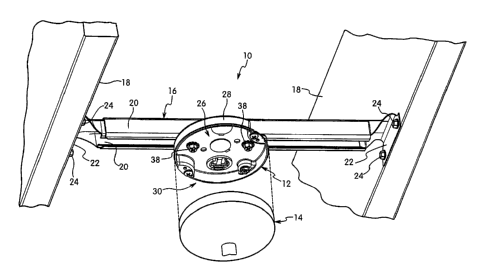
[0024] Figure 1 is a perspective view of the electrical box assembly
in a first embodiment showing a ceiling fan mounted to the electrical
box;
[0025] Figure 2 is a perspective view of the electrical box of Figure 1
showing a cover member on the electrical box;
[0026] Figure 3 is a top plan view of the electrical box of Figure 1;
[0027] Figure 4 is a partial cross-sectional view of the flange taken
along line 4-4 of Figure 3;
[0028] Figure 5 is a partial cross-sectional view of the flange and
ground screw taken along line 5-5 of Figure 3;
[0029] Figure 6 is a bottom perspective view of the electrical box of
Figure 1;
[0030] Figure 7 is a top perspective view of the electrical box in
another embodiment; and
[0031] Figure 8 is a bottom perspective view of the electrical box of
Figure 7.
Detailed Description of the Invention
[0032] The present invention is directed to an electrical box and an
electrical box assembly for supporting an electrical fixture. The
invention is particularly directed to an electrical box having a plurality
of mounting holes within the perimeter of the electrical box for
i 4,. =r~i ira,rrlMlm.... 1 w ~I. ,u nr~.nxnsi...,p.r-.
CA 02545799 2006-05-04
_10-
receiving fasteners for coupling an electrical fixture to the electrical
box. The electrical box typically includes knock-out plugs and
mounting holes.
[0033] Referring to Figures 1-6, a first embodiment of the electrical
assembly 10 is shown. Electrical assembly 10 includes an electrical
box 12 for supporting an electrical fixture 14. Electrical fixture 14 is
typically a ceiling fan or a light fixture. Electrical box 12 is mounted
to a suitable support which can be a ceiling joist or other solid
surface. In the embodiment illustrated, electrical box 12 is coupled to
a support bracket 16 extending between a pair of ceiling joists 18.
Bracket 16 as shown includes a pair of telescoping arms 20 to
accommodate variations in the spacing between joists 18. Arms 20
include a mounting flange 22 at one end having apertures for
receiving fasteners 24 to secure mounting bracket 16 to joists 18.
Typically, fasteners 24 are screws or bolts that extend into joists 18 to
enable mounting bracket 16 and electrical box 12 to support the
intended weight.
[0034] Referring to Figure 2, electrical box 12 includes a bottom
portion 26 defining a bottom wall and a side portion 28 defining a side
wall to form an open end 30. Bottom portion 26 and side portion 28
define an internal cavity 32 of electrical box 12 for containing wires,
electrical connections or other electrical components. It will be
understood that the reference to bottom portion 26 as shown in Figure
2 refers to the bottom end of cavity 32 regardless of the orientation of
electrical box 12 when installed for use. For example, electrical box
12 as shown in Figure 1 is mounted in the ceiling of a structure so
that open end 30 faces in a downward direction and bottom portion
26 is oriented at an upper end of electrical box assembly 12.
CA 02545799 2006-05-04
-11-
[0035] Bottom portion 26 of electrical box 12 in the embodiment
illustrated has a substantially flat planar surface with a plurality of
apertures 34 and a plurality of knock-out or pry-out plugs 36.
Apertures 34 are positioned to enable electrical box 12 to be attached
to the intended support. As shown in Figure 2, apertures 34 are
positioned to receive a fastener for connecting electrical box 12 to
mounting bracket 16. Preferably, apertures 34 have a dimension to
allow fasteners 38 to pass completely through so that the fasteners
can connect with the support surface. Knock-outs 36 are formed by
stamping or punching a partial circular cut through bottom portion
26. Knock-outs 36 are formed with a tab 40 to connect knock-outs 36
with bottom portion 26. In the embodiment illustrated, three knock-
outs 36 are provided in bottom portion 26 in locations to supply the
electrical wiring to the cavity 32 of electrical box 12. One or more of
knock-outs 36 are removed by bending tab 40 until broken. Typically,
an electric cable connector 42 is fitted into the opening after the
knock-out is removed for feeding electrical wires into electrical box 12
in a conventional manner. The electrical cable connector can be a
conduit fitting, a connector for armored cable or a connector for non-
metallic cables.
[0036] Electrical box 12 in the illustrated embodiment has a
substantially circular shape formed by bottom portion 26 and side
portion 28. Bottom portion 26 has a top surface 44 and a bottom
surface 46. Bottom portion 26 has a substantially circular shaped
outer edge 48. Side portion 26 is coupled to outer edge 48 of bottom
portion 26 and extends away from top surface 44 in a direction
substantially perpendicular to the plane of bottom portion 26. Side
portion 26 has an upper edge 50 having a lip 52 for mating with an
electrical fixture. Side portion 26 has a height so that cavity 32 has a
r.. .... 4....~. ...in.n.IMxi.,..., 4--4-xm-4... i...
CA 02545799 2006-05-04
-12-
volume sufficient to contain electrical wiring and connectors for
connecting a power supply to an electrical fixture.
[0037] Side portion 28 has at least one and preferably two recessed
portions 54 that form a concave cavity extending inwardly from side
portion 28 toward the center of electrical box 12. A mounting flange
56 is formed along the upper edge 58 of recessed portions 54.
Mounting flange 56 has an inner edge contiguous with the upper edge
58 of side portion 28 in the recessed portions 54 and is coextensive
with recessed portion 54. Mounting flange 56 has an outer edge 60
aligned with side portion 28 so that electrical box 12 has a
substantially circular shape with a substantially uniform radius. As
shown in Figure 2, mounting flange 56 is positioned inside the radius
of electrical box 12 and side portion 28.
[0038] Side portion 28 has a first arcuate section 62 having a
convex outer surface 64 and a concave inner surface 66. Side portion
28 has a second arcuate shaped section 68 having a convex outer
surface 70 and a concave inner surface 72. As shown, first arcuate
section 62 is diametrically opposed to second arcuate section 68. In
the embodiment illustrated, two recessed portions 54 extend between
the respective first and second ends of first arcuate section 62 and
second arcuate section 68. Recessed portions 54 are preferably non-
linear and have a generally continuous curved shape extending
between the respective ends of the first arcuate section 62 and second
arcuate section 68 of side portion 28. In one embodiment, recessed
portions 54 in the embodiment shown have a semi-circular shape
forming an outwardly facing concave surface 74 and an inwardly
facing convex surface 76. As shown in Figure 3, recessed portions 54
have a radius less than the radius of side portion 28.
CA 02545799 2006-05-04
-13-
[0039] Mounting flanges 56 are preferably substantially planar and
extend substantially perpendicular to side portion 28 and recessed
portions 54. Mounting flanges 56 are coplanar with each other and
substantially parallel to bottom portion 26 and define a top surface of
electrical box 12. Each mounting flange 56 has a pair of spaced-apart
mounting holes of different sizes to accommodate different electrical
fixtures. Each mounting flange 56 has a first mounting hole 78
formed therein with internal threads for threadedly receiving a screw
80. As shown in Figure 4, a collar 82 extends from the bottom side of
mounting flange 56 surrounding first mounting hole 78. Collar 82
has an axial length less than the height of side portion 28 and has an
axial length sufficient to engage the threads of screw 80 to support the
weight of the electrical fixture. Collar 82 can be formed by punching
or stamping hole 78 or by attaching a separate member to flange 56.
Electrical box 12 can include a cover 84 that can be attached to
electrical box 12 by screws 80 when an electrical fixture is not
mounted to box 12. As shown in Figure 4, screws 80 have an axial
length such that when seated in first mounting hole 78, are spaced a
slight distance from bottom portion 26. In this manner, electrical box
12 can be mounted on the flat surface and screws 80 can be threaded
into first mounting hole 78 without bottoming out against the support
surface. In preferred embodiments, first mounting hole 78 has a
threaded internal surface that has a dimension for receiving a 10-32
screw sufficient for mounting and supporting the weight of a ceiling
fan.
[0040] Each mounting flange 56 includes a second mounting hole
86 that has a diameter slightly less than the diameter of first
mounting hole 78. Preferably, second mounting hole 86 has a
threaded internal bore for threadedly receiving an 8-32 screw for
-.:... .. _. F =.+I=.. =..nMee: wJF-rWed.xlln+ M .F=..
CA 02545799 2006-05-04
-14-
mounting a lighting fixture or other electrical device to electrical box
12. Each mounting hole 78 and 86 extend completely through
mounting flange 56 and have a center axis substantially
perpendicular to the plane of mounting flanges 56. In one
embodiment, second mounting hole 86 can have a collar on the
bottom surface of mounting flange 56 for securely receiving mounting
screws.
[0041] Referring to Figures 1 and 2, electrical box 12 includes a
ground wire mounting flange 88 having a threaded aperture 90 for
receiving a ground wire screw 92. Screw 92 is threaded into aperture
90 to connect a ground wire 94 to electrical box 12 as shown in Figure
5. Flange 88 is formed by a concave recessed portion 96 in side
portion 28. In one embodiment, recessed portion 96 has an axial
height less than an axial height of side portion 28. Recessed portion
96 is formed by an arcuate shaped section 98 extending substantially
perpendicular to bottom portion 26 and has a concave outer surface
100 and a convex inner surface 102. In one embodiment, flange 88 is
positioned at about a mid-point along the axial height of side portion
28. Screw 92 has an axial length less than the height of arcuate
section 98 so that screw 92 is completely received within recessed
portion 96. In this manner, electrical box 12 can be mounted against
a flat surface and screw 92 can be threaded through aperture 90 to
couple ground wire 94 to electrical box 12 without interference from
the support surface. Ground screw mounting flange 88 is integrally
formed with the side portion 28 and bottom portion 26. It is desirable
to position flange 88 close to the top edge of side portion 28 while
providing a sufficient space to allow the head of ground screw 92 and
ground wire 94 to sit below the top edge of side portion 28.
CA 02545799 2006-05-04
r - 15 -
[0042] Electrical box 12 can be made of any suitable material such
as plastic or metal. Preferably, bottom portion 26 and side portion 28
has a substantially uniform thickness and is formed as a one-piece
unitary member. In one embodiment, electrical box 12 is formed from
a single sheet of metal that is stamped or pressed into the desired
shape so that each portion has a substantially uniform thickness.
[0043] In the embodiment illustrated, electrical box 12 has a
substantially circular shape defined by first arcuate section 62 and
second arcuate section 68 of side portion 28. First arcuate section 62
and second arcuate section 68 of side portion 28 and the arcuate
sections of recessed portions 54 form a continuous side wall of
electrical box 12 to contain electrical wiring and connectors. Recessed
portions 54 extend inwardly so that mounting flanges 56 are spaced
outwardly from the side wall and inwardly from the perimeter of
electrical box 12. As shown in Figure 2, mounting holes 78 and 86 in
mounting flanges 56 are spaced inwardly from the outer perimeter of
electrical box 12 and separated from the internal cavity 32 of electrical
box 12 by the arcuate section of recessed portions 54. Aperture 90 in
flange 88 is also spaced inwardly from the outer perimeter of electrical
box 12 and separated from cavity 32 by arcuate section 98 to prevent
interference of screw 92 with electrical wiring, connectors or other
components within cavity 32.
[0044] Referring to Figures 7 and 8, a second embodiment of the
invention is illustrated. As in the first embodiment, an electrical box
110 is provided having a substantially circular shape formed by a
bottom wall 112 and a side wall 114. Bottom wall 112 has a
substantially planar surface with a side edge 116. A plurality of
mounting holes 118 are provided in bottom wall 112 for receiving a
fastener such as a screw for mounting electrical box 110 to a support
CA 02545799 2006-05-04
-16-
surface. A plurality of pry-out or knock-outs 120 are provided for
supplying electrical wiring to an inner cavity 122 of electrical box 110.
Side wall 114 is continuous and has a substantially circular shape.
[0045] As in the previous embodiment, side wall 114 has a first
recessed portion 124 having a continuous first curved section 126.
First curved section 126 has a concave outer surface 128 and a
convex inner surface 130. Side wall 114 further has a second
recessed portion 132 formed by a second curved section 134. Second
curved section 134 has a concave outer surface 136 and a convex
inner . surface 138. In, one embodiment, first curved section 126 and
second curved section 134 have a semi-circular shape.
[0046] As shown in Figure 7, side wall 114 is formed by a first
arcuate section 140 having a concave inner surface 142 and a convex
outer surface 144. Side wall 114 further has a second arcuate section
146 having a concave inner surface 148 and a convex outer surface
150 as shown in Figure 8. First curved section 126 of first recess 124
extends between a first end 152 of first arcuate section 140 and a first
end 154 of arcuate section 146. Curved section 134 of second
recessed portion 132 extends between a second end 156 of arcuate
section 140 and a second end 158 of arcuate section 146. In this
manner, first and second arcuate sections 140 and 146 and curved
sections 126 and 134 form a continuous wall of electrical box 110.
[0047] Curved section 126 of first recess portion 124 has a height
substantially equal to the height of first arcuate section 140 and
second arcuate section 146 of side wall 114 and terminates at an
upper edge. In the embodiment illustrated, curved section 126 has a
substantially semi-circular shape with a radius less than a radius of
electrical box 110. A mounting flange 160 is integrally formed with
curved section 126 and extends parallel to bottom wall 112.
. ... .,..}... nM ," en.Mnn .. 1 n df=d n.n KYY.wn. kre,
CA 02545799 2006-05-04
-17-
Mounting flange 160 has an inner edge contiguous with curved
section 126 and an outer edge aligned with a perimeter of electrical
box 110 and extending between first end 152 of arcuate section 140
and first end 154 of arcuate section 146. Mounting flange 160
includes a first mounting hole 162 having internal threads for
receiving a mounting screw. As shown in Figure 8, a threaded collar
164 extends from a bottom surface of mounting flange 160 and
surrounds mounting hole 162. A second threaded mounting hole 166
is formed in mounting flange 160 and having a diameter slightly less
than the diameter of first mounting hole 162.
[0048] In the embodiment of Figures 7 and 8, a ground screw
mounting flange 168 is contiguous with the curved section 134 of
second recessed portion 132. Flange 168 is formed by a recess 170
that is adjacent and contiguous with second recessed portion 132.
Recess 170 has a curved wall section 172 extending between second
end 158 of arcuate section 148 and curved section 134 of second
recess 132. Curved section 172 extends in a direction perpendicular
to bottom wall 112 and has a height less than side wall 114. Flange
168 includes a threaded aperture 174 to receive a screw 175 for
connecting a ground wire to electrical box 110. Flange 168 is spaced
from the top edge of side wall 114 a distance so that ground screw 175
is below the top edge when ground screw 175 is seated against flange
168 to clamp a ground wire to flange 168. Flange 168 is spaced from
bottom wall 112 a distance to prevent screw 175 from contacting a
support surface when screw 175 is seated against flange 168.
[0049] A second mounting flange 176 overlies second recessed
portion 132 and is connected to curved section 136. Flange 176 has a
curved inner edge 178 and a curved outer edge 180. The ends of
inner edge 178 and outer edge 180 are connected to the second ends
CA 02545799 2006-05-04
-18-
156, 158 of arcuate sections 140, 146, respectively. Mounting flange
176 includes a first threaded hole 182 with a collar 184 on the bottom
side of flange 176 and a second threaded hole 186.
[0050] In each of the embodiments, the electrical box is formed from
a single sheet of metal that is stamped or pressed into the desired
shape. The electrical box has a continuous side wall with mounting
flanges extending outwardly from the side wall but maintained within
the overall perimeter of the electrical box. The mounting holes in the
flanges receive mounting screws or other fasteners that can extend
through the flange for mounting an electrical fixture to the box
without interfering with the electrical wires, connectors or other
components within the cavity of the electrical box.
[0051] While various embodiments have been selected to illustrate
the invention, it will be understood by those skilled in the art that
various changes and modifications can be made without departing
from the scope of the invention as defined in the appended claims.