Note: Descriptions are shown in the official language in which they were submitted.
CA 02545898 2006-05-12
Locking lever and semi-automatic firearm with this locking lever
Description
The invention concerns a locking lever of a removable ammunition magazine as
well as a semi-
automatic firearm with such a locking lever, in particular, a rifle.
The position indications in the following such as "above", "front", etc.,
relate to a weapon that is
in the normal firing position and of which the axis of the gun (barrel central
axis) extends
horizontally; "front" lies thereby in the firing direction; "left" and "right"
are indicated with
respect to the view of a gunner that has the weapon in the firing position.
In general, modern self loading rifles have a magazine well that is open at
the bottom and into
which a removable magazine can be inserted. In general, the magazine is locked
in such weapons
by that a side of the magazine is hung up in the magazine well and that then a
spring-loaded lock
end locks the magazine during the insertion of the magazine into the well. The
lock end rests
thereby, for example, in a thereto provided transverse groove or under a
crosspiece of the
magazine. For removal, the magazine is surrounded by a hand, whereby the thumb
presses with its
lower member on an operation end of the magazine lock and thereby releases the
lock end from
the magazine so that it can be retracted downwards from the well. The magazine
lock is hereby
arranged between the trigger and the magazine well. Such a magazine lock is
known from US 4
429 479 A.
From US 2 338 470 a locking lever is known of which the operation end can be
operated in two
directions. On the one hand by pressing on the magazine well and on the other
hand by lifting the
magazine well. The lock end, which engages in a clearance of the magazine
well, is thereby lifted
from its engaging position around two, according to the operation, diiTerent
rotation points.
CA 02545898 2006-05-12
However, there are also situations in which it is desirable to be able to
operate the magazine lock
with the shooting hand, and, if possible, without its being unlatched from the
frame of the
weapon. Such an operating possibility allows namely for a very fast magazine
replacement, in
which the finger of the shooting hand (for example, the index finger or the
thumb) unlocks the
magazine lock and the magazine falls out of the well. The other hand can thus
immediately insert
an, already kept ready, magazine in the well and lock it. Such a magazine
replacement is not
possible with known magazine locks. DE 195 07 012 C2 discloses such a solution
for a hand gun.
It is thereby desirable to be able to realize also, if possible with the same
lock, the conventional
magazine exchange modus (see above), which is, for example, also useful when
several magazines
are joined together and the empty magazine of the bundle formed in this way is
taken out of the
weapon for reloading and a full magazine of the bundle is again inserted.
From US patent 5 519 954 a lock mechanism is known in which a lock end that
engages with the
magazine can be rotated without intervention by means of an operation element
and in which the
total locking/unlocking set including the first operation element and the
locking element can be
displaced without intervention by means of a second operation element.
The task of the present invention therefore consists in providing a simplified
magazine lock which
can be operated with the shooting hand as welt as the other hand.
2
CA 02545898 2006-05-12
This is solved by characteristics of claim 1 starting from the method
presented in US patent 5 519
954. The operation end is thereby provided with at least two dii~erently
oriented operation
elements by means of which the lock end can be rotated into its unlocking
position. A versatile
operation of the lock mechanism together with a simple construction is
guaranteed by this
configuration.
In a further development of the invention the rotation axis of the locking
lever extends
transversely to the principal axis of the weapon. That is, the plane of motion
(pivot plane) of the
locking lever lies in a plane that extends vertically through the main axis of
the weapon, which is
well and securely accessible in particular underneath the gun or the barrel.
The placement of the
pivot axis between the locking and operation end allows for a very space
saving and simple
construction that arrives without cranks and redirections at the locking
lever. In addition, the
application of the spring load via a spring, for example a leg spring, allows
a robust and
economical implementation. The implementation and arrangement of the operation
elements
according to claim 4 allows the alternative unlocking variants described in
the above. The first
operation element thereby serves to carry out the unlocking, in which the
magazine is grasped
with the hand that is not reduired for shooting; the operation element extends
here largely
vertically. And the second operation element, which extends largely
horizontally, can be activated
with the shooting hand, while a downward or upward force is applied.
Further embodiments pertain to variants in which it is immaterial whether the
gunner is left or
right handed and in which the magazine can be unlocked on both sides of the
weapon. If the
activation wings are near enough to the trigger then these can even be
activated, for example,
3
CA 02545898 2006-05-12
WO 2005/050123 PCT/EP2004/012440
be unlocked without that the trigger finger has to be stretched; it can remain
crooked in the
trigger region for the unlocking.
The further developments according to the claims 10 and 11 concern likewise
embodiments that all in all improve the handling of the magazine lock
according to the
invention. From a manufacturing technical perspective, the single-piece
construction
according to claim 12 is very advantageous.
Claim 13 and 14 relate to a semi-automatic firearm with a locking lever
according to the
invention, and such a one that is provided with a lock catch, which can be
unlocked
likewise with the shooting hand, so that the lock can be released as soon as a
filled
magazine has been inserted and the cartridges can thus be fed into the
cartridge chamber in
the barrel and the weapon is again firing ready. The slide lock comprises in
addition an
operation element that protrudes downwards in a clearance in the trigger
guard; the second
operation element of the magazine comprises thereby, in the region of the
section that
connects both the trigger wings, a clearance that corresponds to the clearance
in the trigger
guard. This implementation prevents that possibly dirt (sand, soil, fibers,
etc.) can
accumulate between the bottom end of the operation element that belongs to the
slide lock
and the second operation element of the magazine lock. It is thus prevented
that the
functioning of the locking of the slide lock is impeded and/or that, during
the operation of
the operation element of the slide lock, a dirt layer that builds up causes an
activation of the
magazine lock and that the magazine releases itself from the well.
In the following the invention is further clarified with the aid of included
drawings of an
embodiment example, in which:
4
CA 02545898 2006-05-12
WO 2005/050123 PCT/EP2004/012440
Fig. 1 shows a perspective view of a frame and a casing part of a weapon that
comprises a lock lever according to the invention,
Fig. 2 shows a partly exploded representation of fig. 1,
Fig. 3 shows obliquely from above a perspective view of a section of the
trigger
area from fig. 2.
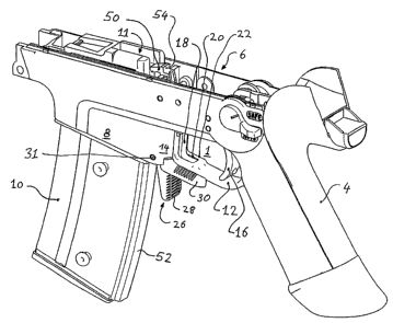
Fig. 1 shows the trigger area 1 of the weapon which, among others contains a
casing/frame
6 with a handhold 4 and a magazine well 8 as well as a removable magazine 10.
In the
trigger region 1 a trigger guard 12, which extends up to a casing region that
borders to the
magazine well 8, is arranged at the upper end of the handhold 4. Inside the
trigger guard the
trigger 16, as well as an operation element 18, is arranged that extends from
above from the
casing/handhold part 6 at the a casing region 14 along a clearance 20 of the
trigger guard 12,
whereby the trigger guard 12 itself contains in this area a thickening 22 that
partly
surrounds the bottom end of the operation element 18. The function of the
operation
element 18 is described further below. At the bottom side of the casing region
14 the
operation end 24 of a locking lever 26 emerges that serves for the spring-
loaded locking of
the magazine 10. A first operation element 28 as well as a second operation
element 30 is
arranged at the operation end 24. The locking lever 26 itself is arranged
rotatable between
the magazine well 8 and the trigger area 1 via a pin 31 that penetrates the
casing.
Figs. 2 and 3 show the function of the locking lever 26. Inside the casing
region 14 a lock
end 25 of the locking lever 26 extends that contains on its end that points
upwards a stop
end surface 27
CA 02545898 2006-05-12
WO 2005/050123 PCT/EP2004/012440
that engages in a corresponding mating surface 29 on the magazine 10 in the
depicted
locked position. The magazine 10 is in this way, with or without a similarly
constructed but
immobile stop coupling (not depicted) on the opposite side of the magazine 10,
secured in
the magazine well 8. The locking lever 26 itself is via a leg spring, which is
not depicted,
spring loaded in such a way that the lock end 25 engages with the stop end
surface 27 with
the magazine 10.
During the insertion of the magazine 10, the upper region of the corresponding
magazine
slides along the lock end 25 and rotates the lock end 26 slightly against the
spring loading
until it locks in a transverse groove 32 formed in the magazine, and the
magazine 10 is
secured from below via the mating surface 29 that is engaged with the stop end
surface 27.
For the release of the magazine 10, the gunman grabs with a free hand the end
of the
magazine 10 that protrudes from the magazine well 8, so that the thumb is
positioned at the
surface 36 of the first operation element 28 that faces the handhold 4. During
the holding of
the magazine, the thumb exerts an unlocking force E on the surface 36, which
rotates the
locking lever 26 against the spring force, so that the locking lever 25
disengages itself from
the magazine 10, the stop end surface 27 no longer engages with the mating
surface 29, and
the magazine 10 can be rotated, or pulled, respectively, out of the magazine
well 8.
Alternatively, the locking lever 26 can also be operated with the shooting
hand that holds
the frame. The unlocking force is thereby exerted by the second operation
element 30 as
(for example, the index finger or thumb) presses against an obliquely upwards
pointing
activation surfaces 38, 40 on one of the two activation wings 42, 44, and in
this way exerts
via the second operation element 30 a force F downwards,
CA 02545898 2006-05-12
WO 2005/050123 PCT/EP2004/012440
which likewise moves the locking lever 26 away from the locked position and
thereby
releases the magazine 10 that is fixated on the locking lever 25. Because
activation wings
42, 44 are provided to the right as well to the le$ of the trigger guard 12,
the unlocking can
be activated in numerous ways and independently from the handedness of the
gunman. The
surfaces 36, 38, and 40 are provided with ridges in order to improve the
handling.
Alternatively, however, they can also be provided with, not depicted, knurls,
naps, dents,
and/or handgrip troughs, and/or other surface structures that improve the
handling. There
are also embodiments with slip proof layers or inlaid elastomeric elements. In
another
embodiment (not depicted) the trigger guard 12 is interrupted and the formed
gap is
thereby filled in by the second operation element 30 which is constructed with
or without
activation wings 42, 44.
'The locking lever 26 itself is here fixated in the casing region 14 by the
pin 31 that
penetrates the casing 6 and which at the same time defines the pivot axis of
the locking
lever 26. The fixation can also take place through a (not depicted) axis stub
that is formed
on the locking lever 26 itself and that is in an appropriate way supported in
the casing
rotatably but is axially fixed. Since impacts and blows, i.e. accelerations,
of the weapon
cannot release the magazine lock, the locking lever 26 can be made from a
relatively light
plastic, for example, as a single piece in an injection molding process,
possibly with a
metal inlay. The spring force of the leg spring that acts on the locking lever
26, the length
of the locking land the operation ends 25, 24, the position of the pivot axis
and the
arrangement of the operation elements 28, 30, 36, 3 8, 40, 44, must be
adjusted to each other
in such a way that a possible secure fixation of the magazine 10 is guaranteed
during use
and that at the same time an activation of the locking lever 26 is possible,
without that the
CA 02545898 2006-05-12
WO 2005/050123 PCT/EP2004/012440
activation forces E and F become so large that an excessive strain of the
activating hand
results.
In casing 6 of the depicted embodiment example is also a bolt stop 46 that
holds the lock 48
open (fig. 2) after the firing of the last cartridge from the magazine 10. The
bolt stop 46
contains at its upper end a tongue 50 that points forwards and which is slid
upwards by a,
upwards moving, magazine follower 11 of the magazine 10 when it is in the
upper position
in case of an empty magazine 10. The tongue 50 itself protrudes only to such
an extent into
the magazine 10 that it is not touched by a back end of the cartridge cases
(not shown), but
only so far that the back end of the magazine follower 11, which extends in a
guidance
groove 52 in the magazine 10 that is hereto provided, lifts the tongue 50, so
that a,
backwards pointing, catch surface 54 protrudes into the path of the lock 48.
The lock 48
which, under spring loading, runs to the front, moves only so far to the front
that a, forward
pointing, front surface 56 rests on the catch surface 54 and stops the
movement. A part of
the bolt stop 46 protrudes downwards from the casing in the trigger region 1,
whereby the
operation element 18, which was already mentioned above, extends into the
trigger region
1 and extends along the region of the trigger guard 12 that is formed on the
casing 6. The
operation element 18 contains at its bottom end a guidance extension S 8 and
at its upper
end a handhold 60 which protrudes from the casing, which protrudes only a
little into the
trigger region 1.
The guidance extension 58 extends in a clearance 20 in the trigger guard 12
and is
surrounded by a tapered thickening 22. The bolt stop 46 is via a leg spring
63, of which one
leg is taken in by a groove 64 and the other leg is taken in by a suitable
place in the trigger
region. The force of the leg spring is adjusted in such a way that it
negotiates the spring
force due to the magazine follower 11 which moves upwards,
CA 02545898 2006-05-12
WO 2005/050123 PCT/EP2004/012440
so that the bolt stop 46 is slid upwards, but that is, however, not sufficient
to overcome the
friction force that acts between the front surface 56 of the lock 48 and the
catch surface 54
of the bolt stop 46. The lock 48 thus remains open when the emptied magazine
is removed
and is replaced with a full ammunition magazine. The magazine follower is no
longer
engaged with the tongue 50 of the bolt stop 46 in the case of a full magazine.
Conventionally, the bolt stop is released when the cocking handle (not
depicted), and
thereby the lack 48, is pulled back a little; as a result the catch surface 54
and the
corresponding neighboring front surface 56 of the lock 48 separate, the bolt
stop 46 snaps
downwards because of the spring loading, and the catch surface 54 lies outside
the path of
the lock 48 that is now moved forward (fig. 3) and feeds a cartridge into the
cartridge
chamber.
The guidance extension 58 now renders this pulling back of the cocking lever
unnecessary.
The bolt stop 46 can now namely be unlocked by that, for example, the trigger
finger
presses from above on the guiding extension 58, which moves downwards in the
clearance
20 and thereby pulls the catch surface 54 out of the engagement with the front
surface 56 of
the lock 48. The lock 48 is released and moves forward as described in the
above.
The "magazine hand" does not have to carry out a further action after the
insertion of the
full magazine 10 in this handling mode, but can again hold the weapon
immediately. On
the one hand, the reloading process will be thus accelerated and, on the other
hand, a target
can again be aimed at immediately with the help of both hands after the
magazine
replacement. Likewise, the state of the weapon can be "sensed" with the
guidance
extension 58: To the gunman it is usually
CA 02545898 2006-05-12
WO 2005/050123 PCT/EP2004/012440
not clear whether a shooting succession is, in spite of the activation of the
trigger 16, ended
because the magazine 10 is empty or because a loading jam has occurred. The
position of
the guiding extension 58 now allows a determination without that the weapon 3
has to be
examined in more detail. Namely, when the bolt stop 46 is in its described
working
position in case of an empty magazine 10, then the guiding extension 58
protrudes from the
clearance 20 into the trigger guard 12 (fig. 2); the gunman thus feels inside
the trigger
guard 12 the guiding extension 58 that sticks out of the thickening 22. When
the bolt stop is
in its rest position then the edge of the thickening 22 in the trigger guard
12 extends flush
with the upwards pointing surface of the guiding extension 58 (fig. 1); the
gunman feels a
smooth, continuous surface and knows that the interruption or the end of the
shooting
succession must have another cause (possibly a loading jam). That is, possible
operations
on the lock lever or other measures to negotiate such a loading jam are only
appropriate
when the position of the guiding extension 58 of the bolt stop 46 indicates
that the
magazine has not been emptied. In the other case the gunman must only replace
the
magazine 10, release the bolt stop 46, for example, via the guiding extension
58, and again
has a firing ready rifle at his disposal.
The handhold 60 mentioned in the above allows that the bolt stop 46 is slid
upwards also in
the case of a removed magazine and/or without engagement of the magazine
follower 11
and to keep the lock 48 open without holding the cocking handle, for example,
for
inspection of the barrel.
Since the bolt stop and the locking lever 26 operate independently from each
other for the
magazine locking, a clearance 62 that corresponds to the clearance 20 in the
trigger guard
12 is provided in between both the activation wings 42, 44. As depicted, this
clearance 62
can be constructed as an opening in the intermediate region 68 that connects
both
activation wings 42, 44.
to
CA 02545898 2006-05-12
WO 2005/050123 PCT/EP2004/012440
However, it can also be formed in such a way that both activation wings 42, 44
are
constructed as "fork spikes" which each extend from the locking lever 26 near
to the trigger
guard 12. .
In any case, the clearance 62 prevents that during the release of the trigger
bolt 46, for
example, dirt under the guidance extension 58 simultaneously moves the locking
lever 26
and the magazine disengages. It is likewise prevented that material, that
possibly is present
in between the bottom side of the trigger guard 12 and the intermediate region
68, engages
from below with the guiding extension 58 and unintentionally slides the bolt
stop 46 into
an operation position in which the lock 48 is blocked.
The in the embodiment example represented, the combination of locking lever 26
and bolt
stop 46 with their respective operation elements allows a very simple
execution of all
operations required for the reloading of a weapon. Nevertheless, the locking
lever 26 for
the spring loaded retaining of a removable ammunition magazine 10 can also be
constructed without the spring loaded bolt stop 46 or in connection with
another bolt stop,
for example, as described in DE 196 55 169 C2.
m