Note: Descriptions are shown in the official language in which they were submitted.
CA 02546029 2006-05-10
DEVICE AND METHOD FOR THE TRANSFERRING OF GRAIN FROM A GRAIN
BIN
FIELD OF THE INVENTION
The present invention relates to the transferring of grain or other
particulates, and particularly
to the transferring of grain or other particulates from a grain bin or other
storage location.
BACKGROUND OF THE INVENTION
Grain bins, which generally are in a cylindrical configuration and having a
conically shaped
roof can be in excess of 40 feet in diameter and in excess of 40 feet in
height, storing for example,
in excess of 30,000 bushels of grain or other particulate material. The bin
floor, for example, may
be formed by a poured concrete slab. The bin walls which are securely anchored
to the bin floor are
generally made of curved, corrugated stainless steel panels which are bolted
or joined together to
form a continuous curved wall for the bin. An access door at the bottom of the
bin is generally
provided to allow access for workers and equipment onto the bin floor, for
example, when the bin
is substantially empty. The roof of the bin will generally have an access hole
at the top to allow
access for workers and equipment.
Grain piled against a bin wall will exert outward pressure on the bin wall. It
will be
appreciated that this force can be significant, and in the case of large grain
bins, this force is
sufficient to deform bin walls if care is not taken during the grain loading
and unloading processes
to ensure that the grain is evenly distributed in the bin at all times during
the loading and unloading
processes. To minimize the risk of deformation, bins are preferably loaded and
unloaded from the
middle of the bin, to ensure that grain is at all times distributed throughout
the bin during the loading
and unloading processes, to thereby equalize to the extent possible the
loading on the bin walls.
While loading the bin from a position approximately in the middle of the grain
pile is readily
achieved by loading the grain into the bin by means of a conveyor, the
delivery end of which is
positioned at the top center of the bin (for example, when the grain is loaded
from a conveyor which
1
CA 02546029 2006-05-10
discharges the grain through a top access door in the roof of the bin), which
conveyor delivery end
is equi-distant the bin walls, so that when the grain falls to the bin floor a
pile is formed which
continually expands to the bin walls to substantially evenly distribute the
grain in the bin and as the
pile continues to grow, to substantially evenly load the bin walls. This
allows the outward pressure
on any portion of the wall of the bin to be offset and balanced by the outward
pressure on that
portion of the wall of the bin which is directly opposite that portion.
During the removal of grain from the bin, continuously unloading the bin from
the center of
the grain pile, while necessary to minimize the risk of deformation of the bin
wall, is more difficult.
SUMMARY OF THE INVENTION
Accordingly, one object of the present invention is to provide an improved
device and
method for transferring grain or other particulates from a grain bin.
Another object of the present invention is to provide an improved device and
method for
effectively providing for the transfer of grain or other particulates from a
grain bin, while minimizing
the loading on the bin walls, and thus reducing the risk of deformation of the
bin wall during the
loading and unloading processes.
According to one aspect of the present invention, there is provided a grain
transfer system
for a grain bin having an interior for holding a quantity of grain, the system
comprising an inlet in
a sidewall of the grain bin; an outlet in another sidewall of the grain bin
opposite the inlet; a grain
transfer tube, the tube being inserted through each of the inlet and the
outlet so as to be positioned
substantially within the interior of the grain bin, the grain transfer tube
having at least one opening
therein for permitting grain in the grain bin to enter into an interior of the
tube; at least one blower
for communicating with the grain transfer tube, the at least one blower being
positioned at an end
of the grain transfer tube positioned at the inlet, and for providing a high
powered air stream through
the grain transfer tube to entrain and propel the grain within the tube to the
outlet; and a suction hose,
coupled with the outlet, for drawing grain in the grain bin into the tube for
transferral through the
outlet to a remote location.
2
CA 02546029 2006-05-10
According to another aspect of the present invention, there is provided a
grain transfer system
for a grain bin having an interior for holding a quantity of grain, the system
comprising an inlet in
a sidewall of the grain bin; an outlet in another sidewall of the grain bin
opposite the inlet; a grain
transfer tube, the tube being inserted through each of the inlet and the
outlet so as to be positioned
substantially near a bottom portion of the interior of the grain bin, the
grain transfer tube having at
least one opening therein for permitting grain in the grain bin to enter into
an interior of the tube; at
least one blower for communicating with the grain transfer tube, the at least
one blower being
positioned at an end of the grain transfer tube positioned at the inlet, and
for providing a high
powered air stream through the grain transfer tube to entrain and propel the
grain within the tube to
the outlet; and a suction hose coupled with the outlet, to create, in
combination with the at least one
blower, a vacuum force for drawing the grain in the grain bin to enter into
the interior of the tube,
and for propelling the drawn grain along the tube through the outlet to a
remote location.
According to another aspect of the present invention, there is provided a
method of
transferring grain from a grain bin having an interior for holding a quantity
of grain, the method
comprising positioning an inlet and an outlet in opposed sidewalls of the
grain bin; inserting a grain
transfer tube through each of the inlet and the outlet so as to be positioned
substantially within the
interior of the grain bin, the grain transfer tube having at least one opening
therein for permitting
grain in the grain bin to enter into an interior of the tube; placing at least
one blower at an end of the
grain transfer tube positioned at the inlet; utilizing the at least one blower
to draw an air stream
through the grain transfer tube; and attaching a suction hose to the outlet to
draw, in combination
with the at least one blower, grain in the grain bin into the tube for
transferral through the outlet to
a remote location.
According to a further aspect of the present invention, there is provided a
grain bin assembly
for transferring grain from a grain bin having an interior for holding a
quantity of grain comprising
an inlet in a sidewall of the grain bin; an outlet in another sidewall of the
grain bin opposite the inlet;
a grain transfer tube, the tube being inserted through each of the inlet and
the outlet, the grain
transfer tube having at least one opening therein for permitting grain in the
grain bin to enter into an
interior of the tube; at least one blower for communicating with the grain
transfer tube, the at least
3
CA 02546029 2006-05-10
one blower being positioned at an end of the grain transfer tube positioned at
the inlet, and for
providing an air stream through the grain transfer tube; and a suction hose
coupled with the outlet,
to create, in combination with the at least one blower, a vacuum force for
drawing the grain in the
grain bin to enter into the interior of the tube, and for propelling the drawn
grain along the tube
through the outlet to a remote location.
The advantage of the present invention is that it provides an improved device
and method
for transferring grain or other particulates from a grain bin.
A still further advantage of the present invention is that it provides an
improved device and
method for effectively providing for the transfer of grain or other
particulates from a grain bin, while
minimizing the loading on the bin walls, and thus reducing the risk of
deformation of the bin wall
during the loading and unloading processes.
BRIEF DESCRIPTION OF THE DRAWINGS
A preferred embodiment of the present invention is described below with
reference to the
accompanying drawings, in which:
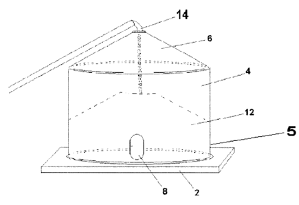
Figure 1 is a view of a typical grain bin being loaded with grain from an
overhead conveyor
system;
Figure 2 is a cross-sectional view of the bottom portion of a grain bin
illustrating one
embodiment of the present invention with a tube mounted to the bin floor, and
extending
across and outside of the bin;
Figure 3 is a cross-sectional view of the bottom portion of a grain bin
illustrating the
embodiment of Figure 2, with a blower unit attached on one end of the tube,
and a grain vac
hose attached to the other end;
Figure 4 is a magnified view of one end of the tube illustrated in Figure 2,
illustrating the
4
CA 02546029 2006-05-10
orifice, the orifice cover (in the closed position), and one embodiment of a
mechanism for
moving the orifice cover between the open and closed position;
Figure 5 is a magnified view of the end of the tube illustrated in Figure 4,
the orifice cover
being in the open position;
Figure 5A is a cross-sectional view of one embodiment of the orifice, screen
and external
orifice cover;
Figure 5B is a side view of one embodiment of the external orifice cover in
the closed
position;
Figure 5C is a side view of one embodiment of the external orifice cover in
the open position;
Figure 5D is a cross-sectional view of an alternative embodiment of the
orifice, screen and
internal orifice cover;
Figure 6 is a cross-sectional view of the bottom portion of a grain bin
illustrating an
alternative embodiment of the present invention with an inlet tube mounted to
the bin floor,
and extending outside of the bin and approximately halfway across the bin, and
an outlet tube
positioned within the floor of the bin, extending from outside of the bin to a
hole in the bin
floor positioned approximately in the center of the bin;
Figure 7 is a cross-sectional view of the embodiment of Figure 6, with a
blower unit attached
on one end of the tube, and a grain vac hose attached to the other end;
Figure 8 is a magnified view of one end of the tube illustrated in Figure 6,
illustrating the
orifice, the internal orifice cover (in the closed position), and one
embodiment of a
mechanism for moving the internal orifice cover between the open and closed
position; and
Figure 9 is a magnified view of the end of the tube illustrated in Figure 6,
the internal orifice
5
CA 02546029 2006-05-10
cover being in the open position;
DESCRIPTION OF THE PREFERRED EMBODIMENT
Referring to Figure 1, positioned upon a concrete pad 2, is a typical grain
bin 4, it being
understood that grain bins may be positioned upon other suitable pads or
materials known to a person
skilled in the art. The vertical walls 5 and conical roof 6 of the typical
grain bin 4 are generally made
of corrugated stainless steel or other suitable material, known to a person
skilled in the art. An access
door 8 provides access for personnel and equipment into the interior of the
grain bin 4 and an access
port 10 at the top of the grain bin 4 permits grain to be transferred from a
conveyor system 14 into
the interior of the grain bin 4 for storage, which typically forms a pile 12
generally centered within
the grain bin 4.
Referring to Figure 2, a metal tube 16 extends across the concrete pad 2 (or
other floor
material for the bin, hereinafter referred to as the "concrete pad"), and is
securely anchored thereto
by means of anchors, straps, bolts or other devices known to a person skilled
in the art, so that the
tube 16 remains stationary during the grain loading and unloading processes.
In the preferred
embodiment, the tube is of generally circular cross-section and is made of
aluminum, or stainless
steel, it being understood that alternative materials and cross-sections may
be utilized in alternative
embodiments of the present invention. The tube 16 extends through orifices
(not shown) in the grain
bin walls 5 on opposite sides of the grain bin 4, a secure and weather-tight
seal being provided at the
orifice between the tube 16 and the grain bin wa115, in a manner known to a
person skilled in the art.
Removable caps 17 on both ends of the tube 16 are provided to keep varmints,
the weather and other
materials from accessing the tube 16 and the interior of the grain bin 4.
Referring to Figure 3, in the preferred embodiment, a large upwardly directed
orifice 18 in the
tube 16, which may be opened or closed as more fully described herein,
permits, when opened, grain
to flow or be drawn into the tube 16, the orifice being preferably of a
generally ovoid or elliptical
shape, it being understood that a wide range of orifice shapes may be utilized
in alternative
embodiments of the present invention. In operation, the removable caps 17 are
removed from both
ends of the tube 16, a grain vac hose 22 is connected to one end of the tube
16 in a manner known to
6
CA 02546029 2006-05-10
a person skilled in the art, the external cover 20 is positioned in the open
position as illustrated in
Figure 3 and in one embodiment, a blower or fan 24 is attached to the other
end of the tube 16 in a
manner known to a person skilled in the art. The blower or fan 24, when
activated, provides air fi=oin
outside of the bin 4 through one end of the tube 16, and past the orifice 18,
and the grain vac (not
shown) when activated, by means of the grain vac hose 22, provides suction
from the other end of
the tube 16, the blower or fan 24 combining with the grain vac (by means of
the grain vac hose 22)
to move a significant quantity of air past the orifice 18 and thereby draw
grain through the orifice 18
into, and through the tube 16 in the direction of the grain vac hose 22, for
subsequent transfer to the
grain vac hose 22, and thereafter to the grain vac in a manner known to a
person skilled in the art. In
an alternative embodiment, rather than attaching a blower or fan 24 to the end
of the tube 16 as
previously described, after the removable caps 17 have been removed and a
grain vac hose 22
attached on one end of the tube 16, the other end of the tube 16 is left open,
permitting air from
outside of the bin 4 to enter the tube 16 by way of the partial vacuum created
by the operation of the
grain vac (by means of the grain vac hose 22).
In the preferred embodiment, a moveable external cover 20 is provided which is
curved to
conform with the outer surface of the tube and extending part of the way
around the circumference
of the tube to fully cover the orifice when in the closed position, to thereby
prevent grain or other
particulates from entering the tube 16 while the external cover 20 is in the
closed position. In the
preferred embodiment, the external cover 20 is made of aluminum, or stainless
steel, it being
understood that alternative materials may be utilized in alternative
embodiments of the present
invention. As illustrated in Figures 3 and 5, the external cover 20, is shown
in the open position
(positioned adjacent to the orifice 18), and as illustrated in Figures 2 and
4, the external cover 20, is
shown in the closed position (the external cover 20 positioned directly above
the orifice 18). In the
preferred embodiment, the external cover 20 is supported by and may slide
along an external
horizontal guideway 26, which may be made of, for example, channel or flat bar
welded or otherwise
securely fastened to the outside of the tube 16, it being understood that
alternative guideways may be
utilized to support and permit the movement of the external cover 20 between
an open and closed
position. A handle 28 , fastened to the external cover, and extending through
the exterior wall of the
bin may be utilized to move the external cover 20 between the open and closed
position as needed,
it being understood that alternative mechanisms may be utilized to move the
external cover between
7
CA 02546029 2006-05-10
the open and closed position.
As illustrated in Figures 5B and 5C, in one embodiment of the present
invention, a coarse
screen 30 is provided, and is securely attached to the tube 16 covering the
orifice 18, to prevent large
objects from entering into the tube 16, the coarseness of the screen being
such that it would readily
permit grain or other particulates to easily flow therethrough, while at the
same time, preventing large
objects from passing therethrough. As illustrated in Figures 5A, 5B and 5C,
the screen is positioned
to cover the entire orifice, and in such a manner as to permit the external
cover 20 to easily slide over
the screen between the closed position illustrated in Figure 5A and the open
position illustrated in
Figure 5B without interference between the screen and the external cover 20,
as illustrated in Figure
5A.
In an alternative embodiment of the present invention as illustrated in
Figures 6 and 7, an
outlet tube 34 extends beneath or within the pad 2 from an area outside of the
bin wa115, beneath the
bin wa115 to an area near the center of the bin where there is located an
opening 36 in the concrete
pad 5, the outlet tube 34 having an orifice 18 therein substantially
corresponding with the opening 36
in the concrete pad 2, to permit grain or other particulates to flow into the
outlet tube 34 as described
herein. An inlet tube 32 extends from outside of the bin wa115 on the opposite
side of the bin, through
the bin wa115, and extends to an area proximate to the opening 36 in the
concrete pad 2. During non-
use, the outlet tube 34 and inlet tube 32 are both capped with removable caps
17 to keep varmints,
the weather and other materials from accessing the tube 16 and the interior of
the grain bin 4.
Referring to Figures 6, 7, 8, and 9, in this embodiment, in operation, the
removable caps 17
are removed from the ends of the inlet tube 32 and outlet tube 34, a grain vac
hose 22 is connected
to the external end of the outlet tube 16 in a manner known to a person
skilled in the art, the internal
orifice cover 38 is positioned in the open position as illustrated in Figure 7
and Figure 9 and in one
embodiment, a blower or fan 24 is attached to the external end of the inlet
tube 16 in a manner
known to a person skilled in the art. The blower or fan 24 provides air from
outside of the bin 4
through the external end of the inlet tube 16 to an area proximate the opening
36 in the concrete pad
and orifice 18, and a grain vac (not shown), by means of the grain vac hose
22, provides suction from
the external end of the outlet tube 34, the blower or fan 24 providing airflow
proximate the opening
8
CA 02546029 2006-05-10
36 in the concrete pad and orifice 18 which when combined with the suction
provided by the grain
vac (by means of the grain vac hose 22) provides for a significant quantity of
air passing the orifice
18 and thereby drawing grain through the orifice 18 into, and through the
outlet tube 34 in the
direction of the grain vac hose 22, for subsequent transfer to the grain vac
hose 22, and thereafter to
the grain vac in a manner known to a person skilled in the art. In an
alternative embodiment, rather
than attaching a blower or fan 24 to the external end of the inlet tube 34 as
previously described, after
the removable caps 17 have been removed and a grain vac hose 22 attached on
one end of the outlet
tube 36, the inlet tube 16 is left open, permitting air from outside of the
bin 4 to enter the inlet tube
34 by way of the slight vacuum created within the bin by the operation of the
grain vac (by means of
the grain vac hose 22). The embodiment of the present invention illustrated in
Figures 6, 7, 8, and
9 may readily be adapted for utilization in the retro-fitting of grain bins
which have, or previously
had, installed therein grain augers beneath or within the concrete pad or
floor of the bin, the retro-fit
including the step of removing the auger and using the auger housing (still
positioned in the concrete
pad or floor) as the outlet tube, or alternatively, inserting an outlet tube
of slightly smaller diameter
within such housing.
As illustrated in Figure 9, the internal cover 38 is shown in the open
position (positioned
adjacent to the orifice 18), and as illustrated in Figure 8, the internal
cover 38 is shown in the closed
position (the internal cover 38 positioned directly below the orifice 18). In
this embodiment, as
illustrated in Figure 5D, the internal cover 38 is supported by and may slide
along an internal
guideway 40, which may be made of, for example, channel or flat bar welded or
otherwise securely
fastened to the inside wall of the outlet tube 34, it being understood that
alternative guideways may
be utilized to support and permit the movement of the internal cover 20
between an open and closed
position. A handle 28 accessible to an operator outside of the bin wall 5,
fastened to the internal
cover, and extending within the outlet tube 34 through the exterior wall 5 of
the bin may be utilized
to move the internal cover 38 between the open and closed position as needed,
it being understood
that alternative mechanisms may be utilized to move the external cover between
the open and closed
position.
The present invention has been described herein with regard to preferred
embodiments.
However, it will be obvious to persons skilled in the art that a number of
variations and modifications
9
CA 02546029 2006-05-10
can be made without departing from the scope of the invention as described
herein.