Note: Descriptions are shown in the official language in which they were submitted.
CA 02546531 2008-04-25
79350-202
METHOD AND SYSTEM FOR WELLBORE COMMUNICATION
BACKGROUND OF THE INVENTION
[0002] The present invention relates to telemetry systems for use in wellbore
operations.
More particularly, the present invention relates to telemetry systems for
providing power to
downholc opcrations and/or for passing signals between a position in a
wellbore penetrating a
subterranean formation and a surface unit
[0003] Wells are generally drilled into the ground to recover natural deposits
of hydrocarbons
and other desirable materials trapped in geological formations in the Earth's
crust. A well is
typically drilled by advancing a drill bit into the earth. The drill bit is
attached to the lower end
of a "drill string" suspended from a drilling rig. The drill string is a long
string of sections of
drill pipe that are connected together end-to-end to form a long shaft for
driving the drill bit
further into the earth. A bottom hole assembly (BHA) containing various
instrumentation and/or
mechanisms is typically provided above the drill bit. Drilling fluid, or mud,
is typically pumped
down through the drill string to the drill bit. The drilling fluid lubricates
and cools the drill bit,
and it carries drill cuttings back to the surface in the annulus between the
drill string and the
borehole wall.
1
CA 02546531 2008-04-25
79350-202
[0004] During conventional measurement while drilling (MWD) or logging while
drilling
(LWD) operations, signals are passed between a surface unit and the BHA to
transmit, for
example commands and information. Typically, the surface unit receives
information from the
BHA and sends command signals in response thereto. Communication or telemetry
systems
have been developed to provide techniques for generating, passing and
receiving such signals.
An example of a typical telemetry system used involves mud-pulse telemetry
that uses the drill
pipe as an acoustic conduit for mud pulse telemetry. With mud pulse telemetry,
mud is passed
from a surface mud pit and through the pipes to the bit. The mud exits the bit
and is used to
contain formation pressure, cool the bit and lift drill cuttings from the
borehole. This same mud
flow is selectively altered to create pressure pulses at a frequency
detectable at the surface and
downhole. Typically, the operating frequency is in the order 1-3 bits/sec, but
can fall within the
range of 0.5 to 6 bits/sec. An example of mud pulse telemetry is described in
US Patent No.
5,517,164.
[0005] In conventional drilling, a well is drilled to a selected depth, and
then the welibore is
typically lined with a larger-diameter pipe, usually called casing. Casing
typically consists of
casing sections connected end-to-end, similar to the way drill pipe is
connected. To accomplish
this, the drill string and the drill bit are removed from the borehole in a
process called "tripping."
Once the drill string and bit are removed, the casing is lowered into the well
and cemented in
place. The casing protects the well from collapse and isolates the
subterranean formations from
each other. After the casing is in place, drilling may continue or the well
may be completed
depending on the situation.
[0006] Conventional drilling typically includes a series of drilling,
tripping, casing and
cementing, and then drilling again to deepen the borehole. This process is
very time consuming
2
CA 02546531 2008-04-25
79350-202
and costly. Additionally, other problems are often encountered when tripping
the drill string.
For example, the drill string may get caught up in the borehole while it is
being removed. These
problems require additional time and expense to correct.
[0007] The term "casing drilling" refers to the use of a casing string in
place of a drill string.
Like the drill string, a chain of casing sections are connected end-to-end to
form a casing string.
The BHA and the drill bit are connected to the lower end of a casing string,
and the well is
drilled using the casing string to transmit drilling fluid, as well as axial
and rotational forces, to
the drill bit. Upon completion of drilling, the casing string may then be
cemented in place to
form the casing for the wellbore. Casing drilling enables the well to be
simultaneously drilled
and cased. Examples of such casing drilling are provide in US Patent No.
6,419,033, US Patent
Application No. 20040104051 and PCT Patent Application No. W000/50730.
[0008] Despite the advances in casing drilling technology, current casing
drilling systems are
unable to provide high speed communication between the surface and the bottom
hole assembly.
Therefore, what is needed is a system and method to provide a casing drilling
system with high
speed, low attenuation rate and/or enhanced band width signal capabilities.
SUMMARY OF INVENTION
[0009) In at least one respect, the present invention includes a communication
system and
method for a casing while drilling system. The casing while drilling system is
adapted to
advance a into a subsurface formation via a casing. The communication system
includes a high
frequency modulator and a transducer. The modulator is positioned in the
bottom hole assembly
and adapted to generate a mud pulse by selectively restricting the mud flow
passing
therethrough. The transducer is adapted to detect the mud pulse generated by
the modulator.
3
CA 02546531 2008-04-25
79350-202
[0010] In another aspect, the invention relates to a
method of communicating with a bottom hole assembly of a
casing while drilling system. The casing while drilling
system is adapted to advance the bottom hole assembly into a
subsurface formation via a casing. The method includes
generating mud pulses at predefined frequencies by
selectively restricting a mud flow passing through a
modulator of the bottom hole assembly and detecting the mud
pulses at the surface.
In another aspect of the invention, there is
provided a communication system for use in a drilling
system, the communication system comprising: a modulation
means positioned at a downhole end of the drilling system
and operable to alter mud flow rate to generate at least one
mud pulse, the downhole end of the drilling system coupled
to the Earth's surface at the end of a casing; and a
demodulation means positioned uphole and adapted to detect
the mud pulse, wherein the modulation means generates mud
pulses at a frequency selected such that the at least one
mud pulse is attenuated by substantially a same amount as in
a drill pipe having a smaller internal diameter and
substantially a same length as the casing.
In still another aspect of the invention, there is
provided a communication system for a casing while drilling
system, the casing while drilling system adapted to advance
a bottom hole assembly into a subsurface formation via a
casing, the communication system comprising: a modulator
adaptable to operate at selected frequencies, wherein the
modulator is positioned in the bottom hole assembly the
bottom hole assembly coupled to a casing, the casing
extending a selected length toward the surface from within a
wellbore, the modulator adapted to generate a mud pulse by
4
CA 02546531 2008-04-25
79350-202
selectively restricting mud flow passing therethrough; the
frequencies selected such that the at least one mud pulse is
attenuated by substantially a same amount as in a drill pipe
having a smaller internal diameter and substantially a same
length as the casing and a transducer adapted to detect the
mud pulse generated by the modulator.
In a further aspect of the invention, there is
provided a method of communicating with a bottom hole
assembly of a casing while drilling system, the casing while
drilling system adapted to advance the bottom hole assembly
into a subsurface formation via a casing, comprising:
generating mud pulses at a high frequency by selectively
restricting mud flow passing through a modulator of the
bottom hole assembly, the frequency selected such that the
mud pulses is attenuated by substantially a same amount as
in a drill pipe having a smaller internal diameter and
substantially a same length as the casing; and detecting the
mud pulses at the surface.
In another aspect of the invention, there is
provided a drilling system that advances a bottom hole
assembly having a drill bit into a subsurface formation, the
bottom hole assembly suspended at an end of a casing, the
system comprising: a communication means for generating mud
pulses at frequencies selected such that the mud pulses is
attenuated by substantially a same amount as in a drill pipe
having a smaller internal diameter and substantially a same
length as the casing; an assembly for drilling, measurement,
or formation evaluation; and a mud motor for converting mud
flow into rotation of the drill bit, wherein the
communication means is uphole relative to the mud motor and
wherein the communication means is in communication with
said assembly.
4a
CA 02546531 2008-04-25
79350-202
BRIEF DESCRIPTION OF DRAWINGS
So that the above recited features and advantages
of the present invention can be understood in detail, a more
particular description of the invention, briefly summarized
above, may be had by reference to the embodiments thereof
that are illustrated in the appended drawings. It is to be
noted, however, that the appended drawings illustrate only
typical embodiments of this invention and are therefore not
to be considered limiting of its scope, for the invention
may admit to other equally effective embodiments.
FIGURE 1 is a schematic view, partially in cross-
section, of a rig having a casing drilling system for
drilling a wellbore, the casing drilling system provided
with a casing drilling communication system.
FIGURE 2A is a detailed view of the casing
drilling system of FIGURE 1, the casing drilling system can
entail a drilling, measurement, and/or formation evaluation
assembly such as a rotary steerable (RSS), measurement while
drilling (MWD) and/or logging while drilling (LWD) system
and a modulator.
4b
CA 02546531 2006-05-11
[0011] FIGURE 2B is a detailed view of the casing drilling system of FIGURE 1,
wherein the
casing drilling communication system is run with a mud motor or turbo drill
and the
communication system is located uphole relative to the mud motor.
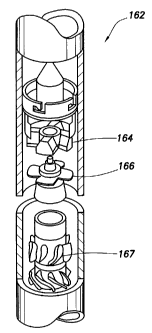
[0012] FIGURE 3 is a detailed, exploded view of the modulator of Figure 2
having a stator
and a rotor.
[0013] FIGURE 4A is a detailed view of the modulator of Figure 2 with the
rotor in the open
position relative to the stator.
[0014] FIGURE 4B is a detailed view of the modulator of Figure 2 with the
rotor in the
closed position relative to the stator.
[0015] FIGURES 5A-D are schematic views of the rotor and stator of Figure 3
depicting the
movement of the rotor relative to the stator.
[0016] FIGURES 6A-D are graphs depicting the relationship between pressure
versus time
for the rotors and stators depicted in Figures 5A-D, respectively.
[0017] FIGURE 7 is a graph depicting signal strength versus depth at a first
frequency and bit
rate.
[0018] FIGURE 8 is a graph depicting signal strength versus depth at a second
frequency and
bit rate.
DETAILED DESCRIPTION
[0019] Referring to Figure 1, a casing drilling system 100 includes a rig 102
with a bottom
hole assembly (BHA) 104 deployed into a borehole 106 via a casing 108. The rig
102 has a
traveling hook/block 126, top drive 128, guide rail and top drive/block dolly
130 and draw works
131. A casing drive head/assembly 132 operatively connects the casing to the
top drive 128.
CA 02546531 2006-05-11
The casing 108 extends through a conductor pipe 134. Casing slips 136 are used
to suspend the
casing 108 string when adding a new joint of casing as drilling depth
increases.
[0020] In one embodiment, the BHA 104 includes a drill bit 118 at a downhole
end thereof, a
rotary steerable (RSS), measurement while drilling (MWD) and/or logging while
drilling (LWD)
assembly 125, and an under reamer 122. A BHA latch & seal assembly 124
operatively connects
the BHA 104 to the casing 108. Preferably, the latch & seal assembly 124 and
the BHA 104 are
retrievable through the casing 108. The MWD/LWD assembly 125 preferably
includes or
communicates with a telemetry system or modulator, which is described in
detail below, for
communication with an acquisition and demodulation unit 127. The acquisition
and
demodulation unit 127 typically resides in a surface unit, cabin or enclosure
(not shown).
[0021] A surface mud pit 110 with a mud 112 therein is positioned near the rig
102. Mud 112
is pumped through feed pipe 114 by pump 116 and through the casing 108 as
indicated by the
arrows. Mud 112 passes through the BHA 104, out the drill bit 118 and back up
through the
borehole 106. Mud 112 is then driven out an outlet pipe 120 and back into mud
pit 110.
[0022] The drill bit 118 advances into a subterranean formation F and creates
a pilot hole 138.
The under reamer 122 advances through the borehole 106, expands the pilot hole
138 and creates
an under-reamed hole 140. The BHA 104 is preferably retrievable through the
casing 108 on
completion of the drilling operation. The under reamer 122 is preferably
collapsible to facilitate
retrieval through the casing 108.
[0023] Referring now to Figure 2A depicts a portion of the casing drilling
system 100 of
Figure 1 in greater detail. As mud 112 is pumped from feed pipe 114 through
pump 116, it
passes by a pressure transducer 142 and down through the casing 108 to an RSS,
MWD, and/or
LWD assembly 125 as indicated by arrows 148, 150, and 152. The mud 112 passes
through the
6
CA 02546531 2008-04-25
79350-202
BHA 104, exits the drilling bit 118 and retums through borehole 106 as
indicated by arrows 154,
156 and 158.
[00241 The RSS, MWD, and/or LWD assembly 125 uses a mud pulse system, such.as
the one
described in US Patent No. 5,517,464. The RSS,
MWD, and/or LWD assembly 125 includes a modulator 162 adapted to communicate
with a
surface unit (not shown). As mud 112 passes through the modulator 162, the
modulator 162
restricts the flow of the mud 112 and hence the pressure to generate a signal
that travels back
through the casing 108 as indicated by arrows 160 and 163. The pressure
transducer 142 detects
the changes in mud pressure caused by the modulator 162. The acquisition and
demodulation
unit 127 processes the sigtial thereby alluwiiig tlie 104 to coiruuuiiicate to
the surface tlirougli
the unit 127 for uphole data collection and use.
[0025] Referring now to Figure 2B, an alternative embodiment is shown wherein
a BHA 204
inchides a drilling, measurement, and/or formation evaluation assembly 225,
such as RSS,
MWD, and/or LWD, a mud motor or turbo-dril1210, a drill bit 218, an under-
reamer 222, and a
data transmission module 224. The mud motor 210 is located downhole or below a
casing
drilling modulator 262, which is similar to the modulator 162 of Figure 2A.
Using a mud or
drilling motor, such as the mud motor 210, provides the advantage of reducing
the amount of
rotations on the casing 108. In one embodiment, the modulator 262 communicates
with the
transmission module 224, which is in communication with other components or
elements of the
BHA 204. In an alternative embodiment, the modulator 262 communicates directly
with the
other elements in the BHA 204 including the RSS, MWD, and/or LWD assembly 225
through=
various means including wired or wireless such as electromagnetic or
ultrasonic methods. The
scope of the present invention is not limited by the mean used for
communication, which
7
CA 02546531 2008-04-25 ,;
79350-202
includes but is not limited to transmission through wired methods or wireless
methods, which
could include electromagnetic, ultrasonic or other means, or a combination
thereof, such a wired
and wireless or ultrasonic and electromagnetic combined with wired
communication.
Positioning the mud motor 210 downhole relative to the modulator 262 is the
present
embodiment which limits signal attenuation and produces the higher data rate
and depth
capability.
100261 Referring now to Figure 3, the modulator 162 of Figure 2A and modulator
262 of
Figure 2B are depicted in greater detail. In each of the embodiments set forth
herein, the
modulator are similar in operation. Accordingly, even though the operation of
one of the
modulators is discussed in detail, the operation and results are applicable to
similar types of
modulators shown in alternative embodiments. The modulator 162 includes a
stator 164, rotor
166 and turbine 167. The modulator 162 may be, for example, of the type
described in
US Patent No. 5,517,464. In one embodiment, the
modulator 162 is preferably a rotary or siren type modulator. Such modulators
are typically
capable of high speed operation, which can generate high frequencies and data
rates.
Alternatively, in another embodiment conventional "poppet" type or
reciprocating pulsers may
be used, but they tend to be limited in speed of operation due to limits of
acceleration/deceleration and motion reversal with associated problems of
wear, flow-erosion,
fatigue, power limitations, etc.
[0027] As the mud flow passes through the turbine 167, the mud flow turns the
turbine 167
and the rotation of the turbine 167 caused by the flow of mud generates power
that can be used
to power any required part of portion the BHA 104, including the rotor 166 of
modulator 162.
8
CA 02546531 2006-05-11
[0028] Figures 4A and 4B show the position of the rotor 166 and stator 164. In
Figure 4A,
the rotor 166 is in the open position. In other words, the rotor 166 is
aligned with the stator 164
to permit fluid to pass through apertures 168 therebetween.
[0029] In Figure 4B, the rotor 166 is in the closed position, such that the
apertures 168 are
blocked, at least partially. In other words, the rotor 166 is mis-aligned with
respect to the stator
164 to block at least a portion of the fluid passing through apertures 168
therebetween. The
movement between the open and closed position creates a`pressure pulse.' This
pressure pulse
is a signal detectable at the surface, and is used for conununication.
[0030] Referring now to Figures 5A-D, the flow of fluid past the rotor 166 and
stator 164 is
shown in greater detail in Figures 5A-D. In the open position (Fig. 5A), fluid
passes with the
least amount of restriction past stator 164 and rotor 166.
[0031] As the rotor 166 rotates and blocks a portion of the aperture 168 (Fig.
5B), fluid is
partially restricted, thereby causing a change in pressure over time. The
rotor 166 then rotates to
a more restricted or closed position (Fig. 5C) and restricts at least a
portion of the fluid flow.
The rotor 166 advances further until it returns to the unobstructed position
(Fig. 5D).
[0032] Referring now to Figures 6A-D, the change in pressure over time is
displayed in
graphs of pressure-versus-time plots of the fluid flow for each of the rotor
positions of Figures
5A-D, respectively.
[0033] The following equations show the general effect of various parameters
of the mud
pulse signal strength and the rate of attenuation:
9
CA 02546531 2006-05-11
S = SO exp [-4 aE F (Dld) 2 (l]K)]
where
5= signal strength at a surface transducer;
so = signal strength at the downhola modulator;
F = carrierfrequancy of the MWD signal expressed
in Hertz;
D = measured depth between the surface transduc-
er and the dvwnhole modulator;
d inside diameter of the drill pipe (same units as
measured depth);
p, - plastic viscosity of the drilling fluid;. and
K bulk modulus of the volume of mud above the
modulator,
and by the modulator signal pressure relationship
~o = (pmud X Q 2 YA 2
where
so = signal strength at the downhole modulator;
pmud= density of the drilling fluid;
Q = volume flow rate of the drilling fluid; and
A = the flow area with the modulator in the "closed"
position
[0034] The foregoing relationships demonstrate that a larger diameter of pipe,
such as the
casing 108, makes higher carrier frequencies and data rates possible since the
attenuation rate is
lower for larger pipe diameters. Thus, for the specific application of casing
drilling, the effect of
CA 02546531 2006-05-11
the inside diameter "d", as shown in Fig. 2, makes higher carrier frequencies
(hence, data rates)
possible since the rate of attenuation is much less compared to conventional
drill pipe.
Accordingly, the ability to transmit at high frequencies and, hence the scope
of the present
invention, is determined by the foregoing relationships. The specific data
rates provided below
are for illustration purposes and not intended as a limiting example.
[0035] Referring now to Figures 7 and 8, graphs comparing the signal strength
(y-axis) at
various depths (x-axis) for a drill pipe in comparison to a casing. Figure 7
shows the signal
strength for a 5" drill pipe (170) and a 7" casing (172). A minimum level
(174) for detecting
signal strength is also depicted. The graph illustrates the effect diameter
has on signal strength in
a 24hz-12 bit/second deep water application using synthetic oil based mud.
This shows that with
the larger internal diameter of casing, 12 bit/sec telemetry rate is possible
to about 20000 feet as
compared to the smaller drill pipe diameter where 12 bit/sec is limited to
about 13000 feet.
Thus, the communication system described herein in this example can operate in
the range of 1
bit/sec up to 12bits/sec depending on the casing diameter and depth.
[0036] Figure 8 shows the signal strength for a 5" drill pipe (180) and a 7"
casing (182). A
minimum level (184) for detecting signal strength is also depicted. The graph
illustrates the
effect diameter has on signal strength in a l hz-1 bit/second deep water
application using
synthetic oil based mud. Typically, telemetry with drill pipe will be limited
to l bit/sec, hence
there is one order of magnitude higher data rate possible in these conditions
with casing as
compared to drill pipe. There is also an approximately four-fold increase in
signal amplitude
with casing as compared to drill-pipe for 1 Hz telemetry.
11
CA 02546531 2006-05-11
[0037] It should be noted that both of the examples illustrated in Figures 7
and 8 are for
comparison purpose only and that by changing the relevant parameters in the
previously stated
relationships, an increase in depth and/or data rate capability is possible.
[0038] It will be understood from the foregoing description that various
modifications and
changes may be made in the preferred and alternative embodiments of the
present invention
without departing from its true spirit. Furthermore, this description is
intended for purposes of
illustration only and should not be construed in a limiting sense. The scope
of this invention
should be determined only by the language of the claims that follow. The term
"comprising"
within the claims is intended to mean "including at least" such that the
recited listing of elements
in a claim are an open set or group. Similarly, the terms "containing,"
having," and "including"
are all intended to mean an open set or group of elements. "A" or "an" and
other singular terms
are intended to include the plural forms thereof unless specifically excluded.
12