Note: Descriptions are shown in the official language in which they were submitted.
CA 02546721 2006-03-22
WO 2005/044148
PCT/US2004/027590
- 1 -
Patent
MULTI -LUMEN PROSTHESIS SYSTEMS AND METHODS
FIELD OF THE INVENTION
The invention relates generally to prostheses, and
in particular, to prostheses used in the repair of
diseased and/or damaged sections of a hollow body organ
and/or a blood vessel.
BACKGROUND OF THE INVENTION
The weakening of a vessel wall from damage or
disease can lead to vessel dilatation and the formation
of an aneurysm. Left untreated, an aneurysm can grow in
size and may eventually rupture.
For example, aneurysms of the aorta primarily occur
in abdominal region, usually in the infrarenal area
between the renal arteries and the aortic bifurcation.
Aneurysms can also occur in the thoracic region between
the aortic arch and renal arteries. The rupture of an
aortic aneurysm results in massive hemorrhaging and has a
high rate of mortality.
Open surgical replacement of a diseased or damaged
section of vessel can eliminate the risk of vessel
rupture. In this procedure, the diseased or damaged
section of vessel is removed and a prosthetic graft, made
either in a straight of bifurcated configuration, is
installed and then permanently attached and sealed to the
ends of the native vessel by suture. The prosthetic
CA 02546721 2006-03-22
W02005/044148
PCT/US2004/027590
- 2 -
grafts for these procedures are usually unsupported woven
tubes and are typically made from polyester, ePTFE or
other suitable materials. The grafts are longitudinally
unsupported so they can accommodate changes in the
morphology of the aneurysm and native vessel. However,
these procedures require a large surgical incision and
have a high rate of morbidity and mortality. In addition,
many patients are unsuitable for this type of major
surgery due to other co-morbidities.
Endovascular aneurysm repair has been introduced to
overcome the problems associated with open surgical
repair. The aneurysm is bridged with a vascular
prosthesis, which is placed intraluminally. Typically
these prosthetic grafts for aortic aneurysms are
delivered collapsed on a catheter through the femoral
artery. These grafts are usually designed with a fabric
material attached to a metallic scaffolding (stent)
structure, which expands or is expanded to contact the
internal diameter of the vessel. Unlike open surgical
aneurysm repair, intraluminally deployed grafts are not
sutured to the native vessel, but rely on either barbs
extending from the stent, which penetrate into the native
vessel during deployment, or the radial expansion force
of the stent itself is utilized to hold the graft in
position. These graft attachment means do not provide the
same level of attachment when compared to suture and can
damage the native vessel upon deployment.
SUMMARY OF THE INVENTION
The invention provides apparatus and methods for
repairing diseased and/or damaged sections of a hollow
body organ and/or a blood vessel.
One aspect of the invention provides a prosthesis
for a blood vessel or hollow body organ. The prosthesis
comprises a trunk having an interior. An internal septum
in the interior is sized and configured to define, within
CA 02546721 2012-08-01
69790-88
- 3 -
a t least a portion of the trunk interior, a multi-lumen flow
channel configuration. In one embodiment, the multi-lumen flow
channel configuration includes a first interior lumen and a
second interior lumen. At least one of the interior lumens is
sized and configured to receive a lumen extension component to
define an extended lumen.
Another aspect of the invention provides a method for
deploying a prosthesis. The method introduces a prosthesis as
above-described into a targeted site comprising a blood vessel
or hollow body organ. The method locates the trunk of the
prosthesis in contact with body tissue at the targeted site.
The method can also fit the lumen extension to the trunk. In
one embodiment, the method fastens the trunk to body tissue at
the targeted site.
In accordance with another aspect of the invention,
there is provided a prosthesis assembly for a blood vessel or
hollow body organ comprising, a trunk including a prosthetic
material having an interior including a seam joining opposing
surfaces of the prosthetic material together to form an
internal septum sized and configured to define, within at least
a portion of the trunk interior, a multi-lumen flow channel
configuration comprising a trunk lumen, at least a first
interior lumen and a truncated second interior lumen that is
shorter than the first interior lumen, wherein the first
interior lumen and the truncated second interior lumen extend
along the internal septum, at least one stent structure carried
along each of the first interior lumen and the, truncated
second interior lumen to support the respective interior lumen,
the septum being formed separate from the stent structures,
CA 02546721 2012-08-01
69790-88
- 3a -
the stent structure in one of the interior lumens being
staggered in position with respect to the stent structure in
the other interior lumen such that the stent structure in the
first interior lumen does not overlap or align with the stent
structure in the truncated second interior lumen, and a lumen
extension component sized and configured to be fitted within at
least one of the first and truncated second interior lumens to
define an extension of the at least one interior lumen.
Other features and advantages of the invention shall
be apparent based upon the accompanying description, drawings,
and claims.
BRIEF DESCRIPTION OF THE DRAWINGS
The invention will be understood from the following
detailed description of preferred embodiments, taken in
conjunction with the accompanying drawings, wherein:
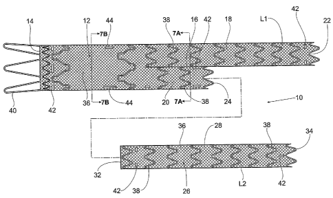
Fig. 1 is a side view of a multi-lumen prosthesis
assembly that embodies features of the invention, the
prosthesis assembly comprising two components prior to
assembly.
Fig. 2A is a side view of the multi-lumen prosthesis
assembly shown in Fig. 1 in an assembled condition.
Fig. 2B is an enlarged view of the multi-lumen
prosthesis assembly shown in Fig. 2A, showing the telescopic
fitment within the interface region between the extension
component and the second lumen of the main trunk.
Fig. 3 is a perspective view of the first component
of the multi-lumen prosthesis assembly shown in Fig. 1
CA 02546721 2006-03-22
WO 2005/044148
PCT/US2004/027590
- 4 -
positioned within an abdominal aortic aneurysm, with a
main trunk of the first component being located within
the aorta and a leg of the first component being located
in an iliac.
Fig. 4 is a perspective view of the first and second
components of the multi-lumen prosthesis assembly after
their assembly within an abdominal aortic aneurysm,
showing the first component being located within the
aorta, with one leg in an iliac, and the second component
being located telescopically within the first component
with a leg extending into a contralateral iliac.
Fig. 5 is a perspective view of an endovascular
graft delivery catheter carrying the first component of
the multi-lumen prosthesis assembly in a radially
compressed condition into a desired location within an
abdominal aortic aneurysm, the first component, upon
deployment by the catheter, radially expanding to the
condition shown in Fig. 3.
Fig. 6 is a perspective view of an endovascular
graft delivery catheter carrying the second component of
the multi-lumen prosthesis assembly in a radially
compressed condition into association with the previously
deployed first component, the second component, upon
deployment by the catheter, radially expanding to the
condition shown in Fig. 4.
Fig. 7A is a section view of the distal end of the
trunk component of the multi-lumen prosthesis assembly
taken generally along line 7A-7A of Fig. 1.
Fig. 7B is a section view of the proximal end of the
trunk component of the multi-lumen prosthesis assembly
taken generally along line 7B-7B of Fig. 1.
DETAILED DESCRIPTION OF THE INVENTION
I. Multi-Lumen Prosthesis Assembly
Fig. 1 shows a multi-lumen prosthesis assembly 10
CA 02546721 2006-03-22
WO 2005/044148
PCT/US2004/027590
- 5 -
that embodies features of the invention. In the
illustrated embodiment, the multi-lumen prosthesis
assembly 10 comprises a trunk component 12 and at least
one extension component 26.
The trunk component 12 is sized and configured to
fit within a hollow body organ and/or a blood vessel. As
described in this specification, the targeted site of
deployment is within the aorta adjacent the renal
arteries, as will be described in greater detail later.
However, this targeted site of deployment is selected for
purposes of illustrating the features of the assembly 10,
and is not intended to be limiting.
The trunk component 12 includes an interior
communicating with a proximal opening 14 for fluid flow
into or from the prosthesis. The trunk component 12
includes a septum 16 within its interior. The length of
the septum 16 within the prosthesis can vary. In the
illustrated embodiment, the septum 16 does not extend
along the entire length of the trunk component 12, but is
spaced a distance from the proximal opening 14. In the
illustrated arrangement, the septum 16 comprises a
longitudinal seam. The seam can be formed, e.g., by
sewing, heat bonding, or weaving opposing surfaces (i.e.,
the front and back) of the material 36 (which is
typically a fabric) of the trunk component 12 together,
thereby creating a septum or shared, common wall between
two lumens 18 and 20 (see Figs. 7A and 7B).
The septum 16 transforms at least a portion of the
interior of the trunk component 12 into a multi-lumen
flow channel configuration. In the illustrated
embodiment, the multi-lumen flow channel configuration
comprises dual first and second interior lumens 18 and
20. Due to the septum 16, the dual first and second
interior lumens 18 and 20 of the multi-lumen flow channel
configuration do not form branched or divergent legs (as
CA 02546721 2006-03-22
WO 2005/044148
PCT/US2004/027590
- 6 -
Figs. 7A and 7B show). The shared common wall (the septum
16) prevents divergence and maintains the lumens 18 and
20 in a non-divergent, generally parallel flow
relationship (as Figs. 7A and 7B show).
In the illustrated arrangement, the septum 16 runs
generally along the mid-line of the trunk component 12,
making the multi-lumen flow channel configuration within
the trunk component 12 essentially symmetric. However,
it should be appreciated that the septum 16 could form a
non-symmetric multi-lumen flow channel configuration. It
should also be appreciated that multiple septums can be
present within the interior, transforming the interior of
the trunk component 12 into a several flow lumens. The
length of the septum can vary. In a representative
embodiment, the septum is typically greater than 10 mm in
length and not less than 5 mm in length.
In the illustrated embodiment, the second lumen 20
is truncated along at least a portion of the septum 16.
As a result, the distal opening 22 of the first lumen 18
can be said to extend beyond the distal opening 24 of the
second lumen 20. Still, the shared common wall (the
septum 16) prevents divergence and maintains the lumens
18 and 20 in a non-divergent, generally parallel flow
relationship.
The first lumen 18 defines a flow channel sized and
configured to reach a targeted destination or source
spaced a defined distance from the proximal opening 14,
while the truncated second lumen 20 communicates with
generally the same targeted destination as the proximal
opening 14 of the trunk component 12 itself. Furthermore,
the septum 16 is sized and configured to accommodate the
coupling of a flow channel extension to the truncated
second lumen 20, to likewise extend its reach to another
targeted source or destination spaced from the distal
opening 24, if desired.
CA 02546721 2006-03-22
W02005/044148
PCT/US2004/027590
- 7 -
In this arrangement (see Fig. 2A), the multi-lumen
prosthesis assembly 10 includes a flow channel extension
component 26. The extension component 26 includes a
proximal end 32 that is sized and configured to be
telescopically fitted within the truncated second lumen
20 of the trunk component 12. The distal end 34 of the
extension component 26 is sized and configured to extend
the reach of the truncated second lumen 20 to another
targeted destination or source spaced a defined distance
from the proximal opening 14. As a result, a portion of
the extended second lumen 20 is joined to the first lumen
18 by the septum 16, and a portion of the extended second
lumen 20 is not joined by the septum 16 to the first
lumen 18.
The truncated second lumen 20 of the trunk component
12, which is joined by the septum 16 to the first lumen
18, provides an interface region or socket that, like the
second lumen 18, is fully enclosed within the body of the
trunk component 12 itself. The truncated second lumen 20
is therefore not prone to kinking or twisting or other
kinds of movement independent of the trunk component 12.
Passage of a guide wire through the second lumen 20 can
occur unimpeded.
Being telescopically fitted within the interface
region or socket and enclosed within the trunk component
12, the mechanical properties of the extension component
26 are supplemented by the structural support and
integrity of the trunk component 12 itself, and vice
versa. Coupled together, the trunk component 12 and the
extension component 26 provide enhanced resistance to
migration and/or separation of the extension component 26
from the trunk component 12. Seated within the enclosed
interface region, the extension component 26 is
peripherally sealed within the trunk component 12 to
resist leaks or seepage of fluids around the extension
CA 02546721 2006-03-22
W02005/044148
PCT/US2004/027590
- 8 -
component 26. The septum 16 can be tapered, curved,
wavy, or otherwise non-linear to enhance the connection
between the extension component and the trunk component
12.
In one illustrated use (see Fig. 3), the trunk
component 12 can be deployed in the aorta in the region
of the bifurcation of the first and second iliac. When
properly deployed, the first lumen 18 can be sized to
reach into the first iliac of the bifurcation, while the
second lumen 20 remains in communication with the aorta.
After the trunk component 12 is deployed (see Fig. 4),
the extension component 26 can be fitted within the
opening 24 of the second lumen 20, so that the distal end
34 of the second lumen 20 can reach into the second iliac
of the bifurcation. In this arrangement, the first lumen
18 serves as a first leg Ll of the prosthesis, and the
extension component 26 serves as a contralateral leg L2.
As described, both trunk and extension components 12
and 26 desirably 'utilize a prosthetic material 36
carrying individual self-expanding, zigzag type stent
rings 38. The stent rings 38 need not be attached to one
another throughout the prosthesis. However, it may be
desirable in certain locations within the prosthesis
structure to have attachments between the individual
stent rings 38 to provide stability and/or additional
radial support. As before
stated, the septum 16 is
formed by sewing, heat bonding, or weaving opposing
surfaces (i.e., the front and back) of the prosthetic
material 36 of the trunk component 12 together. In the
region of the septum 16, the stent rings 38 extend from
the septum 16 about the formed lumen, but do not enter or
otherwise interrupt the septum 16 itself. The septum 16
is continuous and is formed separate from the supporting
structure of stent rings 38.
The individual stent rings 38 allow for longitudinal
=
CA 02546721 2006-03-22
W02005/044148
PCT/US2004/027590
- 9 -
prosthesis compliance while maintaining radial support of
the prosthesis lumens. This technical features allows the
prosthesis to more readily accommodate changes in
vessel/aneurysm morphology.
The stent rings 38 can be made, e.g., from Nitinol
wire. Still, other materials, manufacturing methods and
designs can be used., Each of the stent rings 38 is sewn
onto prosthetic material 36. In certain locations it is
desired to have the stent rings 38 attached to the outer
diameter of the prosthetic material 36. Still, it is also
contemplated that the stent rings 38 could be attached to
the inner diameter of the prosthetic material 36.
In the illustrated embodiment, the prosthetic
material 36 is woven polyester, and the attachment of the
stent rings 38 is made with polyester suture. However, it
is also contemplated that other attachment means could be
utilized to secure the stent rings 38 to the prosthetic
material 36. These means include bonding; capturing the
stent rings 38 between two layers of prosthetic material
36; and incorporating the stent rings 38 directly into
the woven prosthetic material 36.
The trunk component 12 may include a supra-renal
stent 40 at its proximal end, which extends beyond the
prosthetic material 36. When deployed within the aorta,
this stent would extend above the level of the renal
arteries. The supra-renal stent orients the prosthesis
within the lumen and aids in maintaining the position of
the prosthesis in the aorta without obstructing the
normal blood flow into the renal arteries.
In the trunk component 12, the proximal end of the
prosthesis (distal to the supra-renal stent 40) typically
has one or more stent rings 38. The purpose of the stent
rings 38 is to provide a seal between the vessel wall and
the graft so that blood does not flow outside of the
prosthesis and to help maintain the position of the
= CA 02546721 2012-08-01
69790-88
- 10 -
prost he s i s in the aorta. Typically, this region of the
aorta (proximal neck of the aneurysm just below the
renal arteries) is also where one or more fasteners may
desirably be introduced by a fastener attachment
assembly to anchor the prosthesis in place.
Further details of the fastener attachment assembly
can be found in United States Patent 8,075,570. It
is desirable that this region of the trunk
component 12 be sized and configured for the receipt and
retention of fasteners, e.g., the size and spacing of
ring stent patterns to specially accommodate the
placement of fasteners; and/or the use of woven fibers
with an "X-pattern" or a "sinusoidal pattern" to
specially accommodate placement of fasteners; and/or to
fold over the prosthetic material to form multiple
layers, to reinforce the prosthesis in the region where
fasteners are placed; and/or the use of denser weave
patters or stronger fibers from, e.g., Kevlar material
or Vectran' material or metallic wire woven alone or
interwoven with typical polyester fibers in the region
were fasteners are placed. It may also be desirable to
fluoroscopically indicate this region of the prosthesis
with radiopaque markers 42 on the prosthetic material 36
or stent rings 38 to aid in positioning the fastening
staples.
Additional stent rings 38 may be utilized throughout
the main trunk of the first component 12. Desirably, a
minimal number of stent rings 38 would be utilized within
the trunk component 12. Typically, however, a stent ring
36 would be attached just proximal to the longitudinal
seam 16 in the main trunk.
The longitudinal seam 16 in the main trunk can be
created by methods such as sewing, heat bonding, or
possibly weaving the front and the back of the prosthetic
CA 02546721 2006-03-22
WO 2005/044148
PCT/US2004/027590
- 11 -
material 36 together. Typically the seam 16 would be
located along the midline of the main trunk to create two
equally sized lumens 18 and 20. However, the location of
the seam 16 could be moved, if different sized lumens
were desired.
The multiple lumens 18 and 20 in the trunk component
12 may typically be supported with stent rings 38 on the
inside of the prosthetic material 36. Ideally, the stent
rings 38 in one lumen 18 are staggered in position with
the stent rings 38 in the other lumen 20, so that they do
not overlap each other when the first component 12 is
radially compressed prior to deployment. Typically, stent
rings 38 would be attached to the outside of the first
lumen 18 of the trunk component 12.
Rotational orientation of the trunk component 12
within the vessel lumen or hollow body organ is
accomplished with additional radiopaque markers 44
attached to the prosthesis for visualization under
fluoroscopy. Typically, these markers 44 may be attached
to the prosthetic material 36. Still, the markers 44 may
be attached to stent rings 38 instead of or in addition
to the prosthetic material 36. The radiopaque markers 44
typically are in the form of marker bands, tight wound
coils, or wire made from radiopaque materials such as
platinum, platinum/iridium, or gold. The radiopaque
markers 44 may be attached to the prosthetic material 36
or stent rings 38 to help fluoroscopically determine the
location of all prosthesis openings and to indicate the
insertion depth for the extension component 26 into the
second lumen 20 of the trunk component 12. Desirably, two
markers 44, one longer than the other, are attached on
opposite sides of the main trunk of the first component
12 with the longer marker aligned on the side with the
leg L1. The two markers 44 enable the user to determine
the proper rotational orientation of the prosthesis in
=
CA 02546721 2006-03-22
W02005/044148
PCT/US2004/027590
- 12 -
the delivery system so that, upon deployment, the second
distal opening 20 is aligned with the contralateral iliac
artery.
The extension component 26 has stent rings 38
attached to the outside of prosthetic material 36 along
its entire length, with some spacing between the stent
rings 38. However, as in the trunk component 12, it is
contemplated that the stent rings 38 could also be placed
on the inside of the prosthetic material 36. Furthermore,
as previously discussed, the stent rings 38 need not be
attached to one another throughout the prosthesis.
However, it may be desirable in certain locations within
the prosthesis structure to have attachments between the
individual stent rings 38 to provide stability and/or
additional radial support. The addition of the stent
rings 38 to the extension component 26 aids in the
deployment of the extension component 26 and allows for
longitudinal compliance while maintaining radial support
of the lumen within the extension component 26.
Typically, radiopaque markers 42 are used on each end of
the prosthesis to aid in the visualization of the
placement of the extension component 26 within the lumen
of the second distal opening 24 of the first component
12.
As shown in Figs. 2A and 2B, the stent rings 38 in
the extension component 26 can be sized, configured, and
arranged to engage the stent rings 38 in the second lumen
20 of the main trunk 12. This engagement prevents the
extension component 26 from moving or migrating
longitudinally in relating to the second lumen 20 after
the extension component 26 has been deployed.
II. Use of the Multilumen Prosthesis Assembly
During use (see Fig. 5), a first catheter 46 is
navigated over a guide wire 48 through an iliac to the
desired location within the aorta near the renal
CA 02546721 2006-03-22
WO 2005/044148
PCT/US2004/027590
- 13 -
arteries. The catheter 46 carries the trunk component 12
of the multi-lumen prosthesis system 10 in a radially
reduced configuration. At the targeted site, the catheter
46 releases the trunk component 12, which expands
radially into the position shown in Fig. 3.
As Fig. 6 shows, the extension component 26 is
carried in a radially compressed condition by another
over-the-wire catheter 50 coming from the contralateral
iliac. The catheter 50 deploys the extension component
26, such that the proximal end of the extension component
26 is telescopically received within the second lumen 20
of the trunk component 12 and the distal end extends into
the contralateral iliac, as Fig. 4 shows. Only when the
extension component 26 is telescopically received within
the second lumen 20 of the trunk component 12, a
bifurcated prosthesis is formed with divergent legs.
The preferred embodiments of the invention are
described above in detail for the purpose of setting
forth a complete disclosure and for the sake of
explanation and clarity. Those skilled in the art will
envision other modifications within the scope and sprit
of the present disclosure.
The above described embodiments of this invention
are merely descriptive of its principles and are not to
be limited. The scope.of this invention instead shall be
determined from the scope of the following claims,
including their equivalents.