Note: Descriptions are shown in the official language in which they were submitted.
CA 02546758 2006-05-12
A SYSTEM AND A METHOD FOR DETECTING
A DAMAGED OR MISSING MACHINE PART
TECHNICAL FIELD
A system and a method for detecting a damaged or missing machine part using
image analysis and computer vision techniques.
BACKGROUND OF THE INVENTION
Various technologies have been proposed for inspecting machines and/or
detecting and reporting incidences of damage to machine parts.
Japan Patent Application No. 07257561 (Fumiaki et al) describes a method for
detecting a wrong or missing engine part which involves capturing images using
a CCD camera
and comparing detection data with reference data based upon the brightness
distribution within
regions of the captured images.
United States Patent No. 4,399,554 (Perkins, III et al) describes a system for
inspecting engine head valve spring assemblies for missing retainer keys which
comprises a
solid state camera for taking pictures of a valve spring assembly and
providing picture data, a
position encoder which relates the position of the engine head to the camera,
and a computer
which analyzes the picture data to determine the center of a digitized image
of a valve spring
assembly and an intensity profile of the expected location of the retainer
keys relative to the
center of the valve spring assembly, which intensity profile is used to
determine whether a
retainer key is missing.
United States Patent No. 5,743,031 (Launder et al) describes an apparatus for
providing a signal indicative of loss or imminent loss of digging hardware.
The apparatus
includes an actuatable indicator and an actuator. In the preferred embodiments
the actuator is
comprised of a lanyard which is secured between an adaptor and a digging
tooth. If the digging
-1-
CA 02546758 2006-05-12
tooth breaks off or becomes dislodged from the adaptor, the lanyard senses the
change in
predetermined relationship between the adaptor and the digging tooth and
actuates the
actuatable indicator. In the preferred embodiments the actuatable indicator is
comprised of a
smoke canister.
United States Patent No. 6,796,709 (Choi) describes a method and system for
estimating turbine bucket oxidation condition. The method includes measuring
with an infrared
camera a temperature distribution on a surface of a rotating turbine bucket,
determining a
condition index based upon the temperature distribution, and estimating the
turbine bucket
oxidation condition based on the condition index. The system includes the
infrared camera, a
triggering mechanism coupled with the infrared camera for triggering the
camera at
predetermined intervals based upon the rotating speed of the turbine, and a
processor for
receiving the output from the infrared camera and for determining the
condition index.
U.S. Patent No. 6,870,485 (Lujan et al) describes a method and apparatus for
detecting and reporting dislocation of heavy metal parts on mining equipment.
The apparatus
includes a spring loaded switch sandwiched between heavy metal parts, which
upon partial
separation of the parts expands and turns on an electrical switch to activate
a radio transmitter,
sending an alarm signal to a receiver at a remote location.
United States Patent Application Publication No. US 2005/0081410 Al (Furem
et al) describes a system and method for distributed reporting of machine
performance. The
system is comprised of a machine data management system which permits
information relating
to a machine to be gathered and analyzed while the machine is operating.
Another technology proposed by the University of Alberta (Xiujuan Luo) uses
laser range data for detecting missing shovel teeth. The technology involves
creating a CAD
model of an intact tooth, using a laser range finder to scan the tooth line of
a shovel, and
comparing the laser scan with the CAD model to detect missing teeth.
-2-
CA 02546758 2006-05-12
Finally, Motion Metrics International Corp. of Vancouver, British Columbia
offers a broken tooth detection system for mining shovels and loaders under
the trade-mark
ToothMetrics Tn''
SUMMARY OF THE INVENTION
The present invention is a system and a method for detecting a damaged or
missing machine part. The invention may also be comprised of a computer which
is
programmed to perform aspects of the method. The invention may also be
comprised of a
computer readable medium which contains computer readable instructions for
performing
aspects of the method. The invention may also be comprised of a signal which
is operable to
cause a processor to perform aspects of the method.
The machine may be any type of machine and the machine part may be
comprised of any type of part associated with the machine.
In a first broad system aspect, the invention is comprised of:
(a) an image capturing device such as a camera, for capturing images of a
machine
against a background which moves relative to the machine over time; and
(b) a processor for processing the captured images to determine whether one or
more machine parts is damaged or missing.
In preferred embodiments of the invention, the machine is a mining shovel and
the machine part is a tooth on the bucket of the shovel.
In a second system aspect, the invention is comprised of:
-3-
CA 02546758 2006-05-12
(a) an image capturing device such as a camera, for capturing images of a
bucket
tooth line against a background which moves relative to the bucket over time;
and
(b) a processor for processing the captured images to determine whether one or
more teeth on the bucket is damaged or missing.
The processor is preferably programmed to perform aspects of the method of the
invention.
The system of the invention may also be comprised of a sensible output for
providing an indication of a damaged or missing tooth. The sensible output may
be comprised
of a visual display, an audible alarm, or any other type of output which may
be sensed by a
person or apparatus. For example, the sensible output may be comprised of a
signal which
causes the mining shovel to stop operating when a damaged or missing tooth is
detected.
The image capturing device is preferably mounted on the mining shovel so that
a
clear image of the bucket tooth line may be obtained at some point during the
operation of the
mining shovel as a load is taken up by the mining shovel, moved to an
unloading position and
then dumped at the unloading position. Preferably the image capturing device
is mounted on
the mining shovel so that a clear image of the bucket tooth line may be
obtained immediately
after the load is dumped at the unloading position.
The processor may be located at any suitable position on or within the mining
shovel. The processor may alternatively be located remotely of the mining
shovel. A
communication link is provided between the image capturing device and the
processor so that
the captured images may be provided to the processor for processing. The
communication link
may be comprised of any suitable type of link, including wired communication
links and
wireless communication links.
In a first broad method aspect, the invention is comprised of:
-4-
CA 02546758 2006-05-12
(a) capturing images of a machine against a background which moves relative to
the
machine over time;
(b) selecting two time-separated images which reflect movement of the
background
relative to the machine;
(c) generating a displacement image from the two time-separated images,
wherein
the displacement image provides an indication of movement of each pixel
represented in the displacement image between the two time-separated images;
(d) comparing the machine from the displacement image with a model machine;
and
(e) identifying a damaged or missing machine part from the comparison of the
machine from the displacement image and the model machine.
The second method aspect may be further comprised of providing a sensible
output which indicates a damaged or missing machine part.
In preferred embodiments the method of the invention involves the capturing of
at least two images of a mining shovel bucket with an image capturing device
such as a camera,
while the mining shovel is operating. For example, if two images are captured
at different
times while the mining shovel is operating, the apparent movement of pixels
representing the
bucket and the apparent movement of pixels representing the background of the
image will be
different, as long as the bucket moves relative to the background during the
time between the
capturing of the two images. The difference in movement can be used to
determine which
pixels in the images represent the bucket and which pixels in the image
represent the
background. More particularly, a displacement image may be generated from the
two images,
which displacement image will provide an indication of which pixels have
"moved" between
the two images and which images have not moved between the two images.
-5-
CA 02546758 2006-05-12
In a second method aspect, the invention is comprised of:
(a) capturing images of the bucket tooth line against a background which moves
relative to the bucket over time;
(b) selecting two time-separated images which reflect movement of the
background
relative to the bucket;
(c) generating a displacement image from the two time-separated images,
wherein
the displacement image provides an indication of movement of each pixel
represented in the displacement image between the two time-separated images;
(d) comparing the bucket tooth line from the displacement image with a model
bucket tooth line; and
(e) identifying a damaged or missing tooth from the comparison of the bucket
tooth
line from the displacement image and the model bucket tooth line.
The second method aspect may be further comprised of providing a sensible
output which indicates a damaged or missing tooth.
In a third method aspect, the invention is comprised of:
(a) capturing a number of time-separated images of a bucket tooth line against
a
background which moves relative to the bucket over time;
(b) initial processing one or more pairs of the captured images to select a
suitable
pair of images from the gathered images, having regard to one or more of the
following:
-6-
CA 02546758 2006-05-12
(i) whether the bucket tooth line can be adequately identified in the pair of
images (the bucket is not completely fixed relative to the image capturing
device, but may raise and lower relative to the image capturing device
and may move toward or away from the image capturing device. As a
result, the bucket tooth line is adequately identified in the pair of images
when it is within a defined position zone of the image and has a size in
the image which is within a defined size range);
(ii) whether the background is moving relative to the image capturing device
and the bucket tooth line (since the method of the invention requires the
generation of displacement images, the method will not work if there is
no movement of the background relative to the image capturing device
and the bucket tooth line); and
(iii) whether the magnitude of the relative movement of the background
between two images in a pair of images is within a desired range (too
little movement reduces the resolution of the method and too much
movement taxes the processing capabilities of the system by requiring a
larger area of the images to be processed);
(c) final processing the suitable pair of images to generate a displacement
image
from the suitable pair of images, wherein the displacement image provides an
indication of movement of each pixel represented in the displacement image
between the two images in the suitable pair of images;
(d) comparing the bucket tooth line from the displacement image with a model
bucket tooth line; and
(e) identifying a damaged or missing tooth from the comparison of the bucket
tooth
line from the displacement image and the model bucket tooth line.
-7-
CA 02546758 2006-05-12
The third method aspect may be further comprised of providing a sensible
output
which indicates a damaged or missing tooth.
In a fourth method aspect, the invention is comprised of:
(a) capturing a sequence of images using an image capturing device such as a
video
camera;
(b) initial processing one or more pairs of the captured images to select a
suitable
pair of images from the gathered images;
(c) generating a displacement image from the suitable pair of images, wherein
the
displacement image provides an indication of movement of each pixel
represented in the displacement image between the two images in the suitable
pair of images;
(d) locating a first boundary of the bucket in the displacement image;
(e) locating a second boundary of the bucket in the displacement image;
(f) creating a model bucket tooth line using the coordinates of the first
boundary
and the second boundary;
(g) comparing the bucket tooth line from the displacement image with the model
bucket tooth line; and
(h) identifying a damaged or missing tooth from the comparison of the bucket
tooth
line from the displacement image and the model bucket tooth line.
The fourth method aspect may be further comprised of providing a sensible
output which indicates a damaged or missing tooth.
-8-
CA 02546758 2006-05-12
The processing of images, including the initial processing, the final
processing,
and comparing the bucket tooth line from the displacement image with the model
bucket tooth
line, may be performed using any suitable computer vision, image motion,
optical flow, image
matching or pattern matching method. For example, the processing of pairs of
images may be
performed using techniques used in stereo matching. The processing of images
is preferably
performed using a computer which is directed by computer codes to perform
aspects of the
method.
In preferred embodiments, the processing of images is performed using pattern
matching or block matching methods. Such pattern matching or block matching
methods may
include various matching criteria and/or search strategies. As non-limiting
examples, matching
criteria may include maximum cross-correlation, minimum mean square error,
minimum mean
absolute difference and maximum matching pixel count methods. As non-limiting
examples,
search strategies may include three step search or cross search methods.
Pattern matching or block matching methods which are suitable for use in some
or all aspects of the method of the invention may be embodied in commercially
available
software or may be performed using custom applications.
As an example of commercially available software, Matrox Imaging, a division
of Matrox Electronic Systems Ltd. of Dorval, Quebec has developed the Matrox
Imaging
Library (MIL) as a development kit for pattern matching and block matching
software
solutions. One or more modules within the MIL may be used for aspects of the
method of the
invention.
The generation of displacement images from captured images may similarly be
performed using commercially available software, or may be performed using
custom
application for the generation of the displacement images.
-9-
CA 02546758 2006-05-12
In the preferred embodiments of the invention, the processing of the images,
including pattern matching/block matching and the generation of displacement
images from
pairs of images, is performed using a combination of commercially available
software and
custom applications which both apply methods known in the art of image
processing.
The initial processing of pairs of images may be performed in a manner which
minimizes the initial processing time. The initial processing time may be
minimized using
techniques known in the art, by specifying processing parameters and by
defining search
constraints. However, the initial processing of images is preferably performed
using a
relatively large area of the images, since one of the goals of the initial
processing is to
determine the magnitude of the relative movement of pixels in the pair of
images in order to
assess the suitability of the pair of images for final processing.
The final processing of pairs of images is preferably performed in a manner
which balances the required accuracy of the method with the required speed of
the method. As
a result of the initial processing, the final processing in many applications
may be performed
using a relatively small area of the images, since the expected position of
the pixels in the two
images will to some extent be known.
BRIEF DESCRIPTION OF DRAWINGS
Embodiments of the invention will now be described with reference to the
accompanying drawings, in which:
Figure 1 is a block diagram of a system for detecting a damaged or missing
tooth
on a mining shovel, according to a preferred embodiment of the invention.
Figure 2 is a view of a touch screen monitor according to a preferred
embodiment of the invention upon the detection of a damaged or missing bucket
tooth.
-10-
CA 02546758 2006-05-12
Figure 3 is a view of a touch screen monitor according to a preferred
embodiment of the invention following the touching of the "Acknowledge" button
in the view
of Figure 2.
Figure 4 is a first captured image in a sequence of captured images.
Figure 5 is a second captured image in a sequence of captured images.
Figure 6 is a displacement image generated from the captured images from
Figure 1 and Figure 2.
Figure 7 is a model of an upper left corner of a bucket, representing a first
boundary of the bucket.
Figure 8 is a schematic drawing depicting the displacement image of Figure 3
with the model of Figure 4 superimposed thereon.
Figure 9 is a model of an upper right corner of a bucket, representing a
second
boundary of the bucket.
Figure 10 is a schematic drawing depicting the displacement image of Figure 3
with the model of Figure 6 superimposed thereon.
Figure 11 is a model bucket tooth line created using the coordinates of the
first
boundary of the bucket and the second boundary of the bucket.
Figure 12 is a schematic drawing depicting the displacement image of Figure 3
with the model bucket tooth line superimposed thereon.
-11-
CA 02546758 2006-05-12
DETAILED DESCRIPTION
Determining the presence or absence of a tooth on a mining shovel by
inspection
of a single image taken by a camera is difficult. If two time-separated images
of the bucket of
the mining shovel are captured while the mining shovel is being operated, the
apparent
movement of background pixels and bucket pixels (i.e., foreground) can be
different. This
difference in movement can be used to determine which pixels in the captured
images are part
of the bucket (foreground) and which pixels are part of the background.
The present invention is a remote 'machine vision' technology, which in the
preferred embodiments utilizes video camera output and specialized computer
algorithms to
monitor bucket teeth on a mining shovel.
The bucket tooth line of the bucket is analyzed on each upswing of the mining
shovel and compared against a base-case scenario of a fully intact tooth line.
When a tooth is
partially or completely broken or missing, the system automatically alerts the
shovel operator
by a sensible output in the form of a visual alarm on a touch screen monitor.
With the system of the invention, shovel operators are alerted to partial or
complete tooth breakage as soon as the shovel comes into the viewing range of
the camera.
The invention offers the following benefits to a mine site:
(a) prevents broken bucket teeth from damaging the crusher, conveyer belts,
screens,
pumps and other expensive equipment;
(b) minimizes downtime by detecting broken teeth at the time of the breakage
incident; and
(c) improves overall efficiency in the mining operation through constant
monitoring
of the bucket tooth line status in terms of teeth wear.
-12-
CA 02546758 2006-05-12
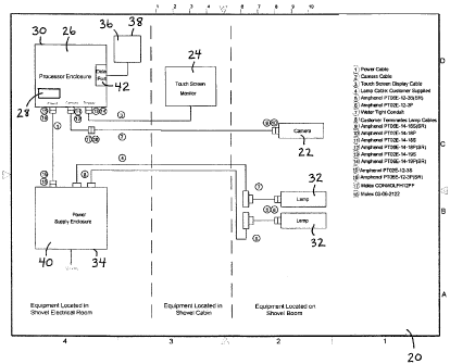
In the preferred embodiment, the system (20) of the invention comprises a
number of components that make up the hardware and provide the software which
includes the
algorithms for system operation.
The features of the preferred embodiment of the system (20) can be summarized
as follows:
(a) industrial-grade components, no moving parts, rugged construction;
(b) a lightweight, vibration resistant video camera (22) as an image capturing
device, designed for rugged outdoor operation, combined with a sun shroud for
protection;
(c) a compact (10.4") rugged LCD monitor (24) with resistive touch screen
display.
When a missing tooth is detected, the operator can both check the sensible
output (i.e., visual alarm) and inspect a real time image of the bucket tooth
line;
(d) fully molded connectors designed for rugged application, combined with
cable
wiring that is resistant to severe weather conditions and rugged shovel
operations;
(e) PC 104 computing hardware (26) with a Windows XP embedded operating
system;
(f) software providing image matching/pattern matching algorithms, which
software
resides on a computer readable medium such as a compact flash card (28) which
inserts into the processor (26);
(g) NEMA IV enclosures to protect the components of the system (20).
-13-
CA 02546758 2006-05-12
A block diagram of the components of the system (20), according to a preferred
embodiment of the invention, is provided as Figure 1.
Referring to Figure 1, the following provides a description of the components
of
the system (20).
The camera (22) is provided by Kongsberg from Scotland. The required field of
view for each shovel application is determined and the required field of view
is provided for in
the camera (22).
The central processing unit (CPU) (26) processor enclosure (30) is designed in
accordance with NEMA IV specifications and incorporates Mil-Spec connectors.
This
processor enclosure (30), which is sealed and weatherproof, should be placed
in the shovel
instrument room (not shown).
The high intensity discharge (HID) lamps (32) are model number Hella
AS200FF Xenon HID lamps, manufactured by Hella KGaA Hueck & Co.
The power systems are designed in accordance with the user's specifications.
In
the preferred embodiments, 120 Volt AC is provided to the system (20). Power
is converted to
12 or 24 Volt DC for the lamps (32), the monitor (24) and the CPU (26). The
lamp (32) power
is supplied directly from the power supply enclosure (34). Power for the
camera (22) and the
monitor (24) is supplied through the processor enclosure (30) via cables that
supply electrical
power and transmit image capture (camera) and touch screen controls (touch
screen monitor).
An optional data storage device (36) (preferably a +200 Gigabyte portable hard
drive) may be included. This extended data logging capability facilitates
troubleshooting and
resolution of any site-specific issues that may arise in the course of
installing and using the
system. Where a data storage device (36) is provided, a separate data storage
device enclosure
(38) may be provided for this component.
-14-
CA 02546758 2006-05-12
The user interface is preferably an industrial touch screen monitor (24).
The processor (26), power supply elements and optional data storage device
(36)
are preferably placed in separate NEMA IV enclosures that may be placed in an
electrical room
on the mining shovel (not shown).
The processor enclosure (30) contains the processing hardware (26) and the
power supply (40) for the camera (22) and touch screen monitor (24). From this
enclosure, the
camera (22) and monitor (24) are powered. There are three Mil-Spec connectors
on the bottom
of the processor enclosure (30) for DC Power in, a cable for the touch screen
monitor (24), and
the cables for the camera (22). A data port (42) is also located on the
processor enclosure (30),
which data port (42) includes a USB connector and a network connector. The USB
connector
can be used by the data storage device (36) or by a USB memory stick, for
downloading data.
The network connection can be used by a laptop computer for diagnostic
purposes.
The operating system of the processor (26) utilizes a Windows-XP embedded
system which has been designed to reliably handle power interruptions without
corrupting or
hanging up the processor (26). The processor (26) boots when power is present
and flicking
power off/on at any time during shovel operations is acceptable.
The processing software is stored on a computer readable medium such as a
compact flash card (28) which inserts into the processing hardware (26).
Details of the
methods and algorithms which are included in the processing software are
provided below in
connection with the description of a preferred embodiment of the method of the
invention.
The power supply enclosure (34) contains the elements that connect to the 120
Volt AC input provided on the mining shovel. 120 Volt AC is run into the power
supply
enclosure (34) and connected to the terminals. The connection must be a sealed
connection to
ensure conformance to NEMA IV specifications. In the preferred embodiment the
120 Volt AC
power is converted and provided to the power inlet of the processor enclosure
(30) as 24V DC.
- 15 -
CA 02546758 2006-05-12
Power for the lamps (32) is provided from the power supply enclosure (34)
directly to the lamps (32) as 24 Volt DC. A feature provided in the power
supply enclosure
(34) is a time-delay relay which turns on lamps sequentially in order to avoid
excessive power
draw on start-up (the lamps require 10 Amps each to start, but normal current
usage is 1.6
Amps for each lamp).
The data storage device enclosure (38) contains the data storage device (36)
and
is preferably installed in the electrical room of the mining shovel.
The image capturing device (22) is preferably a high resolution monochrome
video camera Model 0414-6002-002, manufactured by Kongsberg.
The lamps (32) are 35 watts and require 24 Volt DC power. Preferably two (2)
lamps (32) are used to illuminate the bucket. The lamps (32) are resistant to
mechanical
vibration and shock, but care must be exercised when the lamps (32) are in use
or being
transported.
The camera (22) and the lamps (32) are preferably placed separately on the
shovel boom (not shown).
The camera mounting bracket preferably can be loosened to allow altering the
camera pan position. Preferably both the camera (22) and lamps (32) are
capable of both
panning and tilting movement.
The lamp power cable or cables are preferably Tech Cable #14, armoured PVC
cable. Conduit Tee LB junction units are preferably provided for each lamp
(32) to allow
connection of the lamp power cable to the two lamps (32). This conduit Tee is
weatherproof
and is designed for rugged applications and is preferably placed on the lamp
mount.
A compact (10.4"), rugged, flat panel LCD monitor (24), with resistive touch
screen, is preferably provided as the operator interface. This monitor (24) is
preferably placed
-16-
CA 02546758 2006-05-12
in the cab of the mining shovel within reach of the shovel operator. The
monitor (24) is
connected to the processor enclosure (30) via a single cable. This cable
provides the power,
VGA signal, and touch screen communications. The screen of the monitor (24)
provides an
image of the bucket and a visible alarm in the event of detection of damaged,
broken or missing
teeth. The interface is designed to show initially a yellow dot on a specific
tooth location where
there might be damage or significant wear. A red dot will appear if a full
tooth missing.
The preferred monitor (24) is a model LMV 10 provided by Datalux. Details of
the specifications of the preferred monitor (24) can be found at
www.datalux.com.
Mil-Spec cable connectors using adhesive heat shrink are preferably provided
for
all cables in order to provide weather protection.
The camera cables are preferably provided by Intec Video Systems. The main
function of the cable jackets is to protect the primary insulation from
environmental damage.
The Intec Video Systems cables have polyurethane cable jackets that offer high
performance
and durability by providing long-lasting protection in applications requiring
low-temperature
flexibility, good weathering properties and resistance to wet environments.
Polyurethane consistently outperforms conventional rubber compounds; its
abrasion resistance makes polyurethane superior to copolyester and
thermoplastic polyolefins,
and it also offers superior protection from physical damage. Polyurethane
cable jackets are also
excellent for applications over a wide range of temperatures. Over extended
use, polyurethane
continues to protect the inner components of assemblies at temperatures up to
50 C, as well as
offering low temperature flexibility to -40 C.
A 3-conductor power connector cable, designed for outdoor and low temperature
(-70 C) applications, is preferably used to connect the power supply enclosure
(34) to the
processor enclosure (30).
-17-
CA 02546758 2006-05-12
The main lamp power cables are preferably armour coated #14 tech PVC cables.
Figure 1 depicts two cables connecting the lamps (32) to the power supply
enclosure (34). In
practice, two cables with two conductors each, or one cable with four
conductors may be used
to provide the lamp power cables.
Connection cables are required from both LB Junction Conduit Tees to the
lamps (32), which cables are preferably the same type of cable as the power
connector cable
described previously.
A standard VGA cable is required for the touch screen monitor (24). This cable
provides power, a VGA signal, and touch screen communications. This cable is
connected to
the processor enclosure (30).
A standard USB cable may be used to connect the data storage device (36) to
the
data port (42) on the processor enclosure (30).
The following provides a description of the installation of the system (20) on
a
mining shovel.
The camera mount is installed on the shovel boom and preferably has an
adjustment bracket that allows the camera (22) to move both horizontally and
vertically for
achieving proper image capture. The lamps (32) are also mounted on the shovel
boom.
The cable connections along the shovel boom should be connected to ensure
secure fastening during rugged operations.
The touch screen monitor (24) is preferably placed in the main cab of the
mining
shovel, within reach of the operator and is connected using the touch screen
monitor cable. The
length of the touch screen monitor cable is preferably limited to 25 feet in
order to maintain
vision quality on the screen.
- 18 -
CA 02546758 2006-05-12
The system enclosures (30,34,38) are designed for placement in the electrical
room of the mining shovel. They are preferably fastened to the wall using
mounting kits. The
enclosures (30,34,38) are preferably sized as follows:
(a) the power supply enclosure (34) preferably has nominal dimensions of about
20"
x 16" x 6";
(b) the processor enclosure (30) preferably has nominal dimensions of about
12" x
12" x 6";
(c) the data storage device enclosure (38) (where provided) preferably has
nominal
dimensions of about 12" x 10" x 4".
A 120 Volt AC power line and the lamp cable(s) are connected to the power
supply enclosure (34). In the preferred embodiments the lamp cable(s) must be
capable of
handling up to 12 amps of current.
The following provides a description of the procedure for starting up and
operating the system (20).
Once all of the power supply enclosure (34), the processor enclosure (30), the
data storage device enclosure (38), the monitor (24), the cable connections,
the camera (22) and
the lamps (32) are installed and connected, the system power supply (40) may
be turned on,
which causes the processor (26) to "boot up". Once the processor (26) has
booted up, the
screen of the monitor (24) will display a full image from the camera (22).
The orientation of the camera (22) is important for the optimal functioning of
the
system (20). The better the orientation of the camera (22), the better the
image capture in all
conditions. The following steps are recommended for setting up the camera (22)
and for
subsequent image capture:
-19-
CA 02546758 2006-05-12
(a) the bucket should be positioned on the ground in order to begin the
orientation of
the camera (22);
(b) the camera (22) "pan" should be adjusted to center the bucket (48) in the
monitor
screen horizontally;
(c) The camera (22) "tilt" should then be adjusted so that the top half of the
bucket
(48) is visible on the monitor screen;
(d) the camera (22) and the lamps (32) may be adjusted as described
previously;
(e) the "rotation" of the camera (22) should be adjusted so that the camera
(22) is
rotated just slightly off the horizontal in the clockwise direction; and
(f) all bolts should be checked to ensure that they are tightened. If bolts
are
tightened, the orientation of the camera (22) should be re-checked to ensure
that
the camera orientation has remained the same after tightening (the rotation of
the
camera (22) is particularly important). If necessary, the camera (22) should
be
loosened and re-adjusted if tightening the bolts changes the position of the
camera (22).
With proper camera (22) orientation, the image that should appear is similar
to
the images in Figure 4 and Figure 5. The image includes the bucket (48) and
the teeth (50)
which are located on the bucket (48).
During operation of the system (20) the image stays full until a missing tooth
incident occurs. When a missing tooth incident is detected, the screen of the
monitor (24)
changes automatically to the image shown in Figure 11, and a yellow or red dot
will appear in
one or more of the tooth indicators.
-20-
CA 02546758 2006-05-12
If the operator then touches the "Acknowledge" button, the screen changes
automatically to the image shown in Figure 12. In this view, the operator may
touch the left tab
( ) or the right tab (>>) buttons in order to view previous or subsequent
images of the bucket
(48), and thus determine when the tooth or teeth (50) became broken or missing
(eg. during
loading or the bucket (48) or unloading of the bucket (48)).
The following provides an example of a preferred embodiment of the method of
the invention, described with reference to Figures 4-12:
1. capture a continuous sequence of images using the video camera (22). For
best
results, images should be captured at a frame rate of at least 60 frames per
second and a set of a minimum of 5 images should be captured. The speed of
image capture which provides good results is a function of the camera
resolution
and the apparent velocity of the background and foreground. For best results
the
frame rate and resolution of the camera (22) and the number of images captured
should be chosen so that the pixels comprising the background or the pixels
comprising the foreground have moved on average a distance of 4 pixels when
comparing 2 images out of the set of images. Increasing the number of images
in a set of captured images improves the chance of finding a suitable pair of
images if the background or foreground are moving slowly relative to each
other.
Increasing the image capture rate increases the chance of finding a suitable
pair
of images if the background and foreground are moving rapidly relative to each
other. Reducing the camera resolution reduces the processing time required.
Increasing the camera resolution increases the sensitivity of the system for
detecting damaged or missing teeth (50). Good results have been achieved with
an image resolution of 640x240 pixels, a capture rate of 60 images per second,
a
dataset comprising a sequence of 5 images, and an average movement of 4
pixels;
2, select a suitable pair of images based upon the criteria outlined above. A
suitable pair of images is depicted as Figure 4 and Figure 5;
-21 -
CA 02546758 2006-05-12
3. using a suitable pattern matching algorithm (for example, a"sum of absolute
differences" method) determine how far each pixel has moved during the time
between when the images of Figure 4 and Figure 5 were captured. Convert the
distance moved by each pixel to an 8 bit grayscale image having a pixel
intensity
from 0 to 255 to create a displacement image as shown in Figure 6. In order to
minimize the processing time involved 2 images should be selected so that the
maximum difference in movement of the foreground pixels relative to the
background pixels is about 7 pixels. In order to maximize the difference or
contrast between the foreground and background in the displacement image the
pair of images should be selected so that minimum difference in movement of
the foreground pixels relative to the background pixels is about 3 pixels;
4. using a pattern matching algorithm (for instance the MatroxTM pattern
matching
function) find the top left corner of the bucket (48) (i.e., the foreground)
in the
displacement image of Figure 6 as a first boundary of the bucket (48). This is
done by creating a model representative of the general shape of the top left
corner of the bucket (48) in the displacement image, as shown in Figure 7. The
pattern matching algorithm is used to find the best location of the model of
Figure 7 in the displacement image of Figure 6, which best location is
depicted
schematically in Figure 8;
5. using a pattern matching algorithm (for instance the MatroxTM pattern
matching
function) find the top right corner of the bucket (48) (i.e., the foreground)
in the
displacement image of Figure 6 as a second boundary of the bucket (48). This
is
done by creating a model representative of the general shape of the top right
corner of the bucket (48) in the displacement image, as shown in Figure 9. The
pattern matching algorithm is used to find the best location of the model of
Figure 9 in the displacement image of Figure 6, which best location is
depicted
schematically in Figure 10;
-22-
CA 02546758 2006-05-12
6. using the coordinates of the first boundary of the bucket (48) and the
second
boundary of the bucket (48) as located above, calculate the approximate size
of
the actual bucket tooth line (52) and create a number of models which are
representative of the general shape of the actual bucket tooth line (52). The
best
representative shape of the actual bucket tooth line (52) depends on the
bucket
(48) being monitored. For example, the model shown in Figure 11 is
representative of the actual bucket tooth line (52) for the example depicted
in
Figures 4-12. Model sizes which bracket the estimated size of the bucket (48)
should be created. The MatroxTM pattern matching function (or something
similar) is used to find the location of each proposed model in the
displacement
image as demonstrated schematically in Figure 12. The model which fits the
best as indicated by the pattern matching method is selected as the model
bucket
tooth line (54);
7. calculate the number of "tooth" pixels from the model bucket tooth line
(54) of
Figure 11 which overlay "foreground" (i.e., the actual bucket tooth line (52)
)
pixels from the displacement image of Figure 6. This calculation is performed
for each tooth in the bucket tooth line model (54);
8. a suitable criterion is established for the minimum number of common pixels
which must occur with respect to a tooth (50) to indicate the tooth (50) being
present, missing or damaged. For example, no indication may represent a first
threshold number of common pixels, a"yellow" indication may indicate a
second threshold number of common pixels, and a "red" indication may indicate
a third threshold number of common pixels, where the first threshold number is
greater than the second threshold number and the second threshold number is
greater than the third threshold number; and
9. depending upon the number of common pixels which are observed for each
tooth (50), a sensible output (such as the graphical display depicted in
Figure 2
and Figure 3), may or may not be provided.
-23-