Note: Descriptions are shown in the official language in which they were submitted.
CA 02546826 2006-05-19
WO 2005/053360 PCT/US2004/039500
TWO-WIRE LAYERED HEATER SYSTEM
FIELD OF THE INVENTION
[0001] The present invention relates generally to electrical heaters
and controllers and more particularly to temperature sensing for layered
heaters.
BACKGROUND OF THE INVENTION
[0002] Layered heaters are typically used in applications where
space is limited, when heat output needs vary across a surface, or in ultra-
clean
or aggressive chemical applications. A layered heater generally comprises
layers
l
of different materials, namely, a dielectric and a resistive material, which
are
applied to a substrate. The dielectric material is applied first to the
substrate and
provides electrical isolation between the substrate and the resistive material
and
also minimizes current leakage during operation. The resistive material is
applied
to the dielectric material in a predetermined pattern and provides a resistive
heater circuit. The layered heater also includes leads that connect the
resistive
heater circuit to a heater controller and an over-mold material that protects
the
lead-to-resistive circuit interface. Accordingly, layered heaters are highly
customizable for a variety of heating applications.
[0003] Layered heaters may be "thick" film, "thin" film, or "thermally
sprayed," among others, wherein the primary difference between these types of
layered heaters is the method in which the layers are formed. For example, the
layers for thick film heaters are typically formed using processes such as
screen
printing, decal application, or film printing heads, among others. The layers
for
thin film heaters are typically formed using deposition processes such as ion
CA 02546826 2006-05-19
WO 2005/053360 PCT/US2004/039500
plating, sputtering, chemical vapor deposition (CVD), and , physical vapor
deposition (PVD), among others. Yet another process distinct from thin and
thick
film techniques is thermal spraying, which may include by way of example flame
spraying, plasma spraying, wire arc spraying, and HVOF (High Velocity Oxygen
Fuel), among others.
[0004] Known systems that employ layered heaters typically include
a separate temperature sensor, which is connected to the controller through
another set of electrical leads in addition to the set of leads for the
resistive
heater circuit. The temperature sensor is often a thermocouple that is placed
somewhere near the film heater and/or the process in order to provide the
controller with temperature feedback for heater control. However, the
thermocouple is relatively bulky, requires additional electrical leads, and
fails
relatively frequently. Alternately, an RTD (resistance temperature detector)
may
be incorporated within the layered heater as a separate layer in order to
obtain
more accurate temperature readings and to reduce the amount of space required
as compared with a conventional thermocouple. Unfortunately, the RTD also
communicates with the controller through an additional set of electrical
leads.
For systems that employ a large number of temperature sensors, the number of
associated electrical leads for each sensor is substantial and results in
added
bulk and complexity to the overall heater system.
[0005] For example, one such application where electrical leads add
bulk and complexity to a heater system is with injection molding systems.
Injection molding systems, and more specifically hot runner systems, often
include a large number of nozzles for higher cavitation molding, where
multiple
parts are molded in a single cycle, or shot. The nozzles are often heated to
-2-
CA 02546826 2006-05-19
WO 2005/053360 PCT/US2004/039500
improve resin flow, and thus for each nozzle in the system, an associated set
of
electrical leads for a nozzle heater and a set of electrical leads for at
least one
temperature sensor (e.g., thermocouple) placed near the heater and/or the
process must be routed from a control system to each nozzle. The routing of
electrical leads is typically accomplished using an umbilical that runs from
the
control system to a hot runner mold system. Further, wiring channels are
typically milled into plates of the mold system to route the leads to each
nozzle,
and therefore, an increased number of electrical leads adds cost and
complexity
to the hot runner mold system and adds bulk to the overall injection molding
system.
SUMMARY OF THE INVENTION
[0006 In one preferred form, the present invention provides a
heater system comprising a thick film heater and a two-wire controller. The
thick
film heater defines a substrate, a dielectric layer disposed on the substrate,
and a
resistive layer disposed on the dielectric layer, wherein the resistive layer
has
sufficient temperature coefficient of resistance characteristics such that the
resistive layer is a heater element and a temperature sensor. Further, a
protective layer is disposed over the resistive layer and the two-wire
controller
determines temperature of the thick film heater using the resistance of the
resistive layer and controls heater temperature accordingly.
[0007] In another form, a layered heater is provided that comprises
at least one resistive layer, wherein the resistive layer has sufficient
temperature
coefficient of resistance characteristics such that the resistive layer is a
heater
element and a temperature sensor. The layered heater further comprises a two-
-3-
CA 02546826 2006-05-19
WO 2005/053360 PCT/US2004/039500
wire controller connected to the resistive layer, wherein the two-wire
controller
determines temperature of the layered heater using the resistance of the
resistive
layer and controls heater temperature accordingly. In the various forms of the
invention, the layered heater is a thick film heater, a thin film heater, a
thermally
sprayed heater, and a sol-gel heater.
[0008] In yet another form, a hot runner nozzle heater system is
provided that comprises at least one runner nozzle and at least one resistive
layer disposed proximate the runner nozzle, wherein the resistive layer has
sufficient temperature coefficient of resistance characteristics such that the
resistive layer is a heater element and a temperature sensor. The heater
system
further comprises a two-wire controller connected to the resistive layer,
wherein
the two-wire controller determines temperature of the heater system using the
resistance of the resistive layer and controls heater system temperature
accordingly.
[0009] Additionally, the present invention provides a heater system
for use with an existing temperature controller having at least one
temperature
sensor input and a power output. The invention is an improvement that
comprises at least one layered heater having at least one resistive layer,
wherein
the resistive layer has sufficient temperature coefficient of resistance
characteristics such that the resistive layer is a heater element and a
temperature
sensor. The improvement further comprises at least one two-wire module
connected to the layered heater and to thetemperature controller, wherein the
two-wire module determines temperature of the layered heater using the
resistance of the resistive layer and transmits the temperature of the layered
-4-
CA 02546826 2006-05-19
WO 2005/053360 PCT/US2004/039500
heater to the temperature controller input, and the temperature controller
transmits the power output to the two-wire module.
[0010] In still another form, a heater system is provided that
comprises a layered heater having at least one resistive layer, wherein the
resistive layer has sufficient temperature coefficient of resistance
characteristics
such that the resistive layer is a heater element and a temperature sensor.
The
heater system further comprises an electrical lead connected to the resistive
layer and a controller connected to the resistive layer through the electrical
lead,
wherein the controller determines temperature of the ~ layered heater using
the
resistance of the resistive layer and controls heater temperature accordingly.
Additionally, a common return device is connected to the layered heater and a
power source is connected to the controller, wherein the common return device
provides an electrical return to the controller from the layered heater such
that
only a single wire is required for operation of the heater system.
[0011] According to a method of the present invention, operation of
a layered heater is provided that comprises the steps of supplying power to
the
heater through a set of leads to a resistive element of the layered heater and
calculating the temperature of the resistive element using a two-wire
controller, in
communication with the layered heater through the set of leads, wherein the
~ resistive element is a heater element and a temperature sensor. In another
form,
the method is used to operate a layered heater in conjunction with a hot
runner
nozzle:
[0012] Further areas of applicability of the present invention will
become apparent from the detailed description provided hereinafter. It should
be
understood that the detailed description and specific examples, while
indicating
-5-
CA 02546826 2006-05-19
WO 2005/053360 PCT/US2004/039500
the preferred embodiment of the invention, are intended for purposes of
illustration only and are not intended to limit the scope of the invention.
BRIEF DESCRIPTION OF THE DRAWINGS
[0013] The present invention will become more fully understood
from the detailed description and the accompanying drawings, wherein:
[0014] Figure 1 is a block diagram of a heater system in accordance
with the principles of the present invention;
[0015] Figure 2 is an enlarged cross-sectional view of a layered
heater in accordance with the principles of the present invention;
[0016] Figure 3a is an enlarged cross-sectional view of a layered
heater comprising a resistive layer and a protective layer in accordance with
the
principles of the present invention;
[0017] Figure 3b is an enlarged cross-sectional view of a layered
heater comprising only a resistive layer in accordance with the principles of
the
present invention;
[0018] Figure 4a is a plan view of a resistive layer pattern
constructed in accordance with the teachings of the present invention;
[0019] Figure 4b is a plan view of a second resistive layer pattern
constructed in accordance with the principles of the present invention;
[0020] Figure 4c is a perspective view of a third resistive layer
-pattern constructed-in accordance with the principles of the
presentinvention;
[0021] Figure 5 is a block diagram illustrating a two-wire control
system in accordance with the principles of the present invention;
-6-
CA 02546826 2006-05-19
WO 2005/053360 PCT/US2004/039500
[0022] Figure 6 is a simplified electrical schematic of a two-wire
control system constructed in accordance with the teachings of the present
invention;
[0023] Figure 7 is a detailed electrical schematic of a two-wire
control system constructed in accordance with the teachings of the present
invention;
[0024] Figure 8 is a perspective view of a high cavitation mold for an
injection molding system having a heater system with hot runner nozzles and
constructed in accordance with the teachings of the present invention;
[0025] Figure 9 is a side view of a hot runner nozzle heater system
constructed in accordance with the teachings of the present invention;
[0026] Figure 10 is a side cross-sectional view of the hot runner
nozzle heater system, taken along line A-A of Figure 9, in accordance with the
principles of the present invention;
[0027] Figure 11 is a side cross-sectional view of an alternate
embodiment of the hot runner nozzle heater system constructed in accordance
with the teachings of the present invention;
[0028] Figure 12 is a schematic diagram of a modular heater
system for retrofit into existing systems in accordance with the principles of
the
present invention; and
[0029] Figure 13 is a block diagram of a heater system using a
single wire in accordance with the principles of the present invention.
[0030] Corresponding reference numerals indicate corresponding
parts throughout the several views of the drawings.
-7-
CA 02546826 2006-05-19
WO 2005/053360 PCT/US2004/039500
DETAILED DESCRIPTION OF THE PREFERRED EMBODIMENTS
[0031] The following description of the preferred embodiments is
merely exemplary in nature and is in no way intended to limit the invention,
its
application, or uses.
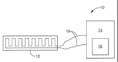
(0032] Referring to Figure 1, a simplified heater system in block
diagram format in accordance with one form of the present invention is
illustrated
and generally indicated by reference numeral 10. The heater system 10
comprises a layered heater 12, a two-wire controller 14, which is preferably
microprocessor based, and a power source,, 16 within or connected to the two-
wire controller 14. The layered heater 12 is connected to the two-wire
controller
14 as shown through a single set of electrical leads 18. Power is provided to
the
layered heater 12 through the electrical leads 18, and temperature information
of
the layered heater 12 is provided on command to the two-wire controller 14
through the same set of electrical leads 18. More specifically, the two-wire
controller 14 determines the temperature of the layered heater 12 based on a
calculated resistance, one technique of which is described in greater detail
below.
The two-wire controller 14 then sends signals to the power source 16 to
control
the temperature of the layered heater 12 accordingly. Therefore, only a single
set of electrical leads 18 is required rather than one set for the heater and
one set
for a temperature sensor.
(0033] Referring now tov Figure 2, in one form the layered heater 12
comprises a number of layers disposed on a substrate 20, wherein the substrate
20 may be a separate element disposed proximate the part or device to be
heated, or the part or device itself. As shown, the layers preferably comprise
a
dielectric layer 22, a resistive layer 24, and a protective layer 26. The
dielectric
_g_
CA 02546826 2006-05-19
WO 2005/053360 PCT/US2004/039500
layer 22 provides electrical isolation between the substrate 20 and the
resistive
layer 24 and is disposed on the substrate 20 in a thickness commensurate with
the power output of the layered heater 12. The resistive layer 24 is disposed
on
the dielectric layer 22 and provides two primary functions in accordance with
the
present invention. First, the resistive layer 24 is a resistive heater circuit
for the
layered heater 12, thereby providing the heat to the substrate 20. Second, the
resistive layer 24 is also a temperature sensor, wherein the resistance of the
resistive layer 24 is used to determine the temperature of the layered heater
12
as described in greater detail below. The protective layer 26 is preferably an
insulator, however other materials such as a conductive material may also be
employed according to the requirements of a specific heating application while
remaining within the scope of the present invention.
[0034] As further shown, terminal pads 28 are disposed on the
dielectric layer 22 and are in contact with the resistive layer 24.
Accordingly,
electrical leads 30 are in contact with the terminal pads 28 and connect the
resistive layer 24 to the two-wire controller 14 (not shown) for power input
and for
transmission of heater temperature information to the two-wire controller 14.
Further, the protective layer 26 is disposed over the resistive layer 24 and
is
preferably a dielectric material for electrical isolation and protection of
the
resistive layer 24 from the operating environment. Since the resistive layer
24
functions as both a heating element and a temperature sensor, only one set of
electrical leads -30, (e.g.,- two wires), are required for-the heater system
10, rather
than one set for the layered heater 12 and another set for a separate
temperature
sensor. Thus, the number of electrical leads for any given heater system is
reduced by 50% through the use of the heater system 10 according to the
_g_
CA 02546826 2006-05-19
WO 2005/053360 PCT/US2004/039500
present invention. Additionally, since the entire resistive layer 24 is a
temperature sensor in addition to a heater element, temperature is sensed
throughout the entire heater element rather than at a single point as with
many
conventional temperature sensors such as a thermocouple.
[0035] In another form of the present invention as shown in Figure
3a, the resistive layer 24 is disposed on the substrate 20 in the case where
the
substrate 20 . is not conductive and electrical isolation is not required
through a
separate dielectric layer.. As shown, the protective layer 26 is disposed over
the
resistive layer 24 as previously described. In yet another form as shown in
Figure 3b, the resistive layer 24 is disposed on the substrate 20 with no
dielectric
layer 22 and no protective layer 26. Accordingly, the heater system 10 of the
present invention is operable with at least one layer, namely, the resistive
layer
24, wherein the resistive layer 24 is both a heating element and,aa
temperature
sensor. Other combinations of functional layers not illustrated herein may
also be
employed according to specific application requirements while remaining within
the scope of the present invention.
[0036]~ Generally, the layered heater 12 is configured for operation
with any number of devices that require heating, one of which is hot runner
nozzles for injection molding systems as described in greater detail below.
Furthermore, the layered heater 12 is preferably a thick film heater that is
fabricated using a film printing head in one form of the present invention.
Fabrication of the layers-using this thick film process is shown-and described-
in
U.S. Patent No. 5,973,296, which is commonly assigned with the present
application and the contents of which are incorporated herein by reference in
-10-
CA 02546826 2006-05-19
WO 2005/053360 PCT/US2004/039500
their entirety. Additional thick film processes may include, by way of
example,
screen printing, spraying, rolling, and transfer printing, among others.
[0037] However, in another form, the layered heater 12 is a thin film
heater, wherein the layers are formed using thin film processes such, as ion
plating, sputtering, chemical vapor deposition (CVD), and physical vapor
deposition (PVD), among others. Thin film processes such as those disclosed in
U.S. Patent Nos. 6,305,923, 6,341,954, and 6,575,729, which are incorporated
herein by reference in their entirety, may be employed with the heater system
10
as described herein while remaining within the scope of the present invention.
In
yet another form, the layered heater 12 is a thermal sprayed heater, wherein
the
layers are formed using thermal spraying processes such as flame spraying,
plasma spraying, wire arc spraying, and HVOF (High Velocity Oxygen Fuel),
among others. In still another form, the layered heater 12 is a "sol-gel"
heater,
wherein the layers are formed using sol-gel materials. Generally, the sol-gel
layers are formed using processes such as dipping, spinning, or painting,
among
others. Thus, as used herein, the term "layered heater" should be construed to
include heaters that comprise at least one functional layer (e.g., resistive
layer 24
only, resistive layer 24 and protective layer 26, dielectric layer 22 and
resistive
layer 24 and protective layer 26, among others), wherein the layer is formed
through application or accumulation of a material to a substrate or another
layer
using processes associated with thick film, thin film, thermal spraying, or
sol-gel,
among-others. These processes are also referred to as -"layered- processes" or
"layered heater processes."
[0038] In order for the resistive layer 24 to serve both the function of
a temperature sensor in addition to a heater element, the resistive layer 24
is
-11-
CA 02546826 2006-05-19
WO 2005/053360 PCT/US2004/039500
preferably a material having a relatively high temperature coefficient of
resistance
(TCR). As the resistance of metals increases with temperature, the resistance
at
any temperature t (°C) is:
[0039] R = Ro(1 + at) (Equation 1)
[0040] where: Ro is the resistance at some reference temperature
(often 0°C) and a is the temperature coefficient of resistance (TCR).
Thus, to
determine the temperature of the heater, a resistance of the heater is
calculated
by the two-wire controller 14 as described in greater detail below. In one
form,
the voltage across and the current through the heater is measured using the
two-
wire controller 14, and a resistance is calculated based on Ohm's law. Using
Equation 1, or similar equations known to those skilled in the art of
temperature
measurement using Resistance Temperature Detectors (RTDs), and the known
TCR, temperature of the resistive layer 24 is then calculated and used for
heater
control.
[0041] Therefore, in one form of the present invention, a relatively
high TCR His preferred such that a small temperature change results in a large
resistance change. Therefore, formulations that include materials such as
platinum (TCR = 0.0039 S2JS2,/°C), nickel (TCR = 0.0041
S2JS~/°C), or copper (TCR
= 0.0039 S~/S~/°C), and alloys thereof, are preferred for the resistive
layer 24.
[0042] However, in other forms of the present invention, a material
for the resistive layer 24 need not necessarily have a high TCR. For example,
a
negative TCR material, or a material having a non-linear TCR, would also fall
within the scope of the present invention, as long as the TCR is predictable.
If
the TCR of a given material is known, if it can be measured with the necessary
-12-
CA 02546826 2006-05-19
WO 2005/053360 PCT/US2004/039500
accuracy, and if it is repeatable or predictable, then the material could be
used to
determine temperature of the heater system 10. Such a TCR, including the
relatively high TCR materials as described, are hereinafter referred to as
having
sufficient TCR characteristics. Accordingly, the materials described herein
and
their related high TCRs should not be construed as limiting the scope of the
present invention. The relatively high TCR as described herein are preferred
in
one form of the present invention.
[0043] As another sufFicient TCR characteristic, the material used
for the resistive layer 24 must not exhibit excessive "drift," which is a
tendency of
many resistive elements to change characteristics, such as bulk resistivity or
TCR, over time. Therefore, the material for the resistive layer 24 is
preferably
stable or predictable in terms of drift, however, the drift can be compensated
for
over time through calibration of the two-wire controller 14 that is described
in
greater detail below. Additionally, drift can be reduced or eliminated through
"burn-in" of the heater to induce any resistance shift that would occur over
time.
Accordingly, the resistive layer 24 is preferably a material that has a
relatively
high temperature coefficient of resistance and that is stable in terms of
drift.
However, if the drift is predictable, the material may be used for the
resistive layer
while remaining within the scope of the present invention.
[0044] In one form of the present invention, the resistive layer 24 is
formed by printing a resistive material on the dielectric layer 22 as
previously set
forth.- - More specifically, two (2) resistive materials were tested for use
in the
present invention, RI1 and R12, wherein the TCR of R11 was between
approximately 0.0008 S2,/S~/°C and approximately 0.0016
S2~/S~/°C, and the TCR of
-13-
CA 02546826 2006-05-19
WO 2005/053360 PCT/US2004/039500
R12 was between approximately 0.0026 52,/52,/°C and approximately
0.0040
S~/S~/°C. Additionally, temperature drift was tested for R11 and R12,
at various
temperatures, and the drift varied from approximately 3% for R11 to
approximately 10% for R12. With a "burn-in" as previously described, the'
drift
was shown to have been reduced to approximately 2% for R11 to approximately
4% for R12. The materials for the resistive layer 24 and their respective
values
for TCR and temperature drift as described herein are exemplary in nature and
should not be construed as limiting the scope of the present invention. Any
resistive material having sufficient TCR characteristics as previously set
forth can
be utilized for the resistive layer 24 while remaining within the scope of the
present invention.
[0045] Since a plurality of layered heaters having temperature
sensing capabilities are employed according to the present invention, the two-
wire controller 14 must be provided with certain information about the
heaters,
and more specifically the resistive layers 24, in order to properly calibrate
the
overall heater system. Parameters that are necessary for such calibration
include the cold resistance, the temperature at .which the cold resistance
value
was measured, and certain TCR characteristics (TCR at a temperature and/or
over a temperature range) in order to determine heater temperature from heater
resistance calculations. Preferably, the system automatically calculates the
cold
resistance of each layered heater 12 based on the measured voltage and current
using the two-wire controller 14 as described-in greater detail belov~i:
Additionally,-
the TCR characteristics for each layered heater 12 must be entered into the
system, e.g. the two-wire controller 14, using manual and/or electronic
methods.
-14-
CA 02546826 2006-05-19
WO 2005/053360 PCT/US2004/039500
Such values may be entered individually or as a single value for all layered
heaters 12 depending on, for example, whether or not the material for the
resistive layer 24 came from a common manufacturing lot. Regardless, the
calibration data, namely, the cold resistance, cold resistance temperature,
and
TCR of each layered heater 12 is preferably entered into the two-wire
controller
14 for more accurate and controlled operation of the heater system 10.
[0046] A variety of methods of providing the TCR characteristics
and cold resistance data of each layered heater 12 to the two-wire controller
14
may be employed while remaining within the scope of the present invention. For
example, each layered heater 12 may include a bar-coded tag that would be
scanned by an operator to download the cold resistance data and TCR
characteristics to the two-wire controller 14. Alternately, a smart card chip
or
other electronic means may be attached to each layered heater 12, which would
similarly be scanned by an operator to download the calibration data to the
two-
wire controller 14. In yet another form, the calibration data may be
downloaded
to the two-wire controller 14 via the Internet, for example, through a
supplier
website. Alternately, the TCR characteristics and cold resistance data may be
pre-programmed into the two-wire controller 14.
[0047] In addition to calibration for resistance data and TCR,
compensation for the resistance of electrical leads 30 is also provided by the
heater system 10 according to the present invention. Since the electrical
leads
add resistance to the circuit, temperature errors would. likely result if no
compensation for the increase in resistance were provided. Additionally, the
materials used for the electrical leads 30 may have a TCR higher than that of
the
25 resistive layer 24, which results in the portion of the electrical leads 30
that are
-15-
CA 02546826 2006-05-19
WO 2005/053360 PCT/US2004/039500
exposed to higher temperatures contributing more resistance. Therefore, the
two-wire controller 14 also provides for calibration of lead wire resistance.
[0048] The two-wire controller 14 is preferably designed with
temperature calibration capabilities, which further reduces long term
temperature
errors due to drift. One method of temperature calibration is accomplished by
using one or more pre-existing thermocouples, or other pre-existing
temperature
sensors, to ascertain both the temperature and the stability of the
temperature.
The temperature data from the thermocouples is then transmitted to the two-
wire
controller 14 for the resistance calculations. Further, changes in the
measured
cold resistance of the layered heater 12 may be used to calculate new TCR
values as appropriate. In another form for temperature calibration, the two-
wire
controller 14 preferably comprises a calibration offset feature that provides
for
input of a temperature offset parameter. Such an offset is desirable when the
location of the layered heater 12 is some distance away from the optimum
location for sensing temperature. Thus, the temperature offset parameter may
be
used such that the heater system 10 provides a temperature that more closely
represents the actual temperature at the optimum location.
[0049] Turning now to the construction of the layered heater 12 as
shown in Figures 4a-4c, the resistive layer 24 is preferably disposed on the
dielectric layer 22 in a pattern 40 that results in a desired temperature
profile for
the given substrate or element being heated. Figure 4a shows a resistive layer
24a in a rectangular pattern 40a based on the rectangular profile of the
substrate
20a. Figure 4b shows a resistive layer 24b in a circular pattern 40b based on
the
circular profile of the substrate 20b. Figure 4c shows a resistive layer 24c
in a
spiral pattern 40c based on a cylindrical shape of the substrate 20c.
Additionally,
-16-
CA 02546826 2006-05-19
WO 2005/053360 PCT/US2004/039500
the width "W" and/or pitch "P" of the patterns 40a-c may also be altered
according
to the specific heating requirements of the heater system. Therefore, the
pattern
of the resistive layer 24a is preferably customized for each application of
the
heater system 10. The patterns illustrated herein are exemplary only and are
not
intended to limit the scope of the present invention.
[0050] The layered heater 12, including each of the layers and the
terminal pads 28 may also be constructed in accordance with U.S. Patent Nos.
6,410,894, 6,222,166, 6,037,574, 5,973,296, and 5,714,738, which are commonly
assigned with the present invention and the contents of which are incorporated
herein in their entirety, while remaining within the scope of the present
invention.
Accordingly, additional specificity with regard to further materials,
manufacturing
techniques, and construction approaches are not included herein for purposes
of
clarity and reference is thus made to the patents incorporated by reference
herein
for such additional information.
[0051] Two-Wire Controller (14)
[0052] One form of the two-wire controller 14 is illustrated in block
diagram format in Figure 5. As shown, the two-wire controller 14 generally
comprises a power source 50, a voltage and current measurement component
52, a power regulator component 54, and a microprocessor 56 in communication
with the layered heater 12. The microprocessor 56 is also in communication
with
a communications component 58, where certain output from the heater system
10 (e.g., temperature readings) is delivered-and also where input (e.g.;
updated
TCR values, calibration data, temperature set points, resistance set points)
may
be provided to the heater system 10.
-17-
CA 02546826 2006-05-19
WO 2005/053360 PCT/US2004/039500
[0053] Referring now to Figure 6, the voltage measurement
component 52 of the two-wire controller 14 is illustrated in greater detail.
Generally, the two-wire controller 14 applies a DC bias, or low level DC
current,
to the layered heater 12 during an AC power cycle zero-cross interval so that
the
current value times a nominal heater resistance results in a voltage that is
higher
than the full wave voltage at the zero crossing for a time period on each side
of
the zero value. During the time interval, the voltage of the layered heater 12
is
amplified and compared to a reference voltage, and power to the layered heater
12 is then controlled as further described herein. Application of the DC bias
is
further shown and described in U.S. Patent No. 4,736,091, which is commonly
assigned with the present application and the contents of which are
incorporated
by reference in their entirety. In another form of the present invention, an
AC
current may be used for the bias instead of the DC bias to determine the
resistance of the layered heater 12.
[0054] As shown, the two-wire controller 14 comprises a transistor
60, a diode 62, and a first resistor 64, wherein the first resistor 64
together with
the layered heater 12 form a voltage divider. For the DC bias, the transistor
60 is
turned on for a short time period, e.g., 200~,s, during the zero cross
interval and
further prevents current flow through the power source 50 (not shown) during
negative half cycles when the heater is receiving power. Additionally, the
diode
62 prevents current flow through the power source 50 during positive half
cycles
when the layered heater 1-2 is receiving power- The output of the layered
heater
12 is then sent through a second resistor 66 and into an opamp circuit 68 that
comprises an amplifier 70 and resistors 72, 74, and 76. The output voltage of
the
amplifier 70 is thus used to calculate resistance and determine the
temperature of
-18-
CA 02546826 2006-05-19
WO 2005/053360 PCT/US2004/039500
the layered heater 12, wherein the output voltage of the amplifier 70 is read
by an
A/D converter within the microprocessor 56. Further, during the DC bias time
period, conversion of the output voltage of the amplifier 70 from an analog
signal
to a digital signal takes place, and a gating pulse from a triac 80 is
delivered to
the layered heater 12 if the calculated resistance, or layered heater 12
temperature, is such that a control algorithm has determined a need for
additional
power from the layered heater 12. As further shown, a field effect transistor
82
clamps the input of the amplifier 70, thereby preventing .the amplifier 70
from
being over driven during both positive and negative half cycles when the
heater is
receiving line power. ,
[0055] The microprocessor 56, which is described in greater detail
below, generally communicates with the circuit shown through an output control
84, a bias control 86, and heater input 88. Additionally, the microprocessor
56
further comprises firmware 90, and/or software (not shown). The firmware 90
may be programmed for a variety of functions, including but not limited to,
allowing half cycle delivery of power to improve controllability or full cycle
power
in accordance with IEEE 519. As a further example, the firmware 90 may include
'' control algorithms to compensate for thermal transient response and other
calibration data as previously described. Therefore, the microprocessor 56 is
used in combination with the DC bias circuitry to determine layered heater 12
temperature and to more efficiently control power to the layered heater 12.
- - [0056] A further expansion- of the two-wire controller- 14 is now
shown in greater detail in Figure 7. The power source 50 is preferably non-
isolated and capacitively coupled with a linear regulator 100 as shown. The
power source 50 thus regulates an alternating current down to a specified
value
-19-
CA 02546826 2006-05-19
WO 2005/053360 PCT/US2004/039500
as required for operation. As further shown, the sine wave for the zero-cross
(DC
biasing) from the power source 50 is in communication with the microprocessor
56. During the zero-cross interval, the DC bias is applied through the
transistor
102, diode 104, and resistor 106. The voltage across the layered heater 12 is
amplified and offset by the amplifier 108, and the amplifier 110 is used as a
reference for the A/D converter within the microprocessor 56 for temperature
variances.
[0057] Measurement of the change in voltage across and current
through the layered heater 12 is accomplished using the dual amplifiers 112
and
114 and analog switches 116 and 118, wherein the change in voltage signal is
through amplifier 112 and analog switch 116, and the change in current is
through amplifier 114 and analog switch 118. As further shown, the change in
current is measured using a shunt resistor 116. Additionally, the two-wire
controller 14 comprises a triac 120 that is out of conduction at the zero-
cross and
is conducting on each half cycle. During the DC biasing interval, an A/D
conversion takes place and the triac 120 delivers a pulse if the measured
resistance is such that the control algorithm has determined a need for
additional
power from the layered heater 12. Therefore, two methods of calculating
resistance are provided by the circuit shown in Figure 7, namely, the DC bias
circuit and the shunt resistor circuit. Additionally, although the' present
invention
preferably measures voltage and current to determine resistance, alternate
methods of determining resistance such as a voltage gate orusing a known
current may also be employed while remaining within the scope of the present
invention.
-20-
CA 02546826 2006-05-19
WO 2005/053360 PCT/US2004/039500
[0058] In yet another form, the triac 120 is preferably a random fire
triac such that the layered heater 12 is fired at high conduction angles to
reduce
the amount of energy that is delivered to the layered heater 12 during
sampling.
For example, firing the layered heater 12 at conduction angles of 160°
and 340°
allows for sufficient sampling at 120Hz with reduced energy input to the
layered
heater 12. Alternately, sampling at only 160° or only 340° would
result in a
sampling rate of 60Hz while reducing the energy input further in half.
Additionally, when using a random fire triac, any rate function may be applied
by
delivering energy in smaller increments as the temperature (or resistance in
another form) approaches the set point. Accordingly, the layered heater 12 is
fired at higher and higher conduction angles into a full line cycle.
[0059] As further shown, communications to and from the two-wire
controller 14 take place on the opposite side of the microprocessor 56. The
communications component 58 comprises a series of opto-isolators 122, 124,
and 126, in addition to a line transceiver 128. Therefore, communications can
be
made through any number of protocols, including by way of example, RS-485
communications as illustrated herein. In addition to other functions,
calibration
data can be entered utilizing this communications interface.
[0060] The firmware 90 is loaded into the microprocessor 56 using
the ISP (In-System Programming) connections as shown. Therefore, certain
modifications to the settings within the two-wire controller 14, including
entry of
calibration data as previously described, can--be -accomplished in an
efficient -
manner.
[0061] The specific circuit components, along with the values and
configuration of the circuit components, (e.g., resistor values, capacitor
values,
-21-
CA 02546826 2006-05-19
WO 2005/053360 PCT/US2004/039500
among others), as detailed in Figure 7 are exemplary of one form of the two-
wire
controller 14 and should not be construed as limiting the scope of the present
invention. Accordingly, alternate circuit components, configurations, and
values,
and resistance measuring circuit topologies may be implemented in a two-wire
configuration as defined herein while remaining within the scope of the
present
invention.
[0062] Hot Runner Nozzle Ap~~lication
[0063] One known application for the heater system 10 according to
the principles of the present invention is for hot runner nozzles in injection
molding systems as shown in Figure 8. The hot runner nozzles 150 are typically
disposed within a hot runner mold system 152, which further comprises a
plurality
of mold wiring channels 154 that provide for routing of electrical -leads (not
shown) that run from heaters (not shown) disposed proximate the hot runner
nozzles 150 to a two-wire controller (not shown) as described herein. Since
each
heater serves as both a heating element and as a temperature sensor, only one
set of leads per heater is required rather than one set of leads for the
heater and
one set of leads for a temperature sensor. As a result, the amount of leads
running through the mold wiring channels 154 is reduced in half and the
related
bulk and complexity is drastically reduced.
[0064] Additionally, injection molding equipment typically includes
an umbilical 164 that runs from the controller to the hot runner mold system
152,
wherein all of the leads -and- other related electrical components are
disposed.
With the drastic reduction in the number of leads provided by the present
invention, the size and bulk of the umbilical 164 is also drastically reduced.
Moreover, since the temperature is being sensed by the entire resistive layer
of
-22-
CA 02546826 2006-05-19
WO 2005/053360 PCT/US2004/039500
the heater, the temperature is being sensed over a length rather than at a
point
with a conventional thermocouple.
[0065] Referring now to Figures 9 and 10, the heater system for a
hot runner nozzle 150' is illustrated in greater detail. The heater system 200
9
comprises a layered heater 202 disposed around a body 203 of the hot runner
nozzle 150', and a two-wire controller 204 in communication with the layered
heater 202 through a single set of leads 205. The layered heater 202 further
comprises a substrate 206, which is configured to fit around the geometry of
the
hot runner nozzle 150' (shown as cylindrical). The layered heater 202 further
comprises a dielectric layer 208 disposed on the substrate 206, a resistive
layer
210 disposed on the dielectric layer 208, and a protective layer 214 disposed
on
the resistive layer 210. As further shown, terminal pads 216 are disposed on
the
dielectric layer 208 and are in contact with the resistive layer 210.
Accordingly,
the electrical leads 205 are in contact with the terminal pads 216 and connect
the
resistive layer 210 to the two-wire controller 204. As a result, only one set
of
electrical leads 205 are required for the heater system 200, rather than one
set
for the layered heater 202 and another set for a separate temperature sensor.
[0066] As shown in Figure 11, in an alternate form a layered heater
202' is disposed on an outer surface 220 of the hot runner nozzle 150' rather
than
on a separate substrate as previously described. Similarly, the layered heater
202' comprises a dielectric layer 208' disposed on the outer surface 220, a
resistive- layer 210' disposed on -the -dielectric layer 208', and a
protective layer
214' disposed on the resistive layer 210'. Terminal pads 216' are similarly
disposed on the dielectric layer 208' and are in contact with the resistive
layer
-23-
CA 02546826 2006-05-19
WO 2005/053360 PCT/US2004/039500
210'. As further shown, the single set of leads 205' connect the heater 202'
to
the two-wire controller 204'.
[0067] In yet another form of the present invention, a modular
solution to retrofitting the heater system according to the present invention
with
existing controllers that use separate temperature sensors, e.g.,
thermocouples,
RTDs, thermistors, is provided and illustrated in Figure 12. As shown, two-
wire
modules 230 are provided between layered heaters 232 and an existing
temperature controller 234. The temperature controller 234 comprises
temperature sensor inputs 236 and power outputs 238. The two-wire modules
230 thus contain the two-wire resistance measuring circuit as previously
described, and the temperatures calculated within the two-wire modules 230 are
transmitted to the temperature sensor inputs 236 of the existing temperature
controller 234. Based on these temperature inputs, the temperature controller
234 controls the layered heaters 232 through the power outputs 238. It should
be
understood that power control may be a part of the temperature controller 234
or
may be a separate power controller 240 as shown while remaining within the
scope of the present invention. Accordingly, existing temperature controllers
can
be retrofitted with the two-wire modules 230 to implement the heater system of
the present invention without substantial rework and modification of existing
systems.
[0068] Referring now to Figure 13, another form of a heater system
according- the present invention that reduces the number of electrical leads
is
illustrated and generally indicated by reference numeral 300. The heater
system
300 comprises a layered heater 302 and a controller 304 that operate as
previously described wherein a resistive layer (not shown) of the layered
heater
-24-
CA 02546826 2006-05-19
WO 2005/053360 PCT/US2004/039500
302 is both a heating element and a temperature sensor. The heater system 300
further comprises a power source 306, which is preferably low voltage in one
form of the present invention, that provides power to the layered heater 302.
The
layered heater 302 is connected to the controller 304 as shown through a
single
electrical lead 308 and through the body or structure of a device 310 (e.g.,
hot
runner nozzle system mold) designated as a common return or neutral, wherein
the common return device 310 provides an electrical return to the controller
304
from the layered heater 302. The heater system 300 uses the electrically
conductive nature of the device 310 materials to complete the electrical
circuit,
and thus a power source 306 is required to limit the current level traveling
through the device 310. Therefore, since the device structure 310 is being
used
to connect the layered heater 302 to the controller 304, another electrical
lead is
eliminated such that the controller 304 is effectively a "single-wire
controller."
[0069] The description of the invention is merely exemplary in
nature and, thus, variations that do not depart from the gist of the invention
are
intended to be within the scope of the invention. Such variations are not to
be
regarded as a departure from the spirit and scope of the invention.
-25-