Note: Descriptions are shown in the official language in which they were submitted.
CA 02547167 2006-05-17
1 SYSTEM, METHOD AND APPARATUS FOR
2 CONDUCTING EARTH BOREHOLE OPERATIONS
3
4 FIELD OF THE INVENTION
The present invention relates to a system, method and apparatus for
6 performing earth borehole operations.
7
8 BACKGROUND OF THE INVENTION
9 The use of coiled tubing (CT) technology in oil and gas drilling and
servicing has become more and more common in the last few years. In CT
11 technology, a continuous pipe wound on a spool is straightened and injected
into
12 a well using a CT injector. CT technology can be used for both drilling and
13 servicing, e.g., workovers.
14 The advantages offered by the use of CT technology, including economy
of time and cost are well known. As compared with jointed-pipe technology
16 wherein typically 30-45 foot straight sections of pipe are threadedly
connected
17 one section at a time while drilling the wellbore, CT technology allows the
18 continuous deployment of pipe while drilling the well, significantly
reducing the
19 frequency with which such drilling must be suspended to allow additional
sections of pipe to be connected. This results in less connection time, and as
a
21 result, an efficiency of both cost and time.
22 However, the adoption of CT technology in drilling has been less
23 widespread than originally anticipated as a result of certain problems
inherent in
24 using CT in a drilling application. For example, because CT tends to be
less
robust than jointed-pipe for surface-level drilling, it is often necessary to
drill a
-1-
CA 02547167 2006-05-17
1 surface hole using jointed-pipe, cement casing into the surface hole, and
then
2 switch over to CT drilling. Additionally, when difficult formations such as
gravel
3 are encountered down-hole, it may be necessary to switch from CT drilling to
4 jointed-pipe drilling until drilling through the formation is complete, and
then
switch back to CT drilling to continue drilling the well. Similarly, when it
is
6 necessary to perform drill stem testing to assess conditions downhole, it
may
7 again be necessary to switch from CT drilling to jointed-pipe drilling and
then
8 back again. Finally, a switch back to jointed pipe operations is necessary
to run
9 casing into the drilled well. In short, in CT drilling operations it is
generally
necessary for customers and crew to switch back and forth between a CT
drilling
11 rig and a jointed-pipe conventional drilling rig, a process which results
in
12 significant down-time as one rig is moved out of the way, and the other rig
put in
13 place.
14 Another disadvantage of CT drilling is the time consuming process of
assembling a (bottom-hole-assembly (BHA) - the components at the end of the
16 CT for drilling, testing, well servicing, etc.), and connecting the BHA to
the end of
17 the CT. Presently, this step is performed manually through the use of
rotary
18 tables and make-up/breakout equipment. In some instances, top drives are
used
19 but the CT injector and the top drive must be moved out of each others way,
i.e.,
they cannot both be in line with the borehole. Not only does this process
result
21 in costly downtime, but it can also present safety hazards to the workers
as they
22 are required to manipulate heavy components manually.
23 To address the problems above associated with the use of CT technology
24 and provide for selective and rapid switching from the use of a CT injector
to a
top drive operation, certain so-called "universal" or "hybrid" rigs have been
-2-
CA 02547167 2006-05-17
1 developed. Typical examples of the universal rigs, i.e., a rig which
utilizes a
2 single mast to perform both top drive and CT operations, the top drive and
the
3 CT injector being generally at all times operatively connected to the mast,
are
4 shown in United States Patent Publication 2004/0206551; and United States
Patent Nos. 6,003,598, and 6,609,565. Thus, in U.S. Publication 2004/0206551
6 there is disclosed a rig adapted to perform earth borehole operations using
both
7 CT and/or jointed-pipes, the CT injector and a top drive being mounted on
the
8 same mast, the CT injector being selectively moveable between a first
position
9 wherein the CT injector is in line with the mast of the rig and hence the
earth
borehole and a second position wherein the CT injector is out of line with the
11 mast and hence the earth borehole.
12 In all of the systems disclosed in the aforementioned patents, publications
13 and the cross-referenced related applications, the reel of CT and the CT
injector
14 are on or are carried by the same carrier. Heretofore in CT operations
particularly drilling, well depth has been limited to about 2200 meters
because of
16 governmental regulations regarding the weight and/or height of loads moving
on
17 highways. A CT injector can weigh from 20,000 to 40,000 Ibs depending upon
18 its size. As to the CT itself, 2200 meters of 3 '/2' CT, including the reel
upon
19 which it is wound can weigh from 60,000 to 80,000 Ibs. Thus, because of
governmental regulations regarding weight that can be transported on highways,
21 reels of 3 '/Z" CT exceeding about 2200 meters cannot be transported on
most
22 highways since the combined weight of the CT and the CT injector would
exceed
23 the weight limitations. Clearly it is possible to transport greater lengths
of
24 smaller diameter, e.g., 2 %8" CT. However, particularly in using CT to
conduct
drilling operations at depths of about 2200 meters, the hydraulics of fluid
flow,
-3-
CA 02547167 2006-05-17
1 e.g., flow of drilling mud, dictate that the CT be 3 %Z" or greater in
diameter.
2 In prior art CT systems wherein a reel or spool of CT is mounted on a
3 carrier, the spool is positioned on the carrier such that the core on which
the CT
4 can be wound does not extend for the maximum width of the carrier. This is
because the drive assembly used to rotate the spool is on the side of the
spool
6 meaning that the drive assembly takes up some of the lateral spacing between
7 the opposed sides of the CT carrier. Since this reduces the overall length
of the
8 spool and hence the length of the winding core, less CT can be wound upon
the
9 spool in these prior art systems.
-4-
CA 02547167 2006-05-17
1 SUMMARY OF THE INVENTION
2 In one aspect the present invention provides a system for use in
3 conducting earth borehole operations, the system comprising a CT carrier and
a
4 reel of CT rotatably mounted thereon. The system further comprises a
separate,
mast carrier having a mast which is movable from a lowered, e.g., horizontal
6 position, for transportation to a position transverse to the horizontal,
e.g.,
7 generally vertical. A top drive is carried by the mast for longitudinal
movement
8 therealong. Carried on the mast carrier and either connected to or
connectable
9 to the mast, is a CT injector.
In another aspect the present invention provides a CT carrier having first
11 and second sides and a reel assembly comprising a spool of CT rotatably
12 mounted thereon and a drive system for rotating the spoof of CT. The spoof
has
13 first and second, spaced rims which are near the first and second sides,
14 respectively. The spacing between the rims provide a CT winding core which
makes maximum utilization of the width of the carrier vis-a-vis being able to
wind
16 more CT on the spool. There is also a drive assembly for rotating the
spool.
-5-
CA 02547167 2006-05-17
1 BRIEF DESCRIPTION OF THE DRAWINGS
2 Fig. 1 is a side, elevational view showing the CT carrier attached to a
3 tractor for transport.
4 Fig. 2 is a side, elevational view showing the mast carrier with the mast in
a position for transport.
6 Fig. 3 is a side, elevational view showing the CT carrier married to the
7 mast carrier and in a position for transport over non-governmental regulated
8 highways or the like.
9 Fig. 4 is a side, elevational view showing the CT rig married to the mast
rig and the mast in an erected position to perform jointed pipe operations
with
11 the top drive carried by the mast.
12 Fig. 5 is a side, elevational view of the CT carrier and the mast carrier
13 married to one another and showing a CT injector movably connected to a
slide
14 supported on the mast.
Fig. 6 is a side, elevational view showing a CT carrier married to the mast
16 carrier with the mast moved laterally off vertical whereby the CT injector
17 connected thereto can be positioned over a wellbore/wellhead with the CT
18 issuing therefrom in line with the wellbore; and
19 Fig. 7 is a side, elevational view of another embodiment of the present
invention showing a CT carrier married to a mast carrier wherein the mast
carrier
21 is of the skid design.
22 Fig. 8 is a top plan view of one embodiment of one embodiment of a CT
23 carrier of the present invention.
24 Fig. 9 is a side, elevational view of a portion of the CT carrier shown in
Fig. 8.
-6-
CA 02547167 2006-05-17
1 Fig. 10 is a side, elevational view of a mechanism for adjusting the
2 position of the drive assembly used in the CT carrier shown in Figs. 8 and
9.
3 Fig. 11 is a top plan view of another embodiment of the CT carrier of the
4 present invention.
Fig. 12 is a side elevational view of the CT carrier shown in Fig. 11.
6 Fig. 13 is a side, elevational view of a mechanism for adjusting the
7 position of the drive assembly of the embodiment shown in Figs. 11 and 12.
8 Fig. 14 is a fragmentary, perspective view of another embodiment of the
9 CT carrier of the present invention; and
Fig. 15 is a fragmentary, top plan view of a CT carrier showing a way to
11 increase winding core length.
12
_7_
CA 02547167 2006-05-17
1 DETAILED DESCRIPTION OF PREFERRED EMBODIMENTS
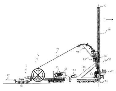
2 Turning first to Fig. 1, there is shown a CT carrier, shown generally as 10,
3 having rotatably journaled thereon a reel 12 of CT. As seen, CT carrier 10
is of
4 the wheeled design and comprises a platform 14 on a suitable frame (not
shown)
and having a tongue 16 which via a fifth wheel 18 is selectively, releasably
and
6 rotatably connected to a trailer 20 of the wheeled variety, trailer 20 being
7 connected via a second fifth wheel 22 on the bed 24 of a tractor 26. Thus,
the
8 CT carrier 10 carrying reel 12 of CT can be moved down the highway or from
9 site to site in a drilling or well servicing area.
Fig. 2 depicts a mast carrier, shown generally as 30 comprising a
11 substructure 32. As shown, carrier 30 is also of the wheeled variety.
Pivotally
12 secured to carrier 30 as at 34 is a mast 36 in which is mounted a top drive
13 shown as 38. As is well known to those skilled in the art, top drive 38 is
14 connected to a crown block 40, suitable cables extending from crown block
40 to
top drive 38. Mast carrier 30 also includes a working platform 42 which can
16 include a rotary table.
17 As seen in Figs. 3 and 4, mast 36 is movable from a lowered or transport
18 position shown in Fig. 2 to a position transverse to the horizontal and
with
19 particular reference to Fig. 4 to a generally vertical position. Mast
carrier 30 also
includes a tongue 44 which has a fifth wheel connector 46 whereby mast carrier
21 30 can be connected to a tractor or the like for transport or as shown in
Fig. 5 to
22 CT carrier 10. It will be understood that mast carrier 30 and CT carrier
could be
23 of the self-propelled variety. Mast carrier 30 is also provided with a
support 48
24 upon which mast 36 rests when in transport, i.e., in the mode shown in Fig.
2.
Also resting on the substructure 32 of mast carrier 30 is an engine 50 and a
_g_
CA 02547167 2006-05-17
1 hydraulic tank 52 for the storage of hydraulic fluid used in operating the
various
2 hydraulic components of the system, e.g., motors, pistons/cylinder
3 arrangements, etc. As is well known, most of the components of the system of
4 the present invention may be operated hydraulically, electrically, or in
some
cases pneumatically. Also mounted on substructure 32 is a draw works 54
6 which as seen in Fig. 4 has cables 56 which run through a sheave assembly
(not
7 shown) to crown block 40.,
8 Attached to mast 36 is a CT injector 60 from the bottom of which extends
9 an articulated lubricator 62. Secured between mast 36 and substructure 32 of
carrier 30 is a piston/cylinder combination 64 which is used to raise mast 36.
A
11 piston/cylinder combination 66 is also connected between CT injector 60 and
a
12 portion 68a of guide or gooseneck 68 as best seen in Fig. 3.
13 Turning now to Fig. 3, mast rig 30 is shown with mast 36 having been
14 raised from the position shown in Fig. 2 to a slightly elevated position
using
cylinder 64 of which there are two, only one being shown. Also, as can be
seen,
16 piston/cyiinder combination 66 has been partially extended as a
commencement
17 of forcing portion 68a of guide 68 into a complete arc as shown in Fig. 4.
As can
18 also be seen, CT 70 has been unreeled from reel 12 and stabbed into CT
19 injector 60. It will also be observed that rig carrier 30 and CT carrier 10
are
married in the embodiment shown in Fig. 3 being connected by fifth wheel
21 connector or other suitable connection to CT carrier 10 allowing pivotal
22 movement between rig carrier 30 and CT carrier 10. Thus it will be seen
that at
23 least in one embodiment, CT carrier 10 and rig carrier 30 can be
selectively,
24 releasably connected to one another and the combined carriers pulled as a
single unit which would most likely occur if the system was being moved from
_g_
CA 02547167 2006-05-17
1 one drilling or servicing site to another drilling or servicing site and did
not have
2 to traverse governmental regulated highways. As can also be seen, when this
is
3 occurring, a booster trailer 80 would be connected by a fifth wheel
connection or
4 some other suitable connection to the rear of rig carrier 30.
Turning now to Fig. 4, the system is shown with mast 36 erected to a
6 general vertical position. As can be seen, CT injector 60 is attached to
mast 36
7 such that an axis running through CT injector 60 and an axis passing through
top
8 drive 38 are at an angle to one another. In the position shown in Fig. 4, CT
9 injector 60 would be inoperative since CT issuing therefrom would not be in
line
with wellhead 84 of the wellbore below but not shown. Rather, in the
11 configuration of Fig. 4, top drive 38 could perform jointed pipe operations
since
12 the axis of top drive 38 is in line with wellhead 84. It will be
appreciated that if
13 mast 36 is now moved in the direction of arrow C, mast 36 being pivotally
14 secured to substructure 32, CT injector can be brought to a position where
the
axis therethrough is substantially coincident with the axis of wellhead 84.
16 Accordingly, CT issuing from CT injector 60 will be in line with wellhead
84 and
17 can be injected into the wellbore therebelow.
18 Turning now to Fig. 5, there is shown a variation of the system of the
19 present invention wherein CT injector 60 is slidably fixed to a slide 82
which in
turn is affixed to the mast 36 at the juncture of the mast and the
substructure 32.
21 It will be understood that slide 82 and mast 36 will always be at an angle
to one
22 another and, accordingly, to position CT injector over wellhead 84 mast 36
has
23 to be tilted as shown. When it is desired to perform top drive operations
with top
24 drive 38, mast 36 would then be moved to a substantially vertical position
meaning that slide 82 would then be at an angle to the horizontal much like
mast
-10-
CA 02547167 2006-05-17
1 36 is as shown in Fig. 5.
2 As best seen in Fig. 5, slide 82 permits CT injector 60 to be moved axially
3 toward and away from wellhead 84. CT injector 60 can be connected to slide
82
4 by a collar 83 or the like which can be pinned or otherwise positioned at
desired
locations along the length of slide 82. In the position shown in Fig. 5, CT
injector
6 60 is in the operative position, i.e., lubricator 62 can be connected if
necessary to
7 wellhead 84 in the well known manner and CT 70 injected through wellhead 84
8 into the wellbore there below. It will also be observed that in the position
shown
9 in Fig. 5, top drive 38 is moved upwardly in mast 36 towards crown 40 so as
to
not interfere with the movement of CT injector 60 along slide 82. Thus, as
11 shown in Fig. 5, CT injector is shown in two positions, the lowermost being
when
12 CT is being injected through wellhead 84 into the wellbore therebelow.
13 Fig. 6 depicts the embodiment shown in Fig. 4 wherein CT injector 60 is
14 hung off of the side of the mast 36 such that top drive 38 is at an angle
to
wellhead 84 whereas CT injector 60 is substantially in line with the wellhead
84
16 meaning that CT 70 issuing therefrom is generally in line with wellhead 84
above
17 the wellbore. In the embodiment shown in Fig. 6, the axes of top drive 38
in CT
18 injector 60 are always at an angle to one another. However, in the
configuration
19 shown in Fig. 6, CT injector 60 is in line with wellbore 84 meaning that
top drive
38 is in an inoperative position since the axis of top drive 38 is at an angle
to
21 wellhead 84. It will be appreciated that by tilting mast 36 in the
direction of arrow
22 A, the axis of top drive 38 can be made coincident with wellhead 84 in
which
23 event top drive 38 can conduct jointed pipe operations and CT injector 60
will be
24 in an inoperative position since it will now be off-axis with respect to
wellhead 84.
Mechanisms for supporting CT injector 60 off of mast 36 in the
-11-
CA 02547167 2006-05-17
1 embodiments shown in Figs. 4 and 6 are disclosed in one or more of the above
2 identified cross referenced applications. Suffice to say that numerous
3 techniques can be employed to suspend CT injector 60 off of mast 36 in the
4 configuration shown in Figs. 4 and 6. In this regard, CT injector 60 can be
affixed to mast 36 at all times or can be selectively latched onto mast 36 as
6 desired. In the latter case, CT injector 60 would rest on substructure 32 of
mast
7 carrier 30a and, when mast 36 was moved to a position such as shown in Fig.
2,
8 could then be latched onto mast 36.
9 Referring now to Fig. 7 there is shown another embodiment of the present
invention. In the embodiment shown in Fig. 7, CT carrier 10 is substantially
as
11 shown above with respect to the other embodiments; however, rig carrier 30b
12 differs in that rather than being a wheeled carrier, it is in a skid form
such that
13 substructure 32a can be pulled along the ground if necessary once
outriggers 33
14 have been raised. Alternatively, substructure 32a, once outriggers 33 have
been
raised, can be pulled onto a wheeled trailer or the like for transport. In the
16 embodiment shown in Fig. 7, substructure 32a supports a sliding platform
100
17 which can be moved horizontally using a piston/cylinder combination 102.
18 Thus, CT injector 60 can be attached to mast 36 such that at all times both
the
19 axes of CT injector 60 and top drive 38 at all times remain vertical and
essentially parallel to one another. Accordingly, by horizontal movement of
the
21 platform 100 via the action of piston/cylinder combination 102, either CT
injector
22 60 or top drive 38 can be selectively positioned over the wellhead, i.e.,
such that
23 either the axis of top drive 38 is coincident with the wellhead or the axis
of CT 60
24 is coincident with the wellhead.
Referring now to Figs. 8, 9 and 10 there is shown as embodiment of a CT
-12-
CA 02547167 2006-05-17
1 carrier which permits a maximum length winding core for CT around the drum
of
2 the reel assembly. Referring first then to Fig. 8, the carrier, shown
generally as
3 200, can be of the wheeled variety as discussed above with respect to the
carrier
4 shown in Figs. 1-7. In this regard it should be noted that both the CT
carrier and
the rig carrier can be wheeled, self-propelled, in the form of a skid or any
other
6 form of support which can hold the various components, e.g., the reel of CT,
the
7 mast, etc. Returning then to Fig. 8, carrier 200 has a frame shown generally
as
8 202 comprising first and second, side frame members 204 and 206 connected
9 by cross braces 208. First and second angled members 210 and 212 can form a
tongue (not shown) whereby carrier 200 can be pulled by a tractor or the like.
11 Mounted on carrier 200 is a reel assembly shown generally as 214. Reel
12 assembly 214 comprises first and second pillow blocks 216 and 218 which are
13 attached to side frame members 204 and 206, respectively. Pillow blocks 216
14 and 218 are substantially the same. Accordingly for simplicity, only the
structure
of pillow block 218 will be described. As seen in Fig. 9, pillow block shown
16 generally as 218 is comprised of two, hinged sections, a lower section 220
and
17 an upper section 222, the sections being hingedly secured to one another by
18 pivot pin 224. It will be appreciated that when section 222 is opened, the
reel
19 assembly 214 can be removed from carrier 208. In any event, in the closed
position shown in Fig. 9, section 222 engages section 220, section 222 being
21 held firmly against section 220 by means of a threaded pin 226 received
through
22 a tongue portion 228 of section 222 and threadedly received in a block 230
23 affixed to frame member 206. Reel assembly 214 further includes a
cylindrical
24 drum 240 which is connected by a series of spokes 242 to an axle 246, drum
240 and axle 246 being generally concentric with respect to one another. As
can
-13-
CA 02547167 2006-05-17
1 be seen, the inner surface 241 a of drum 240, forms an annulus 241 b between
2 axle 246 and surface 241 a. Axle 246, as will be appreciated by those
skilled in
3 the art, is rotatably journaled in pillow boxes 216 and 218. First and
second
4 spaced rims 248 and 250 are secured to or near the opposite ends of drum 240
and form a winding core determined by the spacing between the rims 248 and
6 250. As best seen in Fig. 8, because the rims 248 and 250 are near the side
7 frame members 204 and 206, the winding core effectively extends for almost
the
8 full width of carrier 200. This is to be contrasted with prior art CT
carriers
9 wherein the winding core was substantially less because the rims on the reel
were not positioned near the respective sides of the carrier. Rather, although
11 one of the rims could be positioned adjacent one side of the carrier, the
other rim
12 was substantially inboard, e.g., up to 3 feet, to accommodate the drive
13 mechanism to rotate the spool.
14 Mounted on side frame member 206 is a drive assembly shown generally
as 260. Drive assembly 260 comprises a motor 262 and a gear box 264. A spur
16 gear 266 is driven by internal gearing in gearbox 264 which in turn is
driven by
17 motor 262. Drive assembly 260 is mounted on an arm 280 which is pivotally
18 secured to frame member 206 by a pivot pin 270. Thus, as can be seen, drive
19 assembly 260 can be pivoted from a first position wherein it is fully
confined
within the frame 202 of carrier 200 to a second position where it extends
outside
21 of frame 202 generally aligned with side frame member 206.
22 Arm 280 is provided with elongated slots 284 and 286. Supported on arm
23 280 is a slide plate 288 upon which drive assembly 260 rests, drive
assembly
24 260 as shown in Fig. 10 having a flange 290.
When drive assembly 260 is pivoted to the second position described
-14-
CA 02547167 2006-05-17
1 above, the spur gear 266 will be moved into the annulus 241 between axle 246
2 and the inside surface 241 a of drum 240. As best seen with reference to
Fig. 9,
3 its inner surface of rim 250 or for that matter the inner surface 241 a of
drum 240
4 has a series of circumferentially disposed teeth 292. Teeth 292 are of a
size and
shape that mesh with the teeth of gear 266. By adjusting drive assembly 260
6 such that gear 266 engages teeth 292, it will be seen that as gear 266 is
rotated
7 via gearbox 264, drum 240 will also be caused to rotate.
8 To ensure proper engagement between gear 266 and teeth 292, the drive
9 assembly 260 is adjustable in a direction generally lengthwise of side frame
member 206. Again referring to Fig. 10, it can be seen that once arm 280 has
11 been pivoted to the position where gear 266 is received in annulus 241 b,
slide
12 plate 288 can be moved longitudinally relative to side frame member 206 by
13 adjustment screws 300 having locking nuts 302, the screws engaging a flange
14 301 formed on slide plate 288. Once gear 266 is properly engaged with teeth
292, nut and bolt assemblies 304 and 306 can be tightened to ensure that the
16 drive assembly 260 does not move and gear 266 remains in driving contact
with
17 teeth 292.
18 Turning now to Fig. 11, there is shown another way in which maximum
19 winding core length can be achieved by a CT carrier. CT carrier, shown
generally as 400 like CT carrier 200 has a frame shown generally as 402
21 generally constructed in the same manner as frame 202. Additionally, the
reel
22 assembly, shown generally as 403, in terms of how it is mounted on the
frame is
23 essentially the same as the embodiment shown in Figs. 8-10. Accordingly,
for
24 the sake of simplicity, the description of the reel assembly 403 will be
dispensed
with except as is necessary to explain the operation of the embodiment shown
in
-15-
CA 02547167 2006-05-17
1 Figs. 11-13. A drive assembly shown generally as 404 comprising a motor 406
2 and a gearbox 408 is mounted to the underside of a side frame member 410 of
3 frame 402. As seen in Fig. 12, gearbox 408 drives a spur gear 411 by
internal
4 gearing, well known to those skilled in the art, in gearbox 408. Rim 412 of
the
spool of reel assembly 403 is provided on its outer periphery with a series of
6 teeth 414 which mesh with the teeth on spur gear 411. Thus it can be seen
that
7 when spur gear 411 engages teeth 414 on the periphery of rim 412, rim 412
and
8 hence the drum 405 of the reel assembly 403 can be rotated in either
direction
9 depending upon the direction of rotation of spur gear 411.
To ensure proper meshing between spur gear 411 and teeth 414, drive
11 assembly 404, like drive assembly 260 shown in Figs. 8-10 is adjustable. As
12 shown in Fig. 12, a piston/cylinder assembly 416 connected between side
frame
13 member 410 and drive assembly 404 and can be used to move drive assembly
14 404 in a direction generally parallel to side frame member 410. Once gear
411
is properly engaged with teeth 414, drive assembly can be held in place by
16 piston/cylinder combination 416. Alternatively, essentially the same
adjustment
17 mechanism used with respect to the embodiment shown in Figs. 8-10 can be
18 used as shown in Fig. 13. Referring then again to Fig. 13, there is a plate
420
19 secured to the underside of frame member 410 upon which is carried a slide
plate 422. Plate 420 has spaced slots 424 and 426. Extending through holes in
21 the slide plate 422 are nut and bolt assemblies 428 and 430 which also
extend
22 through slots 426 and 424, respectively. Thus, once the spur gear 411 is
23 properly engaged with teeth 414, nut and bolt assemblies 428 and 430 can be
24 tightened to maintain the position of drive assembly 404 relative to the
rim 412.
As also is shown in Fig. 13, rather than using a piston/cylinder combination
such
-16-
CA 02547167 2006-05-17
1 as 416 to position the drive assembly 404, adjustment screws 432 having
locking
2 nuts 434 could be used in the same manner as described above with respect to
3 the embodiments shown in Figs. 8-10.
4 Referring now to Fig. 14, there is shown yet another way of achieving
maximum winding core length for CT. For purposes of simplicity, only a portion
6 of the frame, frame member 500, is shown together with the spool 502. Spool
7 502 has an axle 504 one end of which is received in a hydraulic motor shown
as
8 506 and having a housing 508. Axle 504 is connected to an internal rotatable
9 shaft in hydraulic 506. Hydraulic motors of this type are well known to
those
skilled in the art. Although not shown, it will be appreciated that inlet and
outlet
11 lines for hydraulic fluid from a suitable source would be connected to
hydraulic
12 motor 506. The housing 508 of hydraulic motor is stationary and is
connected to
13 a mounting bracket 512 which in turn is removably affixed to frame member
500.
14 It will be understood that there are two mounting brackets 512, one on each
side
of the carrier the mounting bracket on the opposite side from bracket 512
serving
16 only as a journal with a bearing pack for axle 504. There are a pair of
tapered
17 posts 530 and 532 secured to side frame member 500. The tapered posts, as
18 seen are threaded. Bracket 512 is provided with spaced sockets 534 and 536
19 defined by tubes 538 and 540 secured to a flange 537 of bracket 512. In the
exploded view of Fig. 14, it can be seen that sockets 534 and 536 are in
register
21 with the tapered posts 532 and 530, respectively. Thus, bracket 512 can be
22 positioned on post 532 and 530 and secured thereto by means of wing nuts
548
23 and 550. It will also be seen and as is conventional on CT reel assemblies,
24 there is a brake 560. As in the case of the embodiments shown in Figs. 8-
13,
the embodiment shown in Fig. 14 maximizes winding area for the CT since the
-17-
CA 02547167 2006-05-17
1 drive mechanism for the reel assembly does not take up any of the lateral
length
2 of the carrier, i.e., the length from side to side of the carrier since the
drive motor
3 506 is internal to the spool 502. Thus, as seen, rims 520 and 522 are
positioned
4 near the respective sides of the carrier maximizing the winding core length
for
the CT.
6 In the foregoing description, and particularly with reference to the
7 embodiments shown in Figs. 8-15, the word "near" or "close" has been used,
8 e.g., in describing the position of the rims relative to the sides of the
carrier. It is
9 not intended that the words "near" or "close" be limited to the rims being
flush
with the respective sides of the carrier or, for that matter, even within an
inch or
11 two of the respective sides of the trailer. Indeed, the rims could be just
inside the
12 side frame members as seen in the embodiment of Fig. 14 and still be
13 considered "close" to the sides of the carrier. Thus, consistent with the
goal of
14 these embodiments of the invention which is to maximize the winding core
length
between the rims so as to get the maximum amount of coil on the spool and
16 hence the carrier, the words "near" or "close" are intended to encompass a
17 configuration where the rims could still be slightly spaced from the sides
of the
18 carrier, e.g., about at the sides of the carrier. Ideally, particularly to
achieve
19 maximum winding core length, the rims will be as near or close to the sides
of
the carrier as is practical. It will also be understood that for purposes of
not
21 violating governmental regulations regarding the width of the carrier which
can
22 traverse regulated highways, roadways and the like, both the width of the
carrier
23 and/or the width of the reel assembly will be such as to meet such
governmental
24 regulations regarding the width of loads traversing regulated highways.
Turning now to Fig. 15, there is shown another embodiment of the present
-18-
CA 02547167 2006-05-17
1 invention wherein although the winding core length is not maximized as in
the
2 embodiments discussed in Figs. 8-14, the winding core length is increased
over
3 prior art assemblies. In prior art CT carriers, the spool of CT is generally
located
4 midway between the sides of the carrier, each rim being two feet or more
from
the side of the carrier closest to the rim. Typically, the drive assembly is
located
6 between the side of the carrier and one end of the spool while hydraulic
systems
7 or other equipment is located between the other side of the carrier and the
other
8 end of the spool. Fig. 15 shows a manner in which these typical prior art
9 systems can be modified to increase the winding core length albeit that it
is not
maximized as discussed above with respect to the embodiments shown in Figs.
11 8-14. The carrier of the embodiment of Fig. 15 comprises side frame members
12 600 and 602. The drive assembly shown generally as 604 is located between
13 side frame member 600 and the spool shown generally as 606. As can be seen,
14 one rim 608 of the spool 606 is displaced substantially inboard from side
frame
member 600. However, the other rim 610 is near side frame member 602. The
16 embodiment shown in Fig. 15 can be achieved simply by taking a prior art
17 system, leaving the drive assembly where it typically is positioned on the
carrier,
18 removing any equipment that would normally be positioned between rim 610
and
19 side frame member 602 and increasing the length of the spool. Thus, by this
technique one can achieve an increased winding core length of perhaps two feet
21 or more. Thus, the embodiment of Fig. 15 envisions leaving or positioning a
22 drive assembly between one side of the carrier and the spool such that one
rim
23 is laterally displaced from one side frame member and increasing the spool
24 length such that the other rim is near the opposite side frame member of
the
carrier.
-19-
CA 02547167 2006-05-17
1 The foregoing description and examples illustrate selected embodiments
2 of the present invention. In light thereof, variations and modifications
will be
3 suggested to one skilled in the art, all of which are in the spirit and
purview of
4 this invention.
-20-