Note: Descriptions are shown in the official language in which they were submitted.
CA 02547502 2013-11-12
26793-99
- 1 -
Bus architecture and method for exchanging data
The invention relates to a bus architecture, particularly for an aircraft,
with a central processing unit, with a data line and with a number of bus
users, the central processing unit and the bus users in each case being
connected to the data line via a bus interface. The invention also relates to
a method for exchanging data with such a bus architecture.
Such a bus architecture is used for exchanging data between the central
processing unit and the bus users. In this manner, it is possible both to call
up data via the bus users and supply data to the bus users.
A bus architecture is primarily designed for obtaining a data exchange with
the lowest possible error rate. This can be achieved, for example, via the
embodiment of the data line as such or via the type of coding of the data to
be exchanged. For the coding of the data, so-called bus control units are
responsible which convert electronic data coming from hardware or from
software into the data intended for the data exchange by means of the bus
architecture in a predetermined protocol. The central processing unit and
the bus users are also connected to the data line by a bus interface, the
bus interface essentially effecting a level adaptation of the data supplied by
the bus control unit into the data line on a physical plane. The individual
bus users can also be connected or disconnected by means of the bus
interface.
Bus users can be sensors, controls, actuators, data memories or general
hardware or software chips. The central processing unit has the task of
centrally monitoring the individual bus users, to control them or to call up
data from the bus users. The central processing unit is also called a
"master" whereas the other bus users connected to the central processing
unit via the data line are also called "slaves".
In aviation, in particular, strict requirements with regard to fault tolerance
and with regard to the error rate must be set for a bus architecture. In this
context, a bus architecture in which each bus user is connected to the
CA 02547502 2013-11-12
26793-99
- 2 -
central processing unit via a separate data line would have a low error rate
with
regard to the data exchange. There would be no influence due to other data
located
on the data line. However, such a bus architecture disadvantageously has a
natural
weight which cannot be tolerated, particularly in aviation.
It is the object of some embodiments of the present invention to specify a bus
architecture of the type initially mentioned in which many bus users can be
addressed
via a common data line, which has high availability, allows errors to be
located and, in
particular, does not fail even when the data line is cut through. It is also
the object of
some embodiments of the invention to specify a method for exchanging data by
means of such a bus architecture which has the same advantages.
The task mentioned first is achieved according to some embodiments of the
invention
for a bus architecture of said type initially mentioned in that the data line
is
constructed as a ring in which both ends of the data line are connected to the
central
processing unit, that the central processing unit has transceiver units which
can be
switched between transmit and receive mode, one transceiver unit in each case
being connected to one end of the data line via a bus interface, that the
central
processing unit is prepared for clocked emission of the data intended for the
bus
users, that the bus users are successively connected to the data line and that
the bus
users comprise a monitoring unit which is in each case connected to the
associated
bus interface and which is designed for activating a transmit activity of the
interface
only after receiving a synchronization message, and otherwise blocking this
activity.
In a first step, some embodiments of the invention are based on the concept
that, if
the data line is cut through, the bus users connected in the part of the data
line which
is separated from the central processing unit are irrevocably removed from the
data
exchange. However, this can be prevented if a data line to which the bus users
are
successively connected does not end in a termination, as usual, or the free
end is
connected again to the central processing unit. As a result, a ring-shaped
form of the
data line is achieved. For the central processing unit connected to both ends
of the
CA 02547502 2013-11-12
26793-99
data line, it becomes possible to exchange data with each bus user via two
separate
lines, namely via the two arms of the ring formed. If the data line is cut
through at one
point, a data exchange in one direction still remains for all bus users.
CA 02547502 2013-11-12
26793-99
- 3 -
since the branches of the data line cut through still remain connected to the
central processing unit in each case.
In a further step, some embodiments of the invention are
based on the concept that an error can be
easily located in such a data line formed as a ring if the central processing
unit is prepared for clocked emission of the data intended for the bus users.
In other words, the central processing unit sends the data or data packets
intended for the bus users successively connected to the data line offset in
time behind one another in accordance with the clocking. Each of these
data packets is available at a precisely predetermined and, in particular,
predictable time for the connected bus user.
If, furthermore, a monitoring unit which activates a transmit activity of the
interface only after receiving a synchronization message and otherwise
blocks this activity is allocated to each bus user, the bus users also only
send their data into the data line at a predictable time. The data sent into
the data line by in each case one bus user are available to the central
processing unit at a precisely predetermined time. Since the transmit
activity of the interface is only activated after receiving a synchronization
message, it is also ensured that a defective bus user does not send
meaningless data into the data line as a result of which the entire
communication can fail in a conventional bus architecture.
Overall, a determinism is achieved within the bus architecture. The data
coming back from the bus users can be in each case allocated to a specific
bus user via the time correlation. If no data are available for the central
processing unit at a particular period of time, it can be inferred that a
specific bus user has failed. If the central processing unit detects
unexpected data within a certain time interval, an error of a specific bus
user can be inferred and this bus user can be deactivated, for example. In
other words, errors within the bus architecture can be located in this
manner.
Naturally, using such a bus architecture is not restricted to aviation. It can
be used wherever high availability and rapid locating of error sources is of
importance.
CA 02547502 2006-05-23
- 4 -
The bus users advantageously in each case comprise their own processor.
Such local "intelligence" allows the data line to be relieved since the local
processor can handle its own logic tasks such as complex control and/or
monitoring functions locally. Via the data line of the bus architecture,
control and/or read-out data are also exchanged with the processor of the
respective bus user.
It is also of advantage if the bus users in each case comprise two
transceiver units, the first transceiver unit being connected to the processor
and the second transceiver unit being embodied as a hardware chip. Such
dual construction allows the implementation of a monitoring function where
software section and hardware section observe each other. In particular,
the hardware chip, due to electronic interconnection, can supply the same
output data when receiving data as the transceiver unit connected to the
processor.
In the case of two transceiver units in the bus user, the first transceiver
unit
is suitably connected to the second transceiver unit for monitoring output
signals and has a signal output for outputting a control signal which is
connected to the monitoring unit or the bus interface. If the transceiver unit
connected to the processor detects atypical behaviour of the hardware
chip, the bus interface is blocked with regard to its transmit activity by
means of the monitoring unit via the signal output or directly.
In a further advantageous embodiment, the bus users comprise a memory
chip which is prepared for storing the data to be interrogated by means of
the central processing unit during the deactivation of the transmit activity
of
the associated interface. This relieves any possible processor. There is no
preparing of data during the transmit activity via the processor. Instead, the
data stored in the memory chip during the deactivation phase are called up
and sent into the data line.
If the data line and/or the central processing unit comprises an interface to
other bus systems, this provides a communication or a data exchange,
respectively, between different bus systems. Thus, the information
obtained from the bus users of the bus architecture described can be fed,
for example, into a higher-level bus system which is used for monitoring
and displaying functions of an aircraft.
CA 02547502 2013-11-12
26793-99
- 5 -
In a particularly advantageous embodiment of the invention, the bus users
are local electronic door controls of an aircraft. In modern aircraft such as,
in particular, the airbus A380, passenger doors and freight doors are no
longer controlled and monitored mechanically but electronically. In this
arrangement, each door comprises a local door control which detects and
drives, respectively, any door position via sensors and actuators. In
particular, the monitoring of the door closing function is of extraordinary
significance for the safety of the aircraft. To drive and interrogate the
respective door status, the local door controls are integrated as bus users
into the bus architecture described here.
The data line and the bus interfaces are advantageously designed to conform to
the CAN (Controller Area Network) bus. The physical design of a CAN bus and
the coding of the data to be exchanged and the associated protocol are
internationally standardized in ISO 11898. Due to such a design, Proven
technology with regard to the bus control units and the bus interfaces can be
used.
To increase the fault tolerance, it is also advantageous if the bus
architecture is constructed with triple redundancy. In this case, each
individual component exists in triplicate. This applies to the data line just
as
well as the central processing unit and to each bus user. If contradictory
information .is read out of the three redundant data lines, the decision is
made in accordance with the majority principle. A bus architecture of the
type described which is designed in this manner has the required
characteristics for being used in an aircraft.
The second object mentioned is achieved in accordance with some embodiments of
the
invention for a method for exchanging data between a central processing unit
and a
number of bus users in a bus architecture of the type initially mentioned in
that the one transceiver unit of the central processing unit operates as
transmitter whereas the other transceiver unit is connected as receiver, the
two transceiver units swapping their task after a predetermined period of
time, that the transceiver unit in each case connected as transmitter
successively sends the data intended for the respective bus users with an
information signal into the data line with a predetermined clock time, that
the transceiver unit in each case connected as receiver monitors the data
exchange in the data line, that each information signal is provided with a
synchronization message and addressing message, and that the bus users
only send for a predetermined period of time after receiving the associated
CA 02547502 2013-11-12
26793-99
- 6 -
synchronization signal and otherwise only receive whilst the sending is
blocked.
Due to the fact that the two transceiver units of the central processing unit,
which are
in each case connected to one end of the ring-shaped data line, operate
alternately
as transmitter and as receiver, the individual data packets circulating in the
data line
can be observed from two directions and errors can be accurately located
correspondingly. Whilst one transceiver unit is sending, the other transceiver
unit is
observing the circulating data packets. Switch-over occurs after a certain
time.
It is of advantage, in particular, if the clock time essentially corresponds
to the cycle
time of a signal in the data line divided over the number of bus users. In
this case,
the clock time is used for the data exchange with the respective bus user.
After
circulating in the ring-shaped data line, data has been exchanged with every
bus
user.
In this case, it is also appropriate if the transceiver units in the central
processing unit
swap their task after the cycle time and the bus users send for the duration
of the
clock time after receiving the synchronization message. In this case, the
monitoring
direction is reversed with regard to the data line after a complete data
exchange with
all bus users. This maximizes error locating. For each bus user, the maximum
possible time frame is provided for the data exchange.
According to one aspect, there is provided bus architecture for an aircraft,
with a
central processing unit, with a data line and with a number of bus users, the
central
processing unit and the bus users in each case being connected to the data
line via a
bus interface, wherein the data line is constructed as an open ring in which
both ends
of the data line are connected to the central processing unit, wherein the
central
processing unit has two transceiver units, wherein a first one of said
transceiver units
operates as a transmitter while a second one of said transceiver units
operates as a
receiver, and after a predetermined period of time, said first one of said
transceiver
units operates as a receiver while said second one of said transceiver units
operates
CA 02547502 2013-11-12
26793-99
- 6a -
as a transmitter, one transceiver unit in each case being connected to one end
of the
data line via a bus interface, wherein the central processing unit is prepared
for
clocked emission of the data intended for the bus users, wherein the bus users
are
successively connected to the data line, and wherein the bus users comprise a
monitoring unit, which is in each case connected to the associated bus
interface and
which is designed for activating a transmit activity of the bus interface only
after
receiving a synchronization message, and otherwise blocking this activity.
According to another aspect, there is provided a method for exchanging data
between a central processing unit and a number of bus users in a bus
architecture as
described above, wherein the first one of said transceiver units of the
central
processing unit operates as transmitter whereas the second one of said
transceiver
units is connected as receiver, and after a predetermined period of time, the
second
one of said transceiver units is operated as a transmitter where the first one
of said
transceiver units is operated as a receiver, wherein the transceiver unit in
each case
connected as transmitter successively sends the data intended for the
respective bus
users with an information signal into a data line with a predetermined clock
time,
wherein the transceiver unit in each case connected as receiver monitors the
data
exchange in the data line, wherein each information signal is provided with a
synchronization message and addressing message, and wherein the bus users only
send for a predetermined period of time after receiving the associated
synchronization message and otherwise the bus users only receive and are
blocked
from sending.
Exemplary embodiments of the invention are explained in greater detail in a
drawing,
in which:
Figure 1 diagrammatically shows a bus architecture,
Figure 2 shows an aircraft in a side view,
CA 02547502 2013-11-12
26793-99
- 6b -
Figure 3 diagrammatically shows a bus architecture for exchanging data
with
local door controls of an aircraft,
Figure 4 diagrammatically shows the structure of a bus user,
Figure 5 shows the time variation of a data exchange within the data
line, and
Figure 6 shows the time variation of a data exchange with one bus user.
CA 02547502 2013-11-12
26793-99
- 7 -
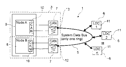
In Figure 1, a bus architecture 1 which comprises a central processing unit
3, a data line 5 and bus users 6 is shown diagrammatically. In the bus
architecture 1, the central processing unit 3 operates as a "master"
whereas the individual bus users 6 act as "slaves".
The central processing unit 3 has two bus interfaces 7 which are connected
to the transceiver units 8 and 9 via one bus control unit 10 in each case.
The bus users 6 are successively also connected to the data line 5 via a
bus interface, not drawn. The data line 5 is constructed to be ring-shaped,
a first end 12 of the data line 5 being connected to the transceiver unit 8
via
the associated bus interface 7 and a second end 13 of the data line 5 being
connected to the other transceiver unit 9 via the corresponding bus
interface 7. The two transceiver units 8 and 9, respectively, alternately
operate as transmitter and as receiver. In this arrangement, the data for the
data line 5 are coded for the data line 5 or decoded for the transceiver units
8 and 9, respectively, by means of the bus control units 10; the bus
interfaces 7 are used for level matching of the data to be exchanged. Both
the bus control units 10 and the bus interfaces 7 operate in both directions.
Figure 2 shows a modern passenger plane 15 in a side view, the cockpit
16, the tailfin 17 and the engines 18 of which can be clearly seen. Such an
aircraft 15 has a row of passenger doors 20 and freight doors 22 on both
sides. Both the passenger doors 20 and the freight doors 22 are provided
with local door controllers (LDC) 11 which are linked into the bus
architecture 1
according to Figure 1 as bus users 6.
To achieve a sufficiently rapid data exchange between the central
processing unit and the local door controls, the right-hand door controls
arranged on the right-side of the aircraft 15 and the left-hand door controls
arranged on the left-hand side of the aircraft 15 are in each case connected
to their own data line. This can be seen in Figure 3 which diagrammatically
shows a further bus architecture 23 for separately driving the right-hand
and left-hand door controls of the aircraft 15 shown. The central processing
unit 3 can be seen which is connected to a right-hand data line 25 and to a
left-hand data line 26 via bus interfaces 7. The local door controls 28
arranged on the right-hand side of the aircraft 15 are connected as bus
users 6 to the right-hand data line 25. The left-hand door controls 29
CA 02547502 2006-05-23
- 8 -
arranged on the left-hand side of the aircraft 15 are connected as bus
users 6 to the left-hand data line 26.
The central processing unit 3 correspondingly has a total of four transceiver
units 8, 9, 31 and 32, respectively. In this arrangement, the transceiver
units 8 and 9 are used for sending and for receiving, respectively, data in or
from the right-hand data line 25, respectively. The transceiver units 31 and
32, respectively, are correspondingly allocated to the left-hand data line 26.
Figure 4 diagrammatically shows the structure of a bus user 6. The bus
user 6 has a bus interface 7 for connection to the data line 5 for level
matching. Two transceiver units 40 and 41 are connected to the bus
interface 7. A bus control unit 10 is in each case interposed for coding and
decoding, respectively, the data to be exchanged. The transceiver unit 40
has a memory chip 44 and a processor 45. The transceiver device 41
comprises a hardware chip 46. The transceiver unit 40 can monitor the
transmit data of the transceiver unit 41 via the common transmit line 47.
The transceiver unit 41 shares the associated bus control unit 10 with a
monitoring unit 43 which is connected to the bus interface 7. The
monitoring unit 43 only activates the transmit activity of the bus interface 7
when a correspondingly allocated synchronization message is received via
the data line 5. Otherwise, the bus interface 7 is only activated for
reception.
If the software-based transceiver unit 40 detects an error in the output data
of the transceiver unit 41, a control signal is generated which is supplied to
the connection between the monitoring unit 43 and the bus interface 7 via
the signal output 50 and a logic chip 52 in the form of AND operation. The
result is that the bus interface 7 is activated for sending only when the
transceiver unit 40 is enabled.
At a predetermined time, a corresponding data packet which contains a
synchronization message and an addressing message is available for the
bus user 6 shown. The monitoring unit 43 detects the synchronization
message and the addressing message and recognizes that the following
data packet is addressed to its own bus user 6. The bus interface 7 is
thereupon activated to send. The transceiver unit 40 and the transceiver
unit 41 respond to the data sent to them and send their output data via the
CA 02547502 2006-05-23
- 9 -
bus interface 7 into the data line 5. In particular, the transceiver unit 40
sends the data written into the memory chip 45 during the passive sending
time by means of the processor 44. The processor 44 is constructed, for
example, as a local door control which processes data from numerous
actuators and sensors and provides data via the memory chip 45. This
makes it possible to interrogate the door status which is of importance to
the safety of the aircraft.
The monitoring function of the transceiver unit 40 with regard to the
transmit data of the transceiver unit 41 ensures additional safety.
Furthermore, the monitoring unit 43 ensures that no unnecessary or even
falsely generated data volumes pass into the data line 5 since it activates
the bus interface 7 for sending only for a certain time. Whereas a transmit
unit which has failed as "babbling idiot" blocks the data line 5 due to the
volumes of meaningless data in a usual bus architecture, data are only
sent into the data line 5 for the open period of time of the transmit activity
of
the interface 7 in the present case if the processor 43 operates incorrectly
as "babbling idiot". The receiving transceiver unit 8 and 9, respectively, of
the associated central processing unit 3 detects these "meaningless" data
and can take countermeasures since the faulty bus user can be inferred
from the time correlation. The bus architecture as a whole remains
operable.
Figure 5 shows the time variation of the data exchange within the bus
architecture described. It shows the data exchange for a cycle time 55 in
the ring-shaped data line. Data packets 57 and 58 intended for the
respective bus users are sent successively into the ring-shaped data line
with a clock time 56. The data packets 57 are intended in this case for local
door controls arranged on the right-hand side of an aircraft whereas the
data packets 58 are allocated to the left-hand door controls arranged on
the left-hand side of an aircraft.
All data packets 57 and 58 are successively sent once within a cycle time
55. This determinism makes it possible to correlate errors occurring within
the data packets 57 and 58 with a respective local door control.
The structure of one of the data packets 57 or 58, respectively, shown
within the clock time 56 can be found in Figure 6 in detail. To clarify, the
cycle time 55 and the individual data packets 58 are again shown as
CA 02547502 2006-05-23
- 10 -
section from Figure 5. The clock time 56 is shown additionally spread out.
Within the clock time 56, the data packet 58 located in the data line
comprises a preceding information signal 59 generated by the central
processing unit which contains a synchronization message 60 and an
addressing message 61. After receiving the synchronization message 60
and the addressing message 61, the monitoring unit 43 shown in Figure 4
switches the bus interface allocated to the bus user to be active for sending
so that the corresponding local door control sends its transmit data 63 into
the data line. After a predetermined time which corresponds to the clock
time 56, the transmit function of the corresponding interface is deactivated.
In the period of time shown by the arrows 64, the specific local door control
or the specific bus user, respectively, does not send any data into the data
line. These periods of time are available to the other bus users.
CA 02547502 2006-05-23
-11 -
List of reference designations
Time
1 Bus architecture
3 Central processing unit
5 Data line
6 Bus user
7 Bus interface
8, 9 Transceiver unit (central processing unit)
10 Bus control unit
11 Door controls
12 First end
13 Second end
Aircraft
15 16 Cockpit
17 Tailfin
18 Engines
Passenger doors
22 Freight doors
20 23 Bus architecture
Right-hand data line
26 Left-hand data line
28 Door controls, right
29 Door controls, left
25 31, 32 Transceiver unit (central processing unit)
40, 41 Transceiver unit (bus user)
43 Monitoring unit
44 Memory chip
45 Processor
46 Hardware chip
47 Transmit line
48 Receive line
50 Signal output
52 Logic chip
55 Cycle time
56 Clock time
57 Data packet, left-hand door controls
58 Data packet, right-hand door controls
59 Information signal
CA 02547502 2006-05-23
- 12 -
60 Synchronization message
61 Addressing message
63 Transmit data
64 Period of time