Note: Descriptions are shown in the official language in which they were submitted.
CA 02547638 2006-05-29
WO 2005/058580 PCT/KR2004/003341
ARRANGEMENT AND METHOD FOR MANUFACTURING PET BOTTLE WITH
HANDLE FORMED AT BODY PART BY INJECTION BLOW MOLDING, AND
PET BOTTLE MANUFACTURED BY THEM
[Technical Field]
The present invention relates to a method for
manufacturing a polyethylene terephthalate (which will be
referred to as "PET") bottle having a handle formed on a
body and a PET bottle manufactured thereby, and, more
particularly, to arrangement and method for manufacturing' a
l0 PET bottle having a handle formed on a body through a
continuous process by an injection blow molding method, and
a PET bottle manufactured thereby.
[Background Art]
Tn general, thermal plasticity is a measure of the
l5 ability of a material, such as plastics, to be softened or
melted by heating so that, when the softened or melted
material is pushed into the mold or compressed against a
inner wall of the mold, the material can be variously
changed in shape according to the shape of a mold, and then
20 to be solidified when the material is cooled.
Methods of manufacturing a bottle by taking advantage
of the thermal plasticity of plastics include a blow
molding method, which is mainly used for manufacturing
hollow products, such as a bottle. Basically, the blow
~5 molding method comprises pre-molding a (test tube-shaped)
resin pipe at an appropriate temperature, what is referred
to as a parison or preform, through extrusion or injection,
inserting the parison into a mold having a cavity formed
therein, and blowing air into the preform to expand the
30 parison into a shape corresponding to the shape of the
cavity. Sueh blow molding methods are generally applied to
CA 02547638 2006-05-29
WO 2005/058580 PCT/KR2004/003341
thermoplastic resins, and include an extrusion or direct
blow molding method,. an injection blow molding method, a
stretch blow molding method, and the like. In
manufacturing of the PET bottles, the injection stretch
blow molding method has been widely used
The extrusion blow molding method is a molding method
in which a blowing operation is performed after extruding
melted resin using an extruder, and, more specifically,
comprises forming a pipe-shaped parison using a
thermoplastic resin supplied from a hopper and then melted
within an extrusion screw, blowing the parison to be
expanded to a predetermined shape within a mold, cooling the
parison having the predetermined shape to provide a desired
product of a predetermined shape, and ejecting the product
from the mold.
The extrusion blow molding method has advantages in
that it is possible to form a container having a large
volume, and a container having a handle, and in that it can
be applied to molding of most plastic materials, such as
polyethylene (PE), polypropylene (PP), polyvinyl chloride
(PVC), and the like. However, the extrusion blow molding
method has a disadvantage in that it cannot be applied to
PET materials having~a property of low melt strength.
In order to allow the extrusion blow molding method to
be applied to such PET materials, a modified PET resin is
often used, but it is more expensive than typical PET resins
while having fewer applications than stretched PET resin.
Meanwhile, the injection blow molding is a molding
method combining an injection molding and the blow molding
method, and, unlike the extruding step for the parison in
the extrusion blow molding method, it comprises injecting a
parison or a preform stick into an injection mold, and
blowing the parison in a blow mold.
As described above, in the case of the PET resin with
the low melt strength, since it is difficult to apply the
G
CA 02547638 2006-05-29
WO 2005/058580 PCT/KR2004/003341
extrusion blow molding method thereto due to a draw down
phenomenon on the parison, the injection blow molding method
which does not cause the draw down phenomenon on the parison
is usually used in the art. In particular, in the case of
the PET resin, the injection stretch blow molding method is
mainly applied, which bi-axially stretches a parison
longitudinally by means of a stretch rod while blowing the
parison within the blow mold.
When producing the containers having the handle formed
on the body by means of the extrusion blow molding method,
since a portion corresponding to the handle must be
compressed together. with rest portions of the parison during
a process of compressing the parison between mold halves,
the parison must be extruded to a pipe shape having a large
diameter. Moreover, since the parison must be expanded to a
predetermined shape corresponding to that of a cavity in the
mold as soon as the parison is extruded to the pipe shape,
operations such as temperature treatment and the like cannot
be smoothly performed, thereby making it difficult to
manufacture a container having a uniform thickness.
Moreover, since the mold asymmetrically surrounds the
parison, it is difficult to manufacture a container having a
uniform thickness, and there is an increase of unnecessary
portions, which must be removed after ejection of products
35 from the mold.
In comparison to the extrusion blow molding method,
the injection blow molding method has advantages in that it
can provide a molded product with even distribution of the
material in the product while having uniformity in weight,
volume and thickness of the product, and in that a design
molding of a neck requiring accuracy is possible. However,
there are disadvantages in that it is necessary to provide a
highly advanced technology, especially, in manufacturing a
mold and in a molding method, and to install two.types of
mold. Moreover, unlike the extrusion blow molding method,
3
CA 02547638 2006-05-29
WO 2005/058580 PCT/KR2004/003341
there is a problem in that the injection blow molding method
cannot form the container having the handle formed on the
body.
[Disclosure]
[Technical Problem]
Therefore, the present invention has been made in
view of the above problems, and it is an object of the
present invention to provide arrangement and method for
manufacturing a PET bottle having a handle formed on a body
through an injection blow molding method, designed to allow
the PET bottle having the handle formed on the body, which
cannot be manufactured by the conventional injection blow
molding method, to be manufactured in such a manner that
the handle is formed on the body during a process of
blowing, as with an extrusion blow molding method, and a
PET bottle manufactured thereby.
[Technical Solution]
In accordance with an aspect of the present invention,
the above and other objects can be accomplished by the
provision of an arrangement for manufacturing a PET bottle
having a handle formed on a body, comprising: a preform
blow mold for blowing air into a preform to expand the
preform in a predetermined ratio to a complete shape so as
to allow a handle section to be compressed; a blow mold
having a handle forming portion for compressing both sides
of the bottle to form the handle section; a cutting
apparatus including a mold punch for cutting off the
compressed portion of the handle section compressed by the
handle forming portion; a bonding apparatus for bonding the
compressed portion of the handle section compressed by the
handle forming portion or a cut-off portion remaining in
4
CA 02547638 2006-05-29
WO 2005/058580 PCT/KR2004/003341
the handle section after cutting off the compressed portion
of the handle section by the cutting apparatus; and a
conveyer for conveying the preform or the molded PET bottle
while clamping a neck of the preform or a neck of the
molded PET bottle.
In accordance with another aspect of the present
invention, a method of manufacturing a PET bottle having a
handle formed on a body is provided, comprising the steps
of: a) performing a first blowing 'operation to blow
compressed air into a test tube-shaped preform in order to
form a first hollow PET container after heating the test
tube-shaped preform manufactured by injection molding and
conveying the preform to a preform blow mold; b) performing
a second blowing operation to blow compressed air into the
first PET container in order to form a second PET container
having a handle section formed thereon after conveying the
first PET container to a blow mold having a handle forming
portion; c) cutting off a compressed portion of the second
PET container using a mold punch in a cutting mold for
cutting off the compressed portion of the handle section in
order to form a third PET container after conveying the
second PET container to the cutting mold; and d) injection
molding a cut-off portion in the handle section of the
third PET container remaining after the step c) into a
predetermined shape in order to form a fourth PET container
after conveying the third PET container to an insert
injection mold for injection molding the cut-off portion of
the handle section remaining after the step c).
In accordance with yet another aspect of the present
invention, a PET bottle manufactured by the arrangement or
the method as described above is provided.
[Description of Drawings
The above and other objects, features and other
5
CA 02547638 2006-05-29
WO 2005/058580 PCT/KR2004/003341
advantages of the present invention will be more clearly
understood from the following detailed description taken in
conjunction with the accompanying drawings, in which:
Figs. 1 to 3 are cross-sectional views illustrating a
conventional process of manufacturing a preform by means of
an injection molding method;
Fig. 4 is a perspective view illustrating an overall
construction of an arrangement for manufacturing a PET
bottle having a handle formed on a body through an
injection blow molding method in accordance with the
present invention;
Fig. 5 is a top view illustrating the arrangement
shown in Fig. 4;
Figs. 6 to 10 are perspective views illustrating
products obtained at respective steps during an injection
blow molding process for forming a PET bottle having a
handle formed on a body in accordance with Embodiment 1 of
the present invention;
Figs. 11 to 15 are schematic perspective views
illustrating apparatuses used for the respective steps
during the injection blow molding process for forming the
PET bottle having the handle formed on the body in
accordance with Embodiment l of the present invention;
Figs. 16 and 17 are perspective views illustrating
products obtained by the third step and the fourth step of
a method in accordance with Embodiment 2 of the present
invention; and
Fig. 18 is a perspective view illustrating products
obtained by the fifth step of ' a method in accordance with
Embodiment 3 of the present invention.
(Best Model
Reference will now be made in detail. to the
embodiments of the present invention with reference to the
6
CA 02547638 2006-05-29
WO 2005/058580 PCT/KR2004/003341
accompanying drawings, wherein like components will be
denoted by like reference numerals throughout the drawings.
Embodiment 1
Figs. 1 to 3 are cross-sectional views illustrating a
conventional process of manufacturing a preform by means of
injection molding.
As descried above, for forming a PET bottle having a
handle formed on a body through an injection blow molding
method (more preferably, an injection stretch blow molding
method), first, a test tube-shaped preform 10 is formed. As
shown in the drawings,. the preform 10 is formed to a test
tube shape by injecting resin around a core mold 5 by a
cavity mold 3, which is an injection mold. At this time,
the injection mold has a gap formed between the core mold 5
and the cavity mold 3 for forming the test-tube shaped
preform 10, so that the resin is poured into the gap through
a gate 3a of the cavity mold 3, and fills the gap, thereby
forming the preform 10. The core mold 5 is formed at an
upper portion with a neck mold 4, which is divided into two
parts 4a and 4b, and forms an entrance of the bottle. The
molded preform 10 is separated from the cavity mold 3 and
the core mold 5. The preform 10 separated from the core
mold 4 is shown in Fig. 3.
Fig. 4 is a perspective view illustrating an overall
construction of an arrangement for manufacturing a PET
bottle having a handle formed on a body through an
injection blow molding method in accordance with the
present invention, and Fig. 5 is a top view illustrating
the arrangement shown in Fig. 4.
3.0 Referring to Figs. 4 and 5, the arrangement 100 for
manufacturing the PET bottle through the injection blow
molding method in accordance with the invention comprises a
preform heating box 21 to receive and heat a plurality of
preforms 10, a robot arm 23 to deliver the heated preforms
10 from the preform heating box 21, a rotational circular
7
CA 02547638 2006-05-29
WO 2005/058580 PCT/KR2004/003341
plate 20 to receive the heated preforms 10 from the robot
arm 23 and to convey the preforms to respective stages of a
process for manufacturing the PET bottle, a preform blow
mold 40, a blow mold 50 having a handle forming portion, a
cutting mold 60 having a mold punch as a cutting apparatus,
and an insert injection mold 70 as a bonding apparatus, in
which the preform blow mold 40, the blow mold 50, the
cutting mold 60, and the insert injection mold 70 are
located below the rotational circular plate 20, and spaced
a predetermined distance from each other on a supporting
die 25 such that a continuous process can be performed by
rotation of the rotational circular plate 20. Additionally,
the arrangement is provided at the sides of the supporting
die 25 with a series of auxiliary apparatuses, such as an
injector 72, a conveyor 80 to convey a completed PET
container 19, and the like. In particular, the cutting
mold 60 is formed at the side surface thereof with a hole
62 into which the mold punch 61 (see Figs. 14a to 14c) is
inserted. The injector 72 is located at the side of the
insert injection mold 70. Although the construction of the
arrangement shown in Figs. 4 and 5 is based on a blow
molding method adopting a two-stage type injection blow
molding, it is needless to say that the present invention
is applicable to one-stage type injection blow molding.
The process of manufacturing the PET bottle having
the handle formed on the body by means of the injection
blow molding apparatus in accordance with the invention
shown in Figs. 4 and 5 will be described for respective
steps thereof as follows.
Figs. 6 to 10 are perspective views sequentially
illustrating products obtained 'at the respective steps
during the injection blow molding process for forming the
PET bottle having the handle formed on the body in
accordance with Embodiment 1 of the present invention, in
each of which (a) is a perspective view of the products
d
CA 02547638 2006-05-29
WO 2005/058580 PCT/KR2004/003341
formed at the respective steps, and (b) is a perspective
view of a lower portion of the products cut off from a
middle portion thereof.
Figs. 11 to 15 are schematic perspective views
illustrating apparatuses used in the respective steps
during the injection blow molding process for forming the
PET bottle having the handle formed on the body in
accordance with Embodiment l of the invention.
(1) The first step
Referring to Figs. 4 and 5, after being received and
heated within the preform heating box 21, a plurality of
preforms 10 are sequentially clamped, and delivered one by
one by means of the robot arm 23 to the rotational circular
plate 20 such that the heated preforms are mounted to a
predetermined position under the bottom of the rotational
circular plate 20. Then, the rotational circular plate 20
rotates to a predetermined angle, and places an associated
preform 10 mounted under the rotational circular plate 20
to the preform blow mold 40 in order to perform a first
blowing operation of the present invention. In the preform
blow mold 40 (see Fig. 11), compressed air is blown into
the preform 10, while a stretching rod (not shown)
stretches the preform 10 from a preform holder 24 holding
the preform 10. In the present embodiment, although the
injection stretch blow molding method is illustrated as
being used for manufacturing the PET bottle, the present
invention is not limited to this method, and it is apparent
that the injection blow molding method may also be employed.
By such a first blowing operation, a first PET
container 13 as shown in Fig. 7 is formed, in which the
first PET container 13 has an elliptical hollow portion 13a
formed at the center thereof (see Fig. 7). This is for the
purpose of providing an appropriate shape for forming a
handle section on the PET bottle through a series of
molding processes described hereinafter. However, it
5
CA 02547638 2006-05-29
WO 2005/058580 PCT/KR2004/003341
should be understood that the present invention is not
limited to the elliptical shape as mentioned above. Fig.
12 shows the first PET container 13 produced after the
first blowing operation.
In accordance with the present embodiment, since the
PET bottle has therein the elliptical hollow portion, which
has directionality in a circumferential direction, and the
handle is also disposed at one portion of the PET bottle,
it is desirable that, when mounting the preform 10 on the
blow molds 40, 50, 60 and 70 of the present invention, the
preform 10 on the blow molds 40, 50, 60 and 70 are mounted
in the same direction. This can be achieved by fixing the
direction of the PET bottle mounted under the rotational
circular plate 20. As one example, a groove (not shown)
may be formed on a predetermined position of a neck of the
preform 10 so as to allow the groove formed on the neck of
the preform 10 to be caught by a predetermined portion
under the bottom of the rotational circular plate 20 when
the rotational circular plate 20 clamps the preform 10, so
that the PET bottle is prevented from rotating under the
bottom of the rotational circular plate 20, thereby
allowing the preform 10 of the PET bottle to be accurately
located into the respective blow molds.
Meanwhile, when forming the preform 10 having a
circular hollow portion as shown in Fig. 6 into the first
PET container 13 having the elliptical hollow portion as
described above (see Fig. 7), the preform must be formed to
have a uniform thickness. As one method of achieving this
purpose, there is a method of creating a temperature
variation in the circumferential (rotational) direction of
the preform by heating an outer peripheral portion of the
preform corresponding to a minor axis of an ellipsoid of
the first PET container 13 after blow molding the preform
higher than an outer peripheral portion of the preform
corresponding to a major axis of the ellipsoid of the first
CA 02547638 2006-05-29
WO 2005/058580 PCT/KR2004/003341
PET container 13 after blow molding the preform, such that
the outer peripheral portion of the preform corresponding
to the minor axis of the ellipsoid is extended more than
the outer peripheral portion of the preform corresponding
to the major axis of the ellipsoid, thereby allowing the
hollow portion of the first PET container to have the
elliptical shape having the uniform thickness.
It is desirable that, when forming the first PET
container 13 in the first blowing operation, the first PET
container 13 is formed to 60 80 0 of the volume of a
completed PET bottle design. Additionally, for preventing
the product from being cooled upon a second blowing
operation, which follows the first blowing operation, the
temperature of the first blow mold 40 must be appropriately
controlled.
(2) The second step
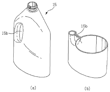
Next, a second blowing operation is performed to form
a second PET container 15 as shown in Fig. 8 after mounting
the first elliptical PET container 13 formed by the first
blowing operation to the blow mold 50 having the handle
forming portion. During the second blowing operation, both ,,
sides of a predetermined portion of a body of the first
elliptical PET container 13 formed by the first blow
molding are compressed by molding protrusions 51, formed on
inner surfaces of mold halves to act as the handle forming
portion for forming the handle section on the first PET
container 13, while the remainder of the body of the first
PET container 13 is secondarily stretched by blowing. Fig.
13 shows the second PET container 15 ejected after the
second blowing operation. With this second blowing
operation, the body of the second PET container 15 is
formed into the completed PET bottle design.
Meanwhile, the first elliptical PET container 13
primarily stretched in the first blowing operation is thin,
and Vulnerable to variation in outer temperature. In
11
CA 02547638 2006-05-29
WO 2005/058580 PCT/KR2004/003341
particular, considering that the handle section is
compressed by the mold piece 51, and thus suffers from a
cooling phenomenon causing the temperature to be rapidly
decreased, the blow mold 50 having the handle forming
portion must be appropriately controlled in temperature.
Additionally, since the second blowing operation is
continuously performed after primarily stretching the first
PET container, and the stretchability of the first PET
container is different from that of the preform 10, the
temperature and the blowing pressure for the primarily
stretched container must be changed.
Additionally, for ensuring that, after a compressed
portion 15b of the handle section of the second PET
container 15 is cut off in a process described hereinafter,
ends 17c (see Fig. 9) of a cut-off portion remaining in the
handle section are bonded to an insert injection portion
19c (see Fig. 10) formed through an insert injection
process, which is a bonding process, each of the molding
protrusions 51 (see Fig. 13) is preferably formed on the
surface thereof with irregularities, which cause the ends
17c (see Fig. 15) of the cut-off portion remaining in the
handle section to be slightly widened from each other.
(3) The third step
Next, when the second PET container 15 is provided by
the second blowing operation, the second PET container 15
is formed at one portion thereof with the handle section of
a depressed and raised feature, which will be formed to the
handle upon completion of manufacturing the PET bottle.
That- is, since the compressed portion 15b ( see Fig . 8 ) of
the handle section is not completely separated, it must be
removed by cutting. For this purpose, after the second PET
container 15 is conveyed to the cutting mold 60 as shown in
Fig. 14, the third step of the present invention will be
performed. For reference, in (a) to (c) of Fig. 19, (a) is
a perspective view illustrating an overall construction of
12
CA 02547638 2006-05-29
WO 2005/058580 PCT/KR2004/003341
the cutting mold 60, (b) is a horizontal sectional view of
the cutting mold 60 shown in (a) of Fig. 14, and (c) is a
longitudinal sectional view thereof.
With the second PET container 15 as shown in Fig. 8
equipped to the cutting mold 60, as a hydraulic pressure
cylinder 63 equipped at the side surface of the cutting
mold 60 applies force to the mold punch 61 inserted into a
through-hole formed at the side surface of the cutting mold
60, the mold punch 61 is pushed into the compressed portion
15b of the handle section, and cuts off the compressed
portion 15b, thereby forming a third PET containex 17.
Then, the compressed portion 15b of the handle section is
ejected through the mold piece 60a at one side of the
cutting mold 60 by the mold punch 61, and is then recycled.
In Fig. 9, reference numerals 17a and 17b denote containing
spaces defined in the third PET container 17, respectively.
Meanwhile, in the case where the second PET container
15 has a thick wall, it is effective to install a heater
61a separately to an end of the mold punch 61. At this
time, the temperature of the heater 61a is preferably in
the range of X60 ~ 300 ~C, and must be appropriately
controlled to prevent the formation of yarns or threads.
Moreover, in order to prevent crystallization around the
cut portion, it is desirable that the cutting process is
performed as quickly as possible. After the cutting
process, the ends 17c of the cut-off portion remaining in
the handle section after cutting off the compressed portion
may be partially widened.
When the compressed portion of the handle section is
cut off by means of the mold punch 61 while being heated by
the heater 61a equipped to the end of the mold punch 61,
the cut-off portion can be slightly melted by the heat of
the heater 61a, and becomes blunt, thereby forming a non
crystallized portion (see 17c of Fig. 15). The non
crystallized portion serves to enhance bonding efficiency
13
CA 02547638 2006-05-29
WO 2005/058580 PCT/KR2004/003341
with another PET part, which will be introduced during an
insert injection process described below.
(4) The fourth step
Meanwhile, it would seem possible that the ends of
the cut-off portion remaining in the handle section can be
bonded to each other by heating and compressing the cut-off
portion remaining in the handle section after the cutting
process using the mold punch 61. However, since the PET
material stretched by the blowing process has a fixed
molecular orientation, it is difficult to bond the PET
material by heating and compressing. Additionally, even if
bonding is performed in such a way, the bonding strength is
insufficient to permit the completed bottle to be filled
with certain items, such as liquid. Accordingly, in order
to ensure satisfactory bonding effects, instead of bonding
the ends of the cut-off portion remaining in the handle
section by compressing both sides of the cut-off portion
simultaneously with the cutting process in the third step,
it is desirable to perfarm a bonding process for the cut-
off portion remaining in the handle section in the fourth
step after the cutting process in the third step.
As for the bonding process for the cut-off portion
remaining in the handle section after the cutting process,
the fourth step is performed after the third PET container
17 with the compressed portion 15b removed from the handle
section, as shown in Fig. 9, is conveyed to the insert
injection mold 70, acting as the bonding apparatus, as
shown in Fig. 15.
For reference, in Fig. 15, (a) is a horizontal
sectional view illustrating the insert injection mohd 70,
(b) is a longitudinal sectional view thereof, and (c) is an
enlarged view of part A, where insert injection molding is
performed in a state that insert injection mold halves 70
are engaged with each other.
As shown -in the drawings, in the fourth step of the
14
CA 02547638 2006-05-29
WO 2005/058580 PCT/KR2004/003341
present invention, with the injector 72 located at the side
of the insert injection mold 70, injection molding is
performed by means of the injector 72 along a cutting line
on the ends 17c. (see Fig. 9) of the cut-off portion
remaining in the handle section of the third PET container
17.
When the third PET container 17 is mounted in the
insert injection mold 70, both sides of an intermediate
portion 17d of the cut-off portion remaining in the handle
section are compressed by a predetermined portion 71 (see
Fig. 1S), acting as a compressing member, of the insert
injection mold 70, thereby preventing a sealing material
from being leaked through a gap between the intermediate
portions 17d into the space 17b upon insert injection
molding. At the same time, the ends 17c of the handle
section of the third PET container 17 are sealed through
insert injection molding. That is, spaces a and b shown in
Fig. 15 are filled with the sealing material, thereby
providing an inner circumference of a handle section 19d
~0 with a smooth and volumetric shape, so that when a user
grips the handle of the PET bottle, the inner circumference
of the handle section 19d provides a convenient grip for
the PET bottle. At this time, the dimensions of an insert
injection molded part 19c are determined to maintain a
constant strength according to thickness and shape of the
bottle so as to provide an assistant function in
strengthening of the handle section.
The fourth PET container 19 molded by the insert
injection mold 70 has the insert injection molded part 19c
formed around the ends 17c of the cut-off portion remaining
in the handle section of the third PET container 17 after
the cutting process, and is a completed PET bottle.
Meanwhile, as for another bonding process for the
cut-off portion remaining in the handle section after the
3S cutting process, the fourth step may be performed by means
CA 02547638 2006-05-29
WO 2005/058580 PCT/KR2004/003341
of ultrasonic bonding instead of insert injection molding.
Ultrasonic bonding is a method of welding overlapping
portions of the plastic to each other after generating heat
on the overlapping portions by means of ultrasonic
vibration, and is applicable not only o bonding of a thin
material but also to bonding a thick plastic material. In
particular, in the case of the PET materials, it is
impossible or difficult to apply heat plat bonding, impulse
bonding or high frequency bonding to bonding of the PET
materials, whereas the ultrasonic bonding can be applied
thereto by use of the high frequency oscillator, vibrator,
tool horn, and the like.
As with the bonding process using the insert
injection mold as described above, with both sides of the
intermediate portion 17d (see Fig. 9) of the handle section
of the third PET container 17 compressed, high frequency
vibration is generated on the overlapping portions, so that
the overlapping portions are heated and welded to each
other.
Embodiment 2
According to Embodiment 1, the method of manufacturing
the PET bottle comprises the steps .of performing the first
blowing operation to blow compressed air into the preform
10 in the preform blow mold 40 in order to form the first
hollow PET container 13 (the first step); performing the
second blowing operation to blow compressed air into the
first PET container 13 in order to form the second PET
container 15 in the blow mold 50 having the molding
protrusions 51 (the second step); cutting off the
compressed portion 15b of the second PET container 15 in
order to form the third PET container 17 (the third step);
and bonding the ends l7c remaining in the handle section of
the third PET container 17 in order to form the fourth PET
container (when bonding is performed during insert
l6
CA 02547638 2006-05-29
WO 2005/058580 PCT/KR2004/003341
injection molding, the fourth PET container has the shape
shown in Fig. 10, and when bonding is performed during
ultrasonic bonding, the fourth PET container has a similar
shape shown in Fig. 17) (the fourth step).
Figs. 16 and 17 are perspective views illustrating
products obtained by the third step and the fourth step of
a method in accordance with Embodiment 2 of the present
invention, respectively.
Referring to Figs. 16 and 17, the method according to
Embodiment 2 comprises the same steps as those of the
method according to Embodiment 1, except for the sequence
of the third step and the fourth step (more specifically,
the ultrasonic bonding process) of Embodiment 1. That is,
in the third step of the method according to Embodiment 2,
both sides of the compressed portion 15b in the handle
section of the second PET container 15 shown in Fig. 8 are
bonded by the ultrasonic bonding process, thereby forming a
third PET container 16 shown in Fig. 16, and in the fourth
step of Embodiment 2, the compressed and bonded portion 16b
of the handle section of the third PET container 16 is cut
off, thereby forming a fourth PET container 18 shown in Fig.
17.
According to Embodiment 2, the second and third steps
of the method may be performed separately. Alternatively,
the second and third steps of the method may be performed
concurrently, by means of the blow mold 50 (see Fig. 13)
having an ultrasonic vibrator (not shown) equipped at the
distal end of one of the molding protrusions 51 of the blow
mold 50 for forming the second PET container 15. In the
latter case, there are effects of reducing the time for
manufacturing the products as well as manufacturing costs.
Embodiment 3
Fig. 18 is a perspective view illustrating. products
obtained by the fifth step of a method in accordance with
17
CA 02547638 2006-05-29
WO 2005/058580 PCT/KR2004/003341
Embodiment 3 of the present invention. Embodiment 3
consists of five steps.
The first step of the method according to Embodiment
3 is the same as that of the first step of the method
according to Embodiments 1 and 2. That is, the first
blowing operation is performed after the preform is mounted
to the preform blow mold 40.
Unlike the second step of the method according to
Embodiments 1 and 2, in the second step of the method
according to Embodiment 3, the first PET container 13 is
not completely expanded to the completed PET bottle design
by the blowing operation. Instead, according to Embodiment
3, the method comprises an additional fifth step for
performing a blowing operation to stretch the PET container
to the completed PET bottle design.
That is, the second step of the method according to
Embodiment 3 is provided by modifying the second step of
the method according to Embodiments 1 and 2, in which the
second blowing operation is performed to form a second PET
container having a shape of 70 ~ 90 % of the volume of the
completed PET bottle design by blowing compressed air into
a first PET container 13 to such an extent that a handle
section of the first PET container 13 is not deformed when
compressing the handle section with the blow mold 50 having
the molding protrusions 51.
In the second step of the method according to
Embodiment 3, although the second PET container (similar to
the PET container shown in Fig. 8)~ is also formed with a
compressed portion 15b of the handle section by compressing
the first PET container 13 expanded to the shape of 60
80 0 of the volume of the completed PET bottle design in
the first step, the second PET container is maintained in a
state of being blown to the shape of 70 ~ 90 0 of the
volume of the completed PET bottle design.
Although the third and fourth steps of the method
18
CA 02547638 2006-05-29
WO 2005/058580 PCT/KR2004/003341
according to Embodiment 3 are the same as those of the
method according to Embodiments 1 or 2, it is desirable
that the operating temperature of the first step is
maintained in the third and fourth steps due to the blowing
operation for forming the PET container into the completed
PET bottle in the fifth step as described below. More
specifically, as with Embodiment l, the compressed portion
15b of the second PET container is cut off in the third
step, and ends 17c of a cut-off portion remaining in the
handle section of the third PET container are bonded by
means of insert injection or the ultrasonic bonding in the
fourth step. Alternatively, as with Embodiment 2, both
sides of the compressed portion 15b are bonded through the
ultrasonic bonding in the third step, and the compressed
portion 16b is cut off in the fourth step.
In the fifth step of the method according to Embodiment 3, an
additional blowing operation is performed to form a fifth PET container 14 as
shown in Fig. 18 after mounting a fourth PET container (similar to the
container as shown in Fig. 10 or in Fig. 17, but in a state of being blown to
0 the shape of 70 ~ 90 d of the volume of the completed PET bottle design) to
a
blow mold (not shown) having a completed PET bottle shape and having a handle
forming portion which will penetrate the body of the PET container in the
fifth step. In comparison with the blow mold 50 having the molding protrusions
51 shown in Fig. 13, the blow mold for the third blowing operation of
~ 5 Embodiment 3 is different from the blow mold 50 in that molding
protrusions
acting as the handle forming portion formed on blow mold halves contact each
other through an opening 19d or 18d of the handle section as shown in Fig. 10
or in Fig. 17. If the blowing process is performed in the fifth step after
finishing the bonding process in the third and fourth steps, an effect of
3 0 providing bonded portion 19c or 18c in Fig. 10 or in Fig. 17 embedded into
the
container is provided. Fig. 18 show the fifth PET container provided by the
fifth step after finishing the bonding process, for example, by means of
insert injection molding, in which the fifth PET container 14 has the insert
injection molded part 19c of Fig. 10 embedded in the container, and the handle
3 5 section has the penetrated shape 14d.
lJ
CA 02547638 2006-05-29
WO 2005/058580 PCT/KR2004/003341
Embodiment 4
Embodiment 4 is provided by combining the second step
of Embodiment 2 in which the second blowing operation is
performed by use of the blow mold 50 having the handle
forming portion, and the third step of Embodiment 2 in
which the compressed portion 15b is bonded by ultrasonic
bonding. Specifically, Embodiment 4 is characterized in
that formation and bonding of a compressed portion 15b in a
handle section are performed at the same time by use of a
handle foaming device including a handle forming portion
and an ultrasonic bonding apparatus installed on the distal
end of the handle forming portion.
In a method of manufacturing a PET bottle having a
handle formed on a body according to Embodiment 4, the
first step is the same as that of Embodiments 1 to 3. That
is, in the first step of the method, the first blowing
operation is performed after mounting the preform 10 on the
preform blow mold 40.
In the second step, the formation and bonding of the
compressed portion 15b of the handle section are performed
concurrently in such a manner that with both sides of a
first PET container compressed, ultrasonic bonding is
performed on the compressed portion 15b at the same time by
use of the handle forming device including the handle
forming portion and the ultrasonic bonding apparatus
installed on the distal end of the handle forming portion.
A second PET container formed by the second step is similar
to the container shown in Fig. 16.
In the third step, a compressed and bonded portion
16b of the handle section is cut off.
In the fourth step, a second blowing operation is
performed after mounting a third PET container (similar to
the container shown in Fig. 17, but in a state. of being
blow molded to the shape of 60 ~ 80 0 of the volume of the
CA 02547638 2006-05-29
WO 2005/058580 PCT/KR2004/003341
completed PET bottle design) to a blow mold (not shown)
having a completed PET bottle shape and having a handle
forming portion which will penetrate the body of the PET
container. In the fourth step, a fourth PET container
having the shape of the completed PET bottle is formed (as
with the PET container as shown in Fig. l8, the fourth PET
container also has the embedded portion 14c, but is
different from the PET container shown in Fig. 1.8 in that
the embedded portion 14c is bonded by ultrasonic bonding).
Although the above embodiments are described with
respect to the PET resin, it is apparent that the present
invention is also applicable to manufacturing of various
bottles using plastic materials other than PET resin.
[Industrial Applicabilitya
As is apparent from the above description, according
to the present invention, the PET bottle having the handle
formed on the body, which cannot be manufactured by
conventional extrusion blow molding methods, is formed by
the continuous injection blow molding method, thereby
providing convenience in use, enhancing efficiency upon
manufacturing the PET bottle having the handle formed on
the body, eliminating labor and costs related to recycling
of the handle made of a different plastic material from
that of the body in the conventional PET container, and
35 preventing environmental pollution and economic loss due to
waste of the handles of the conventional PET container.
Although the injection blow molding method is an
appropriate method for forming the PET bottle having the
handle formed on the body, due to its advantage in that a
container having a uniform thickness can be produced
thereby, it is applicable to the containers made of plastic
materials other than the PET resin, and it is obvious that
the shape of the container is not limited to ellipsoid.
2l
CA 02547638 2006-05-29
WO 2005/058580 PCT/KR2004/003341
Although the preferred embodiments of the present
invention have been disclosed for illustrative purposes,
those skilled in the art will appreciate that various
modifications, additions and substitutions are possible,
without departing from the scope and spirit of the
invention as disclosed in the accompanying claims.
~G