Note: Descriptions are shown in the official language in which they were submitted.
CA 02547984 2006-05-25
Attorney Docket No. 010-121-8015-O 1
ROTOR CORE WITH SPACERS
RELATED APPLICATION DATA
[0001] This application claims priority to co-pending U.S. Provisional Patent
Application
Serial Number 60/689,962 filed on May 27, 2005, the contents of which are
fully incorporated
herein by reference.
BACKGROUND
[0002] The invention relates to a rotor core for electrical machines. More
particularly, the
invention relates to an electric machine that includes a stator core having a
stator core length and
a rotor core having a rotor core length that is greater than the stator core
length.
[0003] Two prior-art motors 10, 15 are shown in Figs. 1-2, The motor 10
includes a stator
core 20 and a rotor core 25 manufactured using the same number of laminations
which are
punched with a single tool (die). Specifically, the tool, such as a
progressive die, simultaneously
punches a stator lamination and a rotor lamination, which is positioned inside
the stator
lamination in order to reduce waste.
[0004] The motor 15 of Fig. 2 includes a stator core 20 and a rotor core 2Sa
that have the
same length. This construction is advantageous from the cost point of view, as
the same number
of laminations is used for both the stator core 20 and the rotor core 25a, The
output of the motor
of Fig. l, which uses the same stator core 20 as in Fig. 2, is improved over
the output of the
motor 15 of Fig. 2 due to the use of a longer rotor core 25 and magnet 30, the
flux of which is
axially concentrated through the stator. As a result, air-gap flux density,
the stator flux linkage,
the machine specific output, and/or efficiency are increased. The major
drawback of this
solution is the increase in cost associated with the need to produce more
rotor laminations than
stator laminations. The increased number ofrotor laminations, as compared to
stator laminations
of Fig. 2, requires the manufacturer to purchase additional laminated steel
and invest in
CA 02547984 2006-05-25
Attorney Docket No. 010121-8015-O 1
supplementary tooling, which can produce rotor laminations alone, rather than
the more common
stator and rotor lamination combination.
[0005] The invention overcomes this disadvantage through special constructions
for which
an increased motor output is achieved by using approximately the same number
of laminations in
the stator core and rator care.
SUMMARY
[0006] In one embodiment, the invention provides an electric machine that
includes a stator
core having a stator core length, a first rotor core portion, and a second
rotor core portion. A
spacer is coupled to the first core portion and the second core portion to at
least partially define a
rotor core that has a rotor core length that is greater than the stator core
length. A permanent
magnet is coupled to the rotor core and has a magnet length. The magnet length
is greater than
the stator core length.
[0007] In another embodiment, the invention provides an electric machine that
includes a
rotor shaft, a quantity of stator laminations stacked adjacent one another to
define a stator core
having a stator core length, and a quantity of rotor laminations coupled to
the rotor shaft. The
quantity of rotor laminations is about equal to the quantity of stator
laminations. A permanent
magnet is coupled to at least one of the rotor laminations and has a magnet
length that is greater
than the stator core length.
[0008) The invention also provides a method of manufacturing a motor. The
method
includes forming a quantity of stator laminations, stacking the quantity of
stator laminations to
define a stator core having a first end and a second end that define a stator
length, and forming a
quantity of rotor laminations. The method also includes stacking the quantity
of rotor
laminations and connecting a spacer to at least one of the rotor laminations
such that the quantity
of rotor laminations and the spacer cooperate to define a rotor core having a
rotor core length.
The method further includes attaching a permanent magnet to the rotor core to
define a rotor.
The permanent magnet has a magnet length that is greater than the stator core
length.
2
CA 02547984 2006-05-25
Attorney Docket No. 010121-8015-O1
[0009] Other aspects and embodiments of the invention will become apparent by
consideration of the detailed description and accompanying drawings.
BRIEF DESCRIPTION OF THE DRAWINGS
[0010] The detailed description particularly refers to the accompanying
figures in which:
[0011] Fig. 1 is a schematic illustration of a longitudinal-sectional view of
a prior art motor
including a stator and a rotor;
[0012] Fig. 2 is a schematic illustration of a longitudinal-sectional view of
another prior art
motor including a stator and a rotor;
[0013] Fig. 3 is a schematic illustration of a longitudinal-sectional view of
a motor including
a stator and a rotor;
[0014] Fig. 4 is a schematic illustration of a longitudinal-sectional view of
a motor including
a stator and a rotor that includes gaps or spaces;
[0015] Fig, 4a is an enlarged schematic illustration of a portion of the motor
of Fig. 4, within
the contour denoted by 4a;
[0016] Fig. 5 is a schematic illustration of a longitudinal-sectional view of
a rotor that
includes a magnetic spacer or extender;
[0017] Fig. 6 is a cross-sectional view of the rotor of Fig. 5;
]0018] Fig. 7 is a schematic illustration of a longitudinal-sectional view of
a motor including
a stator and a rotor that includes a magnetic spacer or extender;
[0019] Fig. 8 is a schematic illustration of a longitudinal-sectional view of
a motor including
a stator and a rotor that includes a non-magnetic spacer;
[0020] Fig. 9 is a schematic illustration of a longitudinal-sectional view of
another motor that
includes a stator and a rotor having end core extensions;
3
CA 02547984 2006-05-25
Attorney Docket No. 010121-8015-O1
[U02I]Fig. 10 is a perspective view
of a spacer;
[0022]Fig. 11 is a perspective view
of another spacer;
[0023]Fig. 12 is a front view of a rotor
lamination; and
[0024]Fig. 13 is a front view of another
rotor lamination.
DETAILED DESCRIPTION
[0025] Before any embodiments of the invention are explained in detail, it is
to be
understood that the invention is not limited in its application to the details
of construction and the
arrangement of components set forth in the following description or
illustrated in the following
figures: The invention is capable of other embodiments and of being practiced
or of being
earned out in various ways. Also, it is to be understood that the phraseology
and terminology
used herein is for the purpose of description and should not be regarded as
limiting. The use of
"including," "comprising," or "having" and variations thereof herein is meant
to encompass the
items listed thereafter and equivalents thereof as well as additional items.
Unless specified or
limited otherwise, the terms "mounted," "connected;" "supported," and
"coupled" and variations
thereof are used broadly and encompass direct and indirect mountings,
connections, supports,
and couplings. Further, "connected" and "coupled" are not restricted to
physical or mechanical
connections or couplings. In addition, where a method, process, or listing of
steps is provided,
the order in which the method, process, or listing ofsteps is presented should
not be read as
limiting the invention in any way.
[0026] Before proceeding, it should be noted that the invention described
herein is especially
suitable for brushless motors with circumferentially placed magnets, a typical
example being the
rotor designs with surface mounted magnets, which are radially magnetized.
However, the
invention can also be adapted for other type of rotors, such as but not
limited to interior
permanent magnet rotors or "spoke" rotors in which the magnets are at least
partially fitted
inside the rotor core.
4
CA 02547984 2006-05-25
Attorney Docket No. 010121-8015-O1
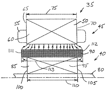
[0027] Fig. 3 illustrates a motor 35 that includes a rotor 40 and ~ stator 45
positioned to
define an air gap therebetween. The stator 45 includes a core 50 that is wound
with one or more
conductors to define coils and windings 55. The core 50 is formed from a stack
of laminations
60 that define a first core end 65 and a second core end 70. A stator core
length 75 is defined as
the length of the core 50 as measured between the first end 65 and the second
end 70.
[0028] The rotor 40 includes a shaft 80 that supports a rotor sore 85. The
rotor core 85 in
turn supports one or more permanent magnets 90, As with the stator core 50,
the rotor core 85 is
formed from a plurality of stacked laminations 95. In preferred constructions,
the rotor core 85
includes about the same number of laminations 95 as the stator core 50 (e.g,,
within about 20
percent). The rotor care 85 includes a first end 100 and a second end 105 that
cooperate to
define a rotor core length 110. In the construction illustrated in Fig. 3, the
rotor core length 110
is about equal to the stator core length 75.
[0029] As illustrated in Fig. 3, the permanent magnet 90 attaches to the outer
periphery of
the rotor laminations 95 and includes a first end 111 that extends beyond the
first end 100 and a
second end 112 that extends beyond the second end 105 of the rotor core 85.
Thus; the
construction of Fig. 3 includes a magnet 90 that defines a magnet length 113,
measured from the
first end 111 to the second end 112, that is greater than the length 75 of the
stator core 50.
However, the rotor core length 110 is substantially the same as the stator
core length 75. Thus,
the magnet 90 overhangs the rotor core 85 and the benefits in increasing the
air-gap flux density
at the stator surface and the stator winding flux linkage are minimal, mainly
due to the increased
reluctance of the end magnetic field path.
[0030] Before proceeding, it should be noted that the magnet length 113, as
well as the stator
core length 75 and the rotor core length 110, are measured from the extreme
axial positions of
the component. Thus, constructions that employ multiple magnets stacked up
along the axial
length still define a magnet length that encompasses all of the magnets. Gaps
between magnets
become part of the magnet length. Similarly, gaps in the stator core 50 or
rotor core 85 would
add to the stator core length 75 and the rotor core length 110.
[0031] Figs. 12 and 13 illustrate two possible laminations 95, 95a for use in
a rotor core 85.
The lamination 95 of Fig. 12 is substantially circular when viewed from the
end and includes
CA 02547984 2006-05-25
Attorney Docket lrlo. 010121-8015-O1
four alignment members 115 and a central aperture 120 for use in attaching the
lamination to the
rotor shaft 80. In most constructions, the central aperture 120 is circular
and is sized to provide
an interference fit between the aperture 120 and the rotor shaft 80. Other
constructions may
employ other shapes or sizes for the aperture 120 as desired.
[0032] The alignment members 115 of Figs. 12 and 13 include rectangular
apertures that are
located approximately 90 degrees apart from one another. The apertures aid in
aligning adjacent
laminations 95 during the stacking process of the rotor core 85. In other
constructions, lances,
indentations, or other features are used as alignment members 115 in place of
the rectangular
apertures. In addition, other quantities or shapes could be employed if
desired. In some
constructions the rotor laminations are welded or bonded together, or other
means known to
those skilled in the art are employed to form a core stack.
[0033] The lamination 95a of Fig. 13 is similar to the lamination 95 of Fig.
12 with the
exception of eight additional weight-reducing apertures 125 that extend
through the lamination
95a. The weight-reducing apertures 125 reduce the weight of the lamination 95a
such that a
rotor core 85 constructed using the laminations 95a of Fig. 13 is
significantly lighter than a rotor
core 85 constructed using the laminations 95 of Fig. 12. Rotor cores 85 can be
constructed using
either the laminations 95, 95a illustrated in Fig. 12 or Fig. 13, or a
combination of these
laminations 95, 95a as desired. In addition, other lamination arrangements not
discussed herein
could be employed if desired.
[0034] Fig. 4 illustrates a motor 130 that improves upon the operational
characteristics of the
motor 35 of Fig. 3. The motor 130 includes three axial rotor core modules 135
approximately
equally spaced on a shaft 140 to at least partially define a rotor core 145.
Each rotor core module
135 is generally assembled from a plurality of laminations 95, 95a similar to
those illustrated in
Figs. 12 or 13. In one construction, a combination of the two illustrated
laminations 95, 95a is
used. Most of the laminations 95, 95a are inner laminations 95a such as the
lamination 95a
illustrated in Fig. 13. Each end of the stack of inner laminations 95a
receives at least one end
lamination 95 that does not include the weight-reducing-holes 125. The use of
end laminations
95 reduces the windage losses of the rotor core modules 135, while the weight-
reducing holes
125 of the inner laminations 95a, reduce the rotor core weight, and thus
reduce mechanical losses.
CA 02547984 2006-05-25
Attorney Docket No. 010121-&015-O1
In other rotor constructions, only one type of lamination, for example
lamination 95a, is
employed. In preferred constructions, the total axial length of the rotor core
modules 135 are
chosen to match the axial length of a stator core 150, thus allowing for the
use of substantially
the same number of laminations for each of the rotor core 145 and the stator
core 150. In some
rotor constructions, such as the construction of Fig. 5, the rotor core
modules 135 are spaced
such that the rotor core end 138 is axially aligned (flushed) with the magnet
end 111 and the
rotor core end 139 is axially aligned with the magnet end 112, respectively.
[0035] As-illustrated in Fig. 4, each of the rotor core modules 135 is coupled
to the rotor
shaft 140 and one or more permanent magnets 155 are attached to the rotor core
modules 135 to
complete a rotor 160. The three rotor core modules 135 are positioned such
that a space or gap
165 is defined between any two adjacent rotor core modules 135. Thus, the
rotor core length
110, including the axial length of each of the core modules 135 and the gaps
165, is greater than
the stator core length 75, while still employing about the same number of
laminations. It should
be noted that a direct connection of each rotor core module to the shaft is
not an absolute
requirement. For example, in some constructions, only one rotor core module is
directly
connected (i.e., in contact with) to the shaft and the other modules are
connected to the module
which is connected to the shaft. Thus, in this example only one rotor core
module is directly
connected to the shaft with the other rotor core module or modules connected
to the first rotor
core module.
[0036] Small rings (not shown) can be placed around the shaft 140 to space the
rotor core
modules 135 at the desired locations. The rings could be built for example
from a non-magnetic
material such as plastic. Additionally, in some constructions the rotor core
modules 135 are
manufactured such that the end laminations flare (bend) towards the exterior,
thereby further
enhancing the axial path of the magnetic flux. Due to the improved axial
distribution of the non-
linear magnetic circuit, the air-gap flux density, the stator flux-linkage,
and motor output are all
increased in comparison with that of the motor 35 of Fig. 3.
[0037] Before proceeding, it should be noted that while the construction
illustrated in Fig. 4
includes three rotor core modules 135, other constructions may employ two
rotor core modules
7
CA 02547984 2006-05-25
Attorney Docket No. 010121-8015-O1
135 or four or more rotor core modules 135. As such, the invention should not
be limited to
constructions that employ three rotor core modules 135.
[0038] To further increase motor performance, a magnetic pacer 170 or extender
may be
positioned between rotor core modules 135 as shown in Figs. 5 and 7. Figs, 10
and 11 illustrate
two possible magnetic extenders 170, 170a that may be employed in a rotor core
145. In
preferred constructions, the magnetic extenders 170, 170a include a
ferromagnetic isotropic
material, with other materials also being suitable for use. The spacer 170 of
Fig. 10 includes a
substantially ring shaped portion 175 that includes an outer diameter 180 that
is substantially
equal to the outer diameter of the rotor laminations 95, 95a, and an inner
diameter 185 selected
to maintain the rotor saturation and mmf drop at a desirable level, while also
reducing the weight
of the spacer 170.
[0039] The spacer 170 also includes four projections 190 that extend from the
ring shaped
portion 175. Two projections 190 extend in each axial direction with the
projections 190
extending in the same direction being spaced about 180 degrees apart. Each of
the proj ections
190 is sized to engage one of the weight-reducing apertures 125 of the
laminations 95, 95a to fix
the position ofthe spacer 170. In other constructions, other arrangements,
quantities, sizes,
and/or shapes maybe employed to define the projections 190.
[0040] The spacer 170a of Fig. 11 is much like the spacer 170 of Fig. 10 but
additionally
includes weight-reducing apertures 195, which extend through the ring shaped
portion 175 and
reduce the weight and inertia of the spacer 170a when compared to the spacer
170 of Fig. 10.
The shape, dimensions and position of the apertures 195 can be the same or
different of that of
apertures 125 from the lamination 9Sa.
[0041] In motors with a relatively high number of poles, the inner diameter
ofthe spacer
170, 170a is substantially larger than the shaft outer diameter. This is
advantageous in reducing
rotor weight and cost: The spacer 170, 170a may be fastened to the rotor core
modules 135 using
bolts or pins 200 such as those shown in Fig. 6. The bolts 200 are at least in
partial contact with
the spacer 170, 170a in order to improve mechanical rigidity of the rotor
assembly 160.
CA 02547984 2006-05-25
Attorney Docket No. 010121-8015-O1
[0042] In a preferred construction, the magnetic spacer 170, 170a is made by
mechanically
pressing or compacting and sintering powder of magnetic iron or soft magnetic
composites.
Materials with isotropic magnetic characteristics are preferable in order to
enhance both the axial
and radial magnetic flux path. To reduce manufacturing cost, the bolts or pins
200 can be formed
as part of the magnetic extender 170, 170a. In some constructions, the
magnetic extenders 170,
170a can be attached to a rotor core comprising laminations 95a by press
fitting the projections
190 through lamination apertures 125.
[0.043] Returning to Figs. 5 and 7, a rotor 205 (shown in Fig. 5) includes two
rotor core
modules 135 that are separated by the spacer 170, 170a. Thus, the rotor 205
defines a rotor core
length 210 that is equal to the axial length of the two rotor core modules 135
plus the axial width
of the spacer 170, 170a. In the illustrated construction, the spacer 170, 1?Oa
is positioned
between two substantially equal length rotor core modules 135. Of course, one
of ordinary skill
will realize that the spacer 170, 170a could be positioned between non-equal
length rotor core
modules 135 and that more core modules and spacers could be employed if
desired.
(0044] A motor 215, illustrated in Fig. 7 includes the rotor 205 of Fig. 5. As
can be seen, the
rotor 205 includes a rotor core 220 as well as a permanent magnet 225 attached
to the rotor core
220. The total axial length of the rotor core plus the magnetic extender 170,
170a is about equal
to the axial length 210 of the magnet 225, which is greater than an axial
length 230 of a stator
core 235.
[0045] Fig. 8 illustrates another motor construction 240 similar to the one
illustrated in Fig.
7. However, rather than positioning the magnetic spacer 170, 170a near the
outside diameter of
the rotor core modules 135 as illustrated in Fig. 7, a non-magnetic spacer 245
is positioned
between the rotor core modules 135 adjacent the rotor shaft 140. This
construction has an
advantage in reducing the forces generated during operation as it positions
the weight of the
spacer 245 nearer to the center of rotation. In addition, light weight and/or
inexpensive material
(e.g., plastic) can be employed to form the spacer 245.
[0046] Fig. 9 illustrates another motor 250 that includes a rotor core 255
that is longer than a
stator core 260, The construction of Fig. 9 includes one laminated rotor core
module 135 and
two magnetic extenders 265. Eaeh of the two end-magnetic extenders 265 engages
the laminated
CA 02547984 2006-05-25
Attorney Docket No. 010121-8015-O1
rotor core module 135 and extends away from the rotor core module 135. The two
magnetic
extenders 265 have the same size and shape and attach through bolts or pins,
or are adhesively
bonded to the end laminations of the laminated core module 135. The end-
magnetic extenders
265 are preferably made out of a material, such as compacted powder of
magnetic iron or soft
magnetic composites, which enhance both the radial and axial flux path and
concentrate the
magnet flux through the stator core 260. In one construction, the magnetic
extenders 265 look
much like the spacers 170, 170a of Fig. 10 but omit the projections 190 on one
side.
[0047] The constructions previously described employ stator and rotor
laminations
manufactured from the same electric steel. It is understood that other
constructions in which the
rotor laminations are produced from material of different thickness and/or
grade than the stator
laminations, although not preferable, are also possible: In this case, the
number of laminations in
the rotor may be different than the number of stator laminations, while the
total length of the
stack of laminations could be the same for the rotor and the stator.
[0048] Thus, the invention provides, among other things, an electrical machine
with
enhanced performance due to the additional length of the rotor core as
compared to the stator
core. Various features and advantages of the invention are set forth in the
following claims.