Note: Descriptions are shown in the official language in which they were submitted.
CA 02548145 2006-06-05
WO 2005/055809 PCT/US2004/040702
[001] NASAL AND ORAL CANNULA SUPPLYING, SAMPLING AND/OR
DETECTING DEVICE
[002] FIELD OF THE INVENTION
[003] This invention relates to a novel cannula which is suitable for use
for both
nasal and oral applications and a method of producing the cannula using
disconnectable mandrel parts to form a mold over or on which the cannula
forming plastics material is applied to form the cannula.
[004] BACKGROUND OF THE INVENTION
[005] This invention relates generally to cannulas adapted for both oral
and
nasal applications for monitoring breathing of a patient, sampling the end
tidal
CO2 content in the exhaled breath of a patient to determine the patient's CO2
blood concentration level, or supplying a treating gas, such as oxygen, to a
patient. In addition, the invention relates to a method of manufacturing a
cannula
adapted to interconnect with both nasal passages and the mouth for use in
monitoring breathing, sampling end tidal CO2, supplying a treating gas and is
especially suitably for the detection of apnea (the absence of breathing).
[006] Nasal cannulas are commonly used to administer a treating gas, such
as
oxygen, to humans having respiratory problems. Illustrations of nasal cannulas
used for this purpose are found in U. S. Patent No. 3,802,431. Nasal cannulas
have been used also for inhalation therapy, made possible by development of
inhalation sensors such as described in U. S. Patent No. 4,745,925. A nasal
cannula can be used to monitor breathing and for detection of apnea when
connected to an inhalation sensor.
[007] Nasal cannulas additionally adapted to communicate with the mouth of
a
patient to permit administration of a gas or sensing of apnea during periods
of
mouth breathing or nasal blockage are also known. Some of these known
cannulas have a single relatively short rigid member, i.e., only extending
about
one half or less of the length of the prong, and the relatively short rigid
member
is glued or otherwise affixed to an exterior surface thereof.
[008] The present invention relates to a novel cannula and method of
manufacturing a cannula having the ability to communicate with both nasal
cavities as well as the mouth or oral cavity of a patient. The method
provides,
CA 02548145 2013-10-04
-2-
in the preferred embodiment, disconnectable mandrels which, when assembled
with one another, form a mold over which a cannula forming polymeric material
is applied, and which, through the capability of each mandrel component being
disconnectable from the other component(s), facilitates removal of the
mandrels
from the formed or manufactured cannula.
[010] SUMMARY OF THE INVENTION
[011] It is an object of the invention to provide a method of manufacturing
a
cannula using an assembly of disconnectable mandrel components over which a
cannula forming plastics or polymeric material is applied. Application of the
plastics or polymeric material over the mandrel assembly and subsequent
extraction of the mandrel components from one another, following sufficient
curing of the plastics or polymeric material, results in a manufactured
cannula
with contiguous internal flow paths for sampling the exhaled breath of a
patient
to detect the end tidal CO2 in the blood of a patient, sensing patient
breathing,
and/or supplying a treating gas.
[012] It is a further object of the invention to provide a multi-part
mandrel
assembly for forming a cannula which facilitates extraction of each of the
mandrel assembly components following at least partial curing the plastics or
polymeric material forming the cannula.
[013] Still another object of the invention is to form the main body of the
mandrel
as two separate, slightly spaced apart components which remain spaced apart
from one another by a small gap or void, during the dipping process, so that
the
gap or void becomes filled with the plastics or polymeric material (e.g. the
plastisol) to form an internal wall, septum or barrier which partitions or
divides the
internal passage of the cannula into two separate compartments or
passageways, one which facilitates either sensing of patient breathing,
monitoring of the end tidal CO2 in a patient's blood stream or supplying a
treating
CA 02548145 2006-06-05
WO 2005/055809 PCT/US2004/040702
-3-
gas while the other of which also facilitates another function, such as,
sensing
of patient breathing, monitoring of the end tidal CO2 in a patient's blood
stream,
and/or supplying a treating gas.
[014] Another object of the invention is to produce a cannula having at
least one
mouthpiece extending from the main body of the cannula to the patient's mouth,
and the cannula is provided with a passageway for supplying a gas to the
patient
via a demand regulator for example, or sampling a patient's oral exhalation
for
monitoring the end tidal CO2 in a patient's blood stream for instance, and
providing the mouthpiece with a retainer passageway for holding a bendable or
flexible dead soft member enabling the mouthpiece to be bent, shaped, molded
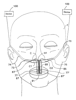
or otherwise reconfigured into a desired curvature or orientation for properly
positioning the opening of the mouthpiece in or adjacent the mouth or oral
cavity
of a patient for detecting or sensing the exhaled breath of the patient.
[015] The present invention relates to a cannula comprising: a hollow main
body having opposed first and second ends with the main body defining an
internal chamber therein; at least a first nasal prong communicating with the
internal chamber of the main body and defining a first nasal prong passageway;
a mouthpiece having a gas passageway and a retainer passageway, and a first
end of the gas passageway communicating with the internal chamber of the main
body while a second free end of the mouthpiece having a gas passageway
opening therein; and an elongate malleable dead soft member being received
within the retainer passageway for facilitating retained adjustment of the
mouthpiece.
[016] The present invention also relates to a method of manufacturing a
nasal
cannula, the method comprising the steps of: assembling a cannula mandrel
assembly comprising separable components with the separable components
including at least one main body forming mandrel, at least one nare forming
mandrel, and at least one mouthpiece forming mandrel; heating the assembled
cannula mandrel assembly to a desired temperature; applying at least one
coating of an uncured cannula forming polymeric material to the cannula
mandrel
assembly to provide a desired material thickness of coating on the cannula
CA 02548145 2006-06-05
WO 2005/055809 PCT/US2004/040702
-4-
mandrel assembly; sufficiently curing the coating applied to the cannula
mandrel
assembly; and disassembling the cannula mandrel assembly and withdrawing
the at least one nare forming mandrel, and mouthpiece forming mandrel and the
main body forming mandrel from the manufactured cannula.
[017] The present invention further relates to a method of using a nasal
cannula
comprising a hollow main body having opposed first and second ends with the
main body defining an internal chamber therein; first and second spaced apart
nasal prongs each communicating with the internal chamber of the main body
and defining respective first and second nasal prong passageways; a
mouthpiece having a first gas passageway and a retainer passageway, and a
first end of the first gas passageway communicating with the internal chamber
of the main body while a second free end of the mouthpiece having a first gas
passageway opening therein; and an elongate malleable dead soft member
being received within the retainer passageway for facilitating retained
adjustment
of the mouthpiece, the method comprising the steps of: inserting the first
nasal
prong in a first nostril of the patient and inserting the second nasal prong
in a
second nostril of the patient; and adjusting a position of the first gas
passageway
opening with respect to a remainder of the cannula, and retaining, via the
shape
retaining member, the adjusted position of the first gas passageway opening.
[018] BRIEF DESCRIPTION OF THE DRAWINGS
[019] The invention will now be described, by way of example, with
reference
to the accompanying drawings, in which:
[020] Fig. 1 is an orthogonal view of a cannula mandrel assembly with the
cannula forming plastics or polymeric material shown in ghost;
[021] Fig. 2 is an orthogonal view of the cannula mandrel parts prior to
assembly;
[022] Fig. 3 is a side elevation of the mouthpiece mandrel of Figs. 1 and 2
showing an end connector;
[023] Fig. 4 is an end section of the end connector taken along section
line 4-4
of Fig. 3;
CA 02548145 2006-06-05
WO 2005/055809 PCT/US2004/040702
-5-
[024] Fig. 5 is a fragmentary side elevation of the main body mandrel of
Figs.
1 and 2 taken along section line 5-5 of Fig. 2;
[025] Fig. 6 is an elevation of the main body mandrel taken in the
direction of
arrow 6 in Fig. 5;
[026] Fig. 7 is a general diagrammatic cross-sectional view of a cannula,
made
by the method of the present invention, taken along section line 7-7 of Fig.
1;
[027] Fig. 8 is a flow diagram of the method of the present invention;
[028] Fig. 9 is an orthogonal view of a cannula mandrel assembly for
forming a
septum or barrier in a void of the main body forming mandrel, with cannula
forming plastics or polymeric material shown in ghost;
[029] Fig. 10A is a front elevational view of the mouthpiece mandrel
showing the
gas passage prong and the retainer prong;
[030] Fig. 10B and 10C are a bottom view and a left side elevational view,
respectively, of the mouthpiece mandrel of Fig. 10A;
[031] Fig. 11 is a diagrammatic perspective view of the cannula formed by a
mandrel assembly having a mouthpiece mandrel;
[032] Fig. 12A and 12B, respectively, are side elevational views showing
the
originally molded orientation of the cannula mouthpiece, relative to a closed
and
an opened mouth of a patient, while Fig. 12C is side elevational view showing
a
retained adjusted orientation of the mouthpiece, relative to an opened mouth
of
a patient, so as to align an opening of the mouthpiece with the patient's oral
inhalation/exhalation path;
[033] Fig. 13 is a front elevational view showing a modification to the
mouthpiece mandrel in which the positions of the gas passage prong and the
retainer prong are reversed;
[034] Fig. 14A is a front elevational view showing a further modification
of the
mouthpiece mandrel;
[035] Fig. 146 is diagrammatic side right elevational view of the
mouthpiece
mandrel of Fig. 14A;
[036] Fig. 14C is diagrammatic top elevational view of the mouthpiece
mandrel
of Fig. 14A;
CA 02548145 2006-06-05
WO 2005/055809 PCT/US2004/040702
-6-
[037] Fig. 14D is a diagrammatic top elevational view, similar to Fig. 14C,
showing a further modification to the mouthpiece mandrel in which the retainer
prong is located on the opposite side of the gas passage prong;
[038] Fig. 15A is a diagrammatic side elevational view of a mandril stub;
[039] Fig. 15B is a diagrammatic right end view of the mandril stub taken
along
section 15B-15B of Fig. 15A;
[040] Fig. 15C is a diagrammatic transverse cross sectional view of a
cannula
manufactured by the mandril stub of Figs. 15A and 15B;
[041] Fig. 15D is a diagrammatic fragmented front elevational view of the
facepiece of a cannula, taken along section, line 15D-15D of Fig. 15C, showing
the formed receiver opening;
[042] Fig. 15E is a diagrammatic transverse cross sectional view of a
completed
cannula manufactured by the mandril stub of Figs. 15A and 15B;
[043] Fig. 15F is a diagrammatic front elevational view of the manufactured
cannula of Fig. 15E;
[044] Fig. 15G is a diagrammatic rear elevational view of the manufactured
cannula of Fig. 15E;
[045] Fig. 16A is a diagrammatic plan view showing a modification to the
mandril
stub prior to attachment to the main body mandrel;
[046] Fig. 16B is a diagrammatic end view of only the mandril stub of Fig.
16A
taken along section 16B-16B of Fig. 16A;
[047] Fig. 16C is a diagrammatic plan view showing of the modified mandril
stub
of Fig. 16A shown assembled with the main body mandrel comprising two
separate components;
[048] Fig. 16D is a diagrammatic right side view of the mandril stub of
Fig. 16B;
[049] Fig. 16E is a diagrammatic left side view of the mandril stub of Fig.
16B;
[050] Fig. 17A is a diagrammatic fragmented transverse cross sectional
front of
a facepiece manufactured from the mandrel assembly of Fig. 16C;
[051] Fig. 17B is a diagrammatic fragmented transverse cross sectional
view,
similar to Fig. 17A, following removal of one the end surface of the facepiece
and
following extraction of the mandrel stub through the receiver opening;
CA 02548145 2006-06-05
WO 2005/055809 PCT/US2004/040702
-7-
[052] Fig. 18A is a diagrammatic fragmented front elevational view of a
completed cannula manufactured from the facepiece of Figs. 17A and 17B;
[053] Fig. 18B is a diagrammatic fragmented rear elevational view of the
manufactured cannula of Fig. 18A;
[054] Fig. 19A is a diagrammatic front elevational view showing a variation
of
the separate mouthpiece;
[055] Fig. 19B is a diagrammatic left end view of the separate mouthpiece
of
Fig. 19A;
[056] Fig. 19C is a diagrammatic side elevational view showing the proper
orientation of the mouthpiece of Figs. 19A and 19B relative to the open mouth
of the patient;
[057] Fig. 20 is a diagrammatic front elevational view showing the proper
orientation of the mouthpiece of a cannula relative to an opened mouth of the
patient;
[058] Fig. 21 is a diagrammatic front elevational view, similar to Fig. 20,
showing
the proper orientation of the mouthpiece of a cannula relative to a closed
mouth
of the patient;
[059] Fig. 21A is a diagrammatic front elevational view, similar to Fig.
21,
showing the proper orientation of the mouthpiece of a cannula relative to a
closed mouth of the patient but without a septum dividing the internal chamber
into two separate passageways;
[060] Fig. 22 is a diagrammatic side elevational view showing the proper
orientation of the mouthpiece of the cannula of Fig. 20 relative to the opened
mouth of the patient;
[061] Fig. 23 is a diagrammatic front elevational view showing the proper
orientation of a further embodiment of the mouthpiece of the cannula relative
to
an opened mouth of the patient;
[062] Fig. 24 is a diagrammatic front elevational view showing the proper
orientation of a still further embodiment of the mouthpiece of the cannula
relative
to an opened mouth of the patient;
CA 02548145 2006-06-05
WO 2005/055809
PCT/US2004/040702
-8-
[063] Fig. 25 is a diagrammatic front elevational view, similar to Fig. 24,
showing
the proper orientation of the mouthpiece of the cannula relative to a closed
mouth of the patient;
[064] Fig. 26A is a graph displaying test results while the patient inhaled
through
the nose and exhaled through the mouth, generated by one embodiment of the
cannula, showing the detected breathing pressure and end tidal CO2 content in
the exhaled breath of a patient;
[065] Fig. 26B is another graph displaying test results while the patient
was
nose breathing with the mouth open, generated by one embodiment of the
cannula, showing the detected breathing pressure and end tidal CO2 content in
the exhaled breath of a patient;
[066] Fig. 26C is a graph displaying test results while the patient was
mouth
breathing, generated by one embodiment of the cannula, showing the detected
breathing pressure and end tidal CO2 content in the exhaled breath of a
patient;
[067] Fig. 27 is a graph displaying test results, generated by an undivided
cannula, showing the detected breathing pressure for different breathing
styles
of the patient; and
[068] Fig. 28 is a graph displaying additional test results, generated by a
single
port cannula, showing the detected breathing pressure for different breathing
styles of the patient.
[069] DETAILED DESCRIPTION OF THE EMBODIMENTS
[070] Referring to Fig. 1, the main body forming mandrel 1 of a beryllium
copper
cannula mandrel assembly 3 is shown with a pair of spaced apart nare forming
mandrels 5 and 7, and a separate mouthpiece forming mandrel 9 having an end
connector 11 for joining the mouthpiece mandrel 9 to the main body forming
mandrel 1. A cannula 2', to be formed on the assembly, is shown in ghost and
such cannula generally comprises a main body 1', a pair of nares 5', 7' and a
mouthpiece 9' composed of polyvinyl chloride (PVC), for example.
[071] Fig. 2 shows the mandrel assembly components prior to assembly in
order
to form or produce the cannula mandrel assembly 3. Each of the nare
CA 02548145 2006-06-05
WO 2005/055809
PCT/US2004/040702
-9-
mandrels 5 and 7 has a reduced diameter section 13 or 15 which form nares 5',
7', respectively, over which cannula forming polymeric material is applied.
Reduced diameter sections 13 and 15 of nare mandrels 5 and 7 matingly slide
into and are received by respective blind holes 17 and 19 of main body mandrel
1 (see Fig. 5). Main body mandrel 1 also has a central rectangular recessed
section 21 which slidably mates and receives the end connector 11 of
mouthpiece mandrel 9.
[072] Nare mandrels 5 and 7 also have enlarged diameter sections 23 and 25
which facilitate support a plurality of identical cannula mandrel assemblies 3
in
a jig (not shown) during the molding process. Additionally, the enlarged
diameter
enables sections 23 and 25 provide a larger contact surface which allows
easier
gripping of nare mandrels 5 and 7 to facilitate removal of the nare mandrels 5
and 7 from main body mandrel 1 after partial curing of the PVC, or some other
plastisol or plastics material, on the cannula mandrel assembly 3.
[073] Fig. 2 further shows the mouthpiece mandrel 9 with the end connector
11
which has a centrally located slot 27 (see Fig. 3) which slidably engages with
the
rectangular section 21 of the main body mandrel 1. Slot 27 is sized to permit
close contact or engagement of the slot 27 with the rectangular section 21 of
main body mandrel 1 such that a snug fit or attachment is obtained so as to
removably retain the mouthpiece mandrel 9 on the main body mandrel 1 while
also facilitating extraction of the mouthpiece mandrel 9 from the rectangular
section 21 following partial curing of the PVC, or some other plastisol or
plastics
material, on the cannula mandrel assembly 3. The outer surface of end
connector 11 is sized to approximate a continuation of the outer surface or
diameter of main body mandrel 1 to provide a substantially uniform amount of
applied PVC, or some other plastisol or plastics material, to the cannula
mandrel
assembly 3 and still facilitate withdrawal of the mouthpiece mandrel 9 from
the
cannula mandrel assembly 3 and the mouthpiece 9' of the cannula.
[074] Fig. 3 shows the general contour of the mouthpiece mandrel 9 having a
desired radius X with the end connector 11 located at one end of the
mouthpiece
mandrel 9 and having a slot 27 formed in the end connector 11.
CA 02548145 2006-06-05
WO 2005/055809 PCT/US2004/040702
-10-
[075] Fig. 4 is a view along section line 4-4 of Fig. 3 which shows the
shape,
e.g., the length, the width, and the thickness, of the end connector 11 and
the
slot 27.
[076] Referring to Figs. 5 and 6, a pair of spaced apart blind holes 17 and
19
are formed in a central region of the main body mandrel 1. Each blind hole 17
and 19 is sized to matingly receive, via a sliding fit, one of the reduced
diameter
sections 13 or 15 of the nare mandrels 5 and 7 in order to engage and support
nare mandrels 5 and 7 in a proper molding orientation during application of
the PVC, or some other plastisol or plastics material, to the cannula mandrel
assembly 3 for formation of the cannula 2'. The rectangular section 21 is made
with a shoulder depth T removed to allow the diameter of end connector 11 of
mouthpiece mandrel 9 to mate approximately flush with the diameter Y of main
body 1.
[077] The rectangular section 21 is shown preferably with a relieving radii
R at
opposed ends of the section. The relief radius R may be omitted if the main
body mandrel 1 is machined or formed in a manner that allows this. Thickness
Z of rectangular section 21 permits slot 27 of end connector 11 of mouthpiece
mandrel 9 to firmly but slidably mate with rectangular section 21 and
adequately
maintain the engagement between those two components with one another
during dipping. Width W of rectangular section 21 is just sufficient to
closely
accommodate end connector 11 of mouthpiece mandrel 9, e.g., a very small
clearance fit between those two components is provided.
[078] Figs. 1 and 2 show nare mandrels 5 and 7 with bend sections 12 and
14.
These bend sections 12 and 14 sufficiently curve or direct the nares of the
cannula 2', following manufacture of the cannula, so that the nares may be
properly aligned to be received within a patient's nasal cavities.
[079] Although beryllium copper is the preferred material for manufacture
of the
cannula mandrel assembly 3, other materials which possess appropriate working
temperature ranges, retain dimensional stability for reuse in a manufacturing
environment and will easily and readily release the cannula 2' following
partial
curing of the PVC, or some other plastisol or plastics material, may be used.
CA 02548145 2006-06-05
WO 2005/055809 PCT/US2004/040702
-11-
Metals including, but not limited to, steel, aluminum, bronze, brass, and
copper
alloys may be used, as well as some plastics materials. Beryllium copper is
preferred due to its ability to transfer heat rapidly and reliably release the
cured
PVC, plastisol or other plastics material formed on the cannula mandrel
assembly 3. Rapid heat transfer is desirable for the material forming the
mandrel
assembly both during heating of the cannula mandrel assembly 3 and following
application of the cannula forming plastics or polymeric material where a
partial
cure of the plastics or polymeric material is followed by rapid cooling.
[080] Prior to application of a plastics or polymeric solution, such as
PVC, the
cannula mandrel 3 is coated, usually by a dipping step or process, with a
silicone
release layer or agent to facilitate separation and/or removal of the mandrel
components from the plastics or polymeric material to be applied.
The application of the plastics or polymeric material, in the preferred
embodiment, is by dipping the silicone coated cannula mandrel assembly 3
which has been heated in an oven at an oven temperature of from about 350 F
to about 550 F (preferably about 450 F) for about 1 to about 3 minutes prior
to
dipping in a plastisol solution of PVC. One or more dipping steps may be
performed to achieve the desired finished cannula material thickness and each
of these dipping steps may be for a duration of 10-30 seconds, for example.
During dipping, the mandrel is supported by the outer free enlarged sections
23
and 25 of the nare mandrels.
[081] The use of a plastisol solution, such as PVC, provides a semi-clear
finished cannula with sufficient strength to withstand subsequent attachment
of
various connectors while still being sufficiently flexibility to prevent
injury or
irritations to the user. Alternatively, other plastics or polymeric materials,
which
have material properties suitable for this method, capable of forming a
plastisol,
may be substituted for PVC.
[082] Partial curing of the cannula takes place on the mandrel assembly 3.
The cannula mandrel assembly with the partially cured PVC thereon is then
placed in an oven, for a sufficient time, for further curing at a temperature
from
about 410 F to about 450 F. Following curing to stabilize the PVC and after
the
CA 02548145 2006-06-05
WO 2005/055809
PCT/US2004/040702
-12-
cannula has sufficiently cooled, the mandrel components are then removed from
the manufactured cannula and the release layer or agent assists with such
removal, without damaging the cannula. The resulting manufactured nasal
cannula has sufficient physical strength and retains its manufactured
configuration.
[083] Using the inventive method, a cannula with two nares and a
mouthpiece
is formed as follows: a cannula mandrel assembly 3 is formed by first,
slidably
mating reduced diameter sections 13 and 15 of nare mandrels 5 and 7 into the
blind holes 17 and 19, respectively, of the main body mandrel 1; second,
orienting nare mandrels 5 and 7 so that they are properly aligned as shown in
Fig. 1; third, slidably mating the slot 27 of the end connector 11 of the
mouthpiece mandrel 9 with the rectangular section 21 of the main body mandrel
1 in a desired orientation relative to the nare mandrels 5 and 7 so that it is
also
properly aligned as shown in Fig. 1; fourth, supporting the mandrel assembly
in
a jig and providing a silicone release layer or agent substantially
encompassing
the mandrel components; fifth, heating the assembled cannula mandrel
assembly in an oven at a temperature of from about 350 F to about 550 F;
sixth, providing a liquid uncured plastisol solution (PVC); seventh, dipping
the
cannula mandrel assembly into the liquid uncured plastisol solution (PVC), at
least once, until the desired material thickness is built-up and/or achieved
on the
mandrel assembly 3; eighth, at least partially curing the plastisol (PVC) at a
temperature of about 410 F to about 450 F; and ninth, following sufficient
curing,
removing the nare mandrels 5 and 7 from the blind holes 17 and 19 of main body
mandrel 1 and the nares 5', 7' by pulling on enlarged diameter sections of the
nare mandrels 5 and 7, and removing the mouthpiece mandrel 9 from the
mouthpiece 9' by disengaging the slot 27 of the end connector 11 from the
rectangular section 21 of the main body mandrel 1 and pulling the mouthpiece
mandrel 9 out through the mouthpiece 9'; and finally slidably removing main
body
mandrel 1 from the Main body 1' of the cannula by extracting or withdrawing
the
same from one end of the manufactured cannula 2'.
CA 02548145 2006-06-05
WO 2005/055809 PCT/US2004/040702
-13-
[084] Fig. 7 shows a diagrammatic cross sectional view of a finished or
manufactured cannula 2', following removal of the components of the cannula
mandrel assembly 3 from the cured PVC cannula, and the formed contiguous
flow paths through the main body 1', the nares 5' and 7' and the mouthpiece 9'
can be seen.
[085] It will be appreciated that the curing step may be completed in two
stages,
namely, a first partial cure of the PVC produced by the heated cannula mandrel
assembly 3 which is sufficient to maintain the PVC on this assembly and a
second stage in an oven at the above indicated curing temperatures to complete
curing, following the partial curing of the PVC, the plastisol or some other
plastics
material.
[086] It will be further appreciated that the opposed outer ends of the
main
body 1' of the manufactured cannula 2' may be trimmed, as necessary or
desired, to provide a discrete area where a flexible connecting tubing or
conduit
may be connected thereto, e.g., by solvent bonding with MEK (methyl ethyl
ketone) for example, and the mouthpiece 9' may be trimmed to a desired length
suited to an individual patient so as to maximize the sensitivity of the
finished
device, e.g., sensing patient breathing, monitoring end tidal CO2 in a
patient's
blood stream or supplying a treating gas to the patient.
[087] It will also be understood that disassembly of the cannula mandrel
assembly 3, following curing of the cannula forming polymeric material, can
proceed by removing the mouthpiece mandrel before the nare mandrels as an
obvious alternative method step, prior to removal of the main body mandrel.
[088] One modification of the present invention relates to the addition or
formation of an internal wall or septum in the internal passage of the cannula
2'
to provide an internal partition or barrier therein, e.g., form a "divided
cannula."
As seen in Fig. 9, the septum 29 divides the internal chamber C of the main
body
1' of the cannula 2' into two separate compartments or passageways Cl and C2
so that a first one of the nares 5' can be coupled to a treating gas, such an
oxygen source (not shown), to facilitate the supply of supplemental oxygen to
one of the nostrils of a patient while the other one of the nares 7' and the
central
CA 02548145 2006-06-05
WO 2005/055809 PCT/US2004/040702
-14-
mouthpiece 9' can be coupled to a monitoring device (not shown), such as a
transducer, to facilitate monitoring of breathing of the patient or coupled to
a
demand oxygen conserving device (not shown) while the patient, at the same
time, is still able to receive, either continuously or intermittently during
the sensed
breathing cycle, a supplemental supply of oxygen. Alternatively, one of the
nares
5' can be connected to a capnograph, for example, to sample the exhaled breath
of a patient and detect the end tidal CO2 in the blood stream of a patient or
sensing of patient breathing.
[089] In order to manufacture the septum 29, the main body forming mandrel
1 is formed as first and second separate, slightly spaced apart mandrel
components 30, 31 which remain spaced apart from one another by a small gap
or void 32 following assembly of the cannula mandrel assembly 3 and during the
dipping operation of the manufacturing process so that the void 32 between the
first and the second separate, slightly spaced apart mandrel components 30, 31
becomes filled with PVC, or some other plastisol or plastics material, and
forms
the septum 29. Once the cannula is adequately cured, the septum 29 forms an
internal partition or barrier within the main body 1' of the cannula which
divides
the internal chamber C into two separate compartments or passageways Cl and
C2.
[090] Following sufficient curing, the nare mandrels 5 and 7 are removed
from
the blind holes 17 and 19 of main body mandrel 1 and the nares 5', 7' by
pulling
on enlarged diameter sections of nare mandrels 5 and 7, the mouthpiece
mandrel 9 is removed from the mouthpiece 9' by disengaging the slot 27 of the
end connector 11 from the rectangular section 21 of the main body mandrel 1
and pulling the mouthpiece mandrel 9 out through the mouthpiece 9'; and the
first and second spaced apart components 30, 31 of the main body mandrel 1
are removed from the main body 1' of the cannula by pulling the first and
second
spaced apart components 30, 31 axially away from one another and out from the
main body 1' of the cannula 2'. As discussed above, the opposed outer ends of
the main body 1' of the manufactured cannula 2' may be trimmed, as necessary
or desired, to facilitate connection to a connecting tubing or conduit.
CA 02548145 2006-06-05
WO 2005/055809
PCT/US2004/040702
-15-
[091] This variation of the manufacturing process is suitable for
intermittent
nocturnal oxygen delivery even though the patient breaths through his or her
mouth.
[092] Another embodiment of the present invention provides the cannula
mandrel assembly 3 with a divided mouthpiece mandrel 49 as shown in Figs.
10A-C. The mouthpiece mandrel 49 comprises a gas passage prong 53 for
forming a gas passageway in the mouthpiece of the manufactured cannula, and
a retainer prong 55 for forming a retainer channel, lumen or passageway or
cavity to receive a malleable shape retaining member or dead soft member. The
shape retaining or dead soft member permits the mouthpiece to be bent,
reconfigured or molded into a desired shape, configuration or position while
still
retaining the mouthpiece in such desired shape, configuration or position
following adjustment of the malleable shape retaining member or dead soft
member. A further description of these features of the present embodiment
follows below.
[093] As with previous embodiments, in order to attach the mouthpiece
mandrel 49 to the main body mandrel 1, the mouthpiece mandrel 49 includes an
end connector 51 attached to a connecting end 59 of the gas passage prong 53.
The end connector 51 has a centrally located slot 57 which slidably engages or
receives the rectangular section 21 of the main body mandrel 1, as described
above. The slot 57 is sized to permit close contact and engagement thereof
with
the rectangular section 21 of main body mandrel 1 such that a snug fit and
retention of the mouthpiece mandrel 49 with the main body mandrel 1 is
obtained
prior to and during dipping while still facilitating extraction of the
mouthpiece
mandrel 49 from rectangular section 21 following partial curing and cooling of
the
PVC, or some other polymeric, plastisol or plastics material. As with the
other
embodiments, the outer surface of end connector 51 has a shape and size which
approximates the outer diameter of the main body mandrel Ito provide a uniform
diameter of applied cannula forming polymeric material while also facilitating
withdrawal of the mouthpiece mandrel 49 from the mouthpiece 69 of the
manufactured cannula (see Fig. 11).
CA 02548145 2006-06-05
WO 2005/055809
PCT/US2004/040702
-16-
[094] At a free end 61 of the mouthpiece mandrel 49, the respective ends of
the
gas passage prong 53 and the retainer prong 55 are structurally joined or
fixedly
connected with one another so that the retainer prong 55 is integral with and
supported by the gas passage prong 53. The gas passage prong 53 and the
retainer prong 55 extend substantially parallel to one another along
concentric
radii of curvature R1, R2 from the free end at which these two components are
joined with one another to the opposite connecting end 59 of the mouthpiece
mandrel 49. These radii of curvature R1 and R2 can vary but are generally
chosen to facilitate the functional alignment of the cannula mouthpiece with a
patient's open mouth. For example, these radii of curvature can range from
between about 0.5 of an inch to about 2.5 inches or so, and more preferably
can
range from between about 0.75 of an inch to about 2.0 inches with radius R1
being slightly smaller than radius R2, e.g., smaller by 1/8 to 1/4 of an inch
or so.
The separation between the gas passage prong 53 and the retainer prong 55
forms a uniform elongate spacing or sufficient area between those to prongs
,such that during the dipping operation(s), which applies a plastisol coating
to the
cannula mandrel assembly 3, no air pocket(s) or void(s) are formed in the
plastisol which flows into the elongate spacing or area between the gas
passage
prong 53 and the retainer prong 55.
[095] As can be seen, although the gas passage prong 53 terminates at the
end
connector 51, the retainer prong 55, however, merely terminates at a free end
63 adjacent the end connector 51 of the mouthpiece mandrel 49. The free end
63 of the retainer prong 55 is spaced a sufficient distance from the end
connector 51 of the mouthpiece cannula 49 so as to eliminate formation of any
air pocket(s) or void(s) during the dipping operation(s) between the free end
63
of the retainer prong 55 and the end connector 51 and/or the main body mandrel
1.
[096] Observing Fig. 10B, the retainer prong 55 may be formed with a
thickness,
outer diameter or maximum dimension d sized for forming a lumen or
passageway in the mouthpiece 69 for receiving and snugly accepting a malleable
retaining member or dead soft member for maintaining a change in the shape,
CA 02548145 2006-06-05
WO 2005/055809
PCT/US2004/040702
-17-
orientation, form and/or curvature of the mouthpiece 69. By way of
explanation,
the retaining or dead soft member has substantially no structural memory of
any
previous shape, orientation, configuration or form which would cause the
member to retain, return or spring back to such previous shape, orientation,
configuration or form. That is, the malleable retaining or dead soft member
will
remaining in and permanently retain its newly adjusted position or
reconfiguration
until the member is again adjusted. A suitable example of the malleable
retaining or dead soft member, to be used as a shape retaining support in the
manufactured cannula, is copper wire, either insulated or uninsulated,
although
other malleable retaining or dead soft members, for example, other metals or
plastics materials, would also be suitable. Copper is a highly malleable metal
and generally retains whatever shape is imparted thereto at any particular
time
without reverting or returning back to any prior or previous shape or
configuration. Copper is also a preferred malleable retaining or dead soft
member, over for example iron, steel or other ferromagnetic materials, due to
the
propensity of the nasal cannula to be used on a patient exposed to certain
electromagnetic and magnetic environments and/or diagnosis procedures.
[097] The thickness, outer diameter or maximum dimension D of the gas
passage prong 53 may be larger in size than the thickness, outer diameter or
maximum dimension d of retainer prong 55 due to fact that the gas passageway
in the cannula generally must be larger in size to provide an adequately sized
gas flow passageway within the mouthpiece 69 of the cannula to supply a
desired treating gas to a patient, for example, via a demand regulator to a
mouth
breathing patient. Alternatively, the gas passageway formed by the gas passage
prong 53 must be of sufficient size to allow withdrawal, detection or sampling
of
exhalation gas(es) from a mouth of a breathing patient.
[098] The above described mouthpiece mandrel 49 is assembled with a pair of
nare mandrels and the main body mandrel to form the cannula mandrel
assembly. Following dipping and curing, the interior spaces and passages of
the
cannula form flow passages for the gases and for receiving the malleable
retaining or dead soft member. The cannula mandrel assembly is pre-heated to
CA 02548145 2006-06-05
WO 2005/055809
PCT/US2004/040702
-18-
a desired temperature, and dipped in the cannula forming polymeric plastisol
to
provide a desired thickness of a partially cured polymer on the cannula
mandrel
assembly 3 and produce the manufactured cannula. The cannula forming
polymeric material is again heated in an oven to further cure the cannula
forming
polymeric material, as previously described. Finally, both of the nare forming
mandrels, the mouthpiece forming mandrel 49, including both the gas passage
prong 53 and the retainer prong 55, as well as the main body forming mandrel
1 are extracted to thereby result in the manufactured and cured cannula 60
similar to that shown in Fig. 11.
[099] The manufactured cannula, formed by the above described cannula
mandrel assembly and shown in Fig.11, has a main body 71 with opposed
internal chamber openings 73, 75, at either end of the main body 71, for
coupling
the opposed ends with a flexible gas delivery tubing or conduit or a pressure
detecting or gas sampling tubing or conduit. The main body 71 also has a pair
of centrally located but spaced apart nasal prongs 65, 67 for insertion into
the
nostrils of a patient's nose, and a mouthpiece 69 located substantially at the
middle of the main body 71, between the pair of nasal prongs 65, 67. The
mouthpiece 69 is connected to the main body and has an internal gas
passageway 77 which communicates with the internal chamber C and a separate
retainer lumen or passageway 79 formed therein for receiving the malleable
retaining or dead soft member. The septum 81 divides the internal chamber C
into a first compartment or passageway Cl and a second separate compartment
or passageway C2.
[100] As best seen in Fig. 12A, the mouthpiece 69 of the nasal cannula 60
is
shown with its originally molded shape which generally corresponds to the
curvature of the passage prong 53 and the retainer prong 55 of the mouthpiece
mandrel 49. As can be appreciated, due to the nature of the resiliency of the
plastisol material which forms the cannula 60, in the absence of any the
malleable retaining or dead soft member or any external biasing or motivating
force, the mouthpiece 69 will generally retain and/or return back to this
originally
molded curvature. That is, if the mouthpiece 69 were configured into another
CA 02548145 2006-06-05
WO 2005/055809
PCT/US2004/040702
-19-
orientation, the mouthpiece 69 will have a general tendency to return or
spring
back to this originally molded curvature once the biasing force is removed or
otherwise withdrawn.
[101] Again observing Fig. 11, it is to be appreciated that the mouthpiece
69 is
a unitary structure comprising the integrally formed retainer passageway 79
for
receiving the malleable retaining or dead soft member, as well as the gas
passageway 77. The mouthpiece 69 is connected with and maintains a gas flow
path or communication between the gas passageway 77 and at least one
compartment or passageway, e.g., C2, of the internal chamber C of the main
body of the cannula and generally at least one nasal prong 67, assuming that
the cannula 60 include an optional septum 81 which divides the internal
chamber passageways Cl and C2. Each internal chamber passageway Cl and
C2 and the associated prongs and passageways can facilitate preforming one
of the following functions: monitor breathing of a patient, sampling the end
tidal
CO2 content in the exhaled breath of a patient to determine the patient's CO2
concentration level in the blood, supplying a treating gas to a patient, or
the
detection of apnea. In any event, the communication between the main body 71
and one end of the mouthpiece 69 includes a coupling or connection between
the interior chamber C of the main body 71 and the gas passageway 77 in the
mouthpiece 69, which is formed or created by the gas passage prong 53 of the
mouthpiece mandrel 49.
[102] Alternatively, it is to be appreciated that it is not necessary to
have the
mouthpiece 69 centered between the nasal prongs 65, 67. It is conceivable that
the mouthpiece could be located on one side or the other of a central plane
bisecting a center of main body 71 into two substantially identical halves.
Furthermore, it is also conceivable that a second gas passageway (not shown)
which would permit a second function, e.g., connection to a device for
monitoring
breathing of a patient, a device for sampling the end tidal CO2 content in the
exhaled breath of a patient to determine the patient's CO2 concentration level
in
= the blood, a device for supplying a treating gas to a patient, or a
device for
detecting of apnea, could also be formed with the main body while the septum
CA 02548145 2013-10-04
-20-
81 remains generally centrally located within the main body of the cannula,
e.g.,
coincident with the central plane bisecting the center of main body 71 into
two
halves. It is also to be appreciated that it Is not necessary to have the
septum
81 center within the main body as long as the septum 81 is generally located
between the nasal prongs 65, 67. The septum does not necessarily have to be
a wall, it merely has to provide fluid or gas communication between one nasal
prong 65 or 67 and one opening 73 or 75 of the main body 71. Also, one or more
additional openings (shown in dashed lines), preferably adjacent the remote
free end of each nasal prong, could be provided in the nasal prongs and
possibly in the gas passageway of the mouthpiece to prevent occlusion
of the prongs and facilitate monitoring, detecting, sampling, delivery, etc.
In the appended Figs, the device 100 for monitoring breathing of a patient,
the device for sampling the end tidal CO2 content in the exhaled breath of
a patient to determine the patient's CO2 concentration level in the blood,
the device for supplying a treating gas to a patient, and/or the device for
detecting of apnea are all generally depicted as device 100.
[103] The retainer passageway 79 for receiving the shape retaining member
does not communicate with the interior chamber C of the main body 71. It is to
be appreciated that due to the free end 63 of the retainer prong 55 of the
mouthpiece mandrel being spaced from the connecting end 59 of the
mouthpiece mandrel 49, a separating wall or barrier is formed therebetween by
the plastisol material during the dipping process so that there is no
communication between the retainer passageway 79, for receiving the shape
retaining member, and either the gas flow passageway 77 and/or the internal
chamber C of the main body 71 of the cannula 60, i.e., the passageway 79 is a
blind or closed bottom passageway.
[104] Now considering the unconnected or free end 83 of the mouthpiece 69,
both the gas passageway 77 and the retainer passageway 79, for receiving the
shape retaining member, terminate in respective and separate openings 87 and
CA 02548145 2006-06-05
WO 2005/055809
PCT/US2004/040702
-21-
89 which communicate with the external environment. Following manufacture
of the cannula, the remote free end of the mouthpiece 69 is trimmed so that
the
mouthpiece 69 has a desired orientation and length. The gas passage opening
87 can provide the patient either with a treating gas, withdraw a sample of
exhalation gas(es) from the patient, detection of apnea, monitor breathing
characteristics, such as pressure, of the patient. With respect to the
passageway
79, the malleable retaining or dead soft member, as described above, is
introduced through the passageway opening 89 and suitable secured within the
retainer passageway 79 to permit desired adjustment or moldability of the
mouthpiece 69, i.e., retention of a desired curvature, configuration and/or
orientation of the mouthpiece 69 relative to a remainder of the cannula.
[105] By way of example and now observing Figs. 12A, a suitable
malleable
retaining or dead soft member, in this case a length of copper wire 91
slightly
shorter in length than the length of the retainer passageway 79, e.g., shorter
by
at least about 1/16 of an inch or so, can be pushed or inserted into the
passageway 79 so that a leading end of the member abuts against a bottom of
the blind passageway 79 and retained therein by either a friction fit or by a
suitable adhesive which does not interfere with or inhibit bending or
adjusting
movement of the wire 91 and/or mouthpiece 69. The wire 91 has a diameter and
length which will readily be received within the retainer passageway 79, i.e.,
the
wire 91 is completely received within the retainer passageway 79 so that one
end
of the wire abuts against or is located closely adjacent the bottom of the
retainer
passageway 79 while the opposite end of the wire 91 is located completely
inside
and spaced from the passageway opening 89 and thus does not protrude from
or is directly exposed to the external environment. It is to be appreciated
that the
wire must be sufficiently long enough so as to provide the desired shape
retention of the flexible mouthpiece 69, e.g., the wire should have a length
which
is at least 50% of the length of the retainer passageway 79, more preferably a
length between about 60 to 98% of the length of the retainer passageway 79,
most preferably a length between about 80 to 95% of the length of the retainer
passageway 79. If desired, the wire 91 may be coated with an adhesive prior to
CA 02548145 2006-06-05
WO 2005/055809
PCT/US2004/040702
-22-
insertion in the retainer passageway 79. The adhesive then sets or cures and
secures the wire 91 to the internal surface of the retainer passageway 79 and
permanently retains the wire therein.
[106] Figs. 12A and 12B show a typical orientation of the mouthpiece 69 and
the wire 91, relative to a the patient's mouth in the closed and opened
positions,
respectively, immediately following installation of the cannula on the patient
but
prior to any adjustment of the mouthpiece 69 and the wire 91, i.e., the
mouthpiece 69 and the wire 91 exhibit their originally formed curvature. As
can
be readily observed in Fig. 12B, the gas passage opening 87 is generally not
aligned with the exhalation/inhalation path E of the patient. The moldability
and
shape retention characteristics of the malleable retaining or dead soft
member,
e.g., the wire 91, allow the mouthpiece 69 to be adjusted or bent so that the
gas
passage opening 87 can be properly aligned with the exhalation/inhalation path
E of the patient (i.e., the path E is normal to the passage opening 87), as
shown
in Fig. 12C, and to appropriately retain and maintain this adjusted position
or
configuration of the gas passage opening 87 of the mouthpiece 69. Such
adjustable alignment and retention of the adjusted alignment, due to the
malleable retaining or dead soft member, permits both more accurate delivery
of gas, enables more accurate sampling of the patient's exhaled gases, and
facilitates more accurate monitoring of the patient's breathing. The above
described arrangement permits bending, adjustment and/or reconfiguring of the
mouthpiece 69, relative to a remainder of the cannula, into a desired shape,
form
or configuration while also ensuring that the adjusted or modified shape, form
or
configuration is retained and/or maintained.
[107] As can be seen in Figs. 12A-12C, for example, the first end of the
nasal
prongs 65 and 67 generally forms an angle of between about 1100 to about 160
with the mouthpiece, and preferably form an angle of about 130 or so
therewith.
[108] A first modification to the mouthpiece mandrel will now be discussed
with
reference to Fig. 13. As this embodiment is very similar to the embodiment of
the mouthpiece mandrel 49 of Fig. 10, only the differences between this
embodiment and the embodiment of Fig. 10 will be discussed in detail.
CA 02548145 2006-06-05
WO 2005/055809 PCT/US2004/040702
-23-
[109] The mouthpiece mandrel 49', as shown in Fig. 13, is fabricated so
that the
retainer prong 55' is located on the opposite side, from the location shown
in Figs. 10A-C, and is generally surrounded or encased by the gas passage
prong 53'. The radii of curvature R1 and R2 can vary but are generally chosen
to facilitate the functional alignment of the cannula mouthpiece with a
patient's
open mouth. For example, these radii of curvature can range from between
about 0.5 of an inch to about 2.5 inches or so, and more preferably can range
from between about 0.75 of an inch to about 2.0 inches with radius R2 being
slightly smaller than R1, e.g.., smaller by 1/8 to 1/4 of an inch or so. By
this
arrangement, the mouthpiece mandrel 49' defines a plane and both the retainer
prong 55' and the gas passage prong 53' lie within that plane. One end of each
of the gas passage prong 53' and the retainer prong 55' is structurally joined
or
fixedly connected with one another so that the retainer prong 55' is integral
with
and supported by the gas passage prong 53'. The mouthpiece mandrel 49', as
shown in Fig. 13, attaches to the main body mandrel in the same manner
discussed above, e.g., via engagement by a slot 57' formed in an end
connector,
51' at the connecting end 59' of the mouthpiece mandrel 49', as discussed
above
with respect to the embodiment of Figs. 10A-C, for example.
[110] Another modification to the mouthpiece mandrel will now be discussed
with reference to Figs. 14A-C. As this embodiment is very similar to the
embodiment of the mouthpiece mandrels 49 and 49' of Figs. 10 and 13, only the
differences between this embodiment and the embodiment of Figs. 10 and 13 will
be discussed in detail.
[111] The mouthpiece mandrel 49", as shown in Figs. 14A-C, is fabricated so
that the retainer prong 55" is located along side and extends side by side and
parallel to the gas passage prong 53" of the mouthpiece mandrel 49", i.e.,
radius
R1 of the gas passage prong 53" is substantially identical to the radius R2 of
the
retainer prong 55", as can be seen in Fig. 14B. That is, the retainer prong
55"
defines and lies within a first plane and the gas passage prong 53" defines
and
lies within another plane located closely adjacent to but spaced from and
extending parallel to the plane defined by the retainer prong. One end of the
CA 02548145 2006-06-05
WO 2005/055809 PCT/US2004/040702
-24-
retainer prong 55" is structurally joined or fixedly connected with an
adjacent end
of the gas passage prong 53" so that the retainer prong 55" is integral with
and
supported by the gas passage prong 53". The mouthpiece mandrel 49", as
shown in Figs. 14A-C, attaches to the main body mandrel in the same manner
discussed above, e.g., via engagement by a slot 57" formed in an end connector
51" at the connecting end 59" of the mouthpiece mandrel 49", as discussed
above in further detail with respect to the embodiment of Figs. 10A-C, for
example.
[112] A still further modification to the mouthpiece mandrel 49 will now be
discussed with reference to Fig. 14D. As this embodiment is very similar to
the embodiment of the mouthpiece mandrels 49 and 49', 49" of Figs. 10, 13
and 14A-C and, in particular, the embodiment of Figs. 14A-14C, only the
differences between this embodiment and the embodiments of Figs. 10, 13
and 14A-C will be discussed in detail.
[113] The mouthpiece mandrel 49', as shown in Fig. 14D, is fabricated so
that
the retainer prong 55' is located along side and arranged parallel to the gas
passage prong 53' of the mouthpiece mandrel 49', i.e., radius of curvature of
the gas passage prong 53" is substantially identical to the radius of
curvature of
the retainer prong 55'. That is, the retainer prong 55' defines and lies
within a
plane and the gas passage prong 53" defines and lies within another plane
located closely adjacent to but spaced from and extending parallel to the
plane
defined by the retainer prong 55'. One end of the retainer prong 55' is
structurally joined or fixedly connected with an adjacent end of the gas
passage
prong 53' so that the retainer prong 55' is integral with and supported by the
gas passage prong 53". The mouthpiece mandrel 49', as shown in Figs. 14D,
attaches to the main body mandrel in the same manner discussed above, e.g.,
via engagement by a slot 57' formed in an end connector 51' at the connecting
end 59' of the mouthpiece mandrel 49', as discussed above in further detail
with respect to the embodiment of Figs. 10A-C, for example.
[114] In view of the above discussion, it is to be appreciated that the
retainer
prong may be positioned at any desired location about the circumference of the
CA 02548145 2006-06-05
WO 2005/055809 PCT/US2004/040702
-25-
gas passage prong so that the retainer prong is aligned and extends
substantially
side by side and parallel to gas passage prong. The arrangements of Figs. 14A-
C and 14D are preferred as they facilitate adjustment of the position,
configuration and/or orientation of the gas passageway 77 with respect to a
remainder of the cannula while minimizing the possibility of kinking of the
gas
passageway 77 during adjustment of the mouthpiece 69.
[115] With reference to Figs. 15A-G, a still further embodiment of the
present
invention is shown which comprises a mouthpiece mandrel stub 149, instead of
a mouthpiece mandrel having both a gas flow prong and a retainer prong. It is
to be appreciated that due to manufacturing constraints and associated time
and
expense, it may be more difficult to produce the cannula with an integral
mouthpiece during a single manufacturing step or process. Accordingly, it may
be beneficial to produce the cannula as two separate components which are
subsequently integrally joined or permanently connected with one another. For
example, the cannula main body or facepiece can be manufactured by a dipping
process while the mouthpiece may be extruded or otherwise fabricated, during
a completely separate manufacturing process, and subsequently attached or
otherwise permanently secured to the cannula facepiece, as described below in
further detail.
[116] The mouthpiece mandrel stub 149 comprises an end connector 151 and
a relatively short extension portion 153, i.e., no retainer prong or gas
passage
prong is provided thereon. An optional neck section 159, possibly having a
reduced cross sectional area, may connect the end connector 151 with the
extension portion 153. The extension portion 153 is formed by a pair of
adjacent
and conjoined solid cylindrical members 156, 158 (Fig. 15B) which project from
the end connector 151 a sufficient length, for example, a length of about 1/16
of
an inch to about 1/4 of an inch or so, to facilitate subsequent connection of
a
separate mouthpiece, as discussed below in further detail. The extension
portion
153 terminates in an end surface 161. The end surface 161, as can be seen in
Fig. 15B, generally has a "snowman" transverse cross section or profile. The
conjoined solid cylindrical members 156, 158 typically have a diameter of from
CA 02548145 2006-06-05
WO 2005/055809 PCT/US2004/040702
-26-
about 1/16 of an inch to about 3/8 of an inch or so. The neck section 159
typically has a diameter of about of about 1/32 of an inch to about 1/4 of an
inch
or so and a length of about 1/64 of an inch to about 1/4 of an inch or so.
[117] During assembly of the cannula mandrel assembly, similar to the
embodiment of Fig. 2, the slot 157 of the mouthpiece mandrel stub 149 is sized
to permit close contact and engagement with the rectangular section 21 of main
body mandrel such that a snug fit or attachment is obtained so as to removably
retain the mouthpiece mandrel stub 149 engaged with the main body
mandrel prior to and during dipping while still facilitating extraction of the
mouthpiece mandrel stub 149 from the rectangular section 21 following at least
partial curing of the PVC, or some other plastisol or plastics material, on
the
cannula mandrel assembly. The outer surface of the end connector 151 is sized
to approximate a continuation of the outer surface or diameter of the main
body
mandrel to provide a substantially uniform amount of applied PVC, or some
other
plastisol or plastics material, to the cannula mandrel assembly while still
facilitating withdrawal of mouthpiece mandrel stub 149 from both a remainder
of
the cannula mandrel assembly and a receiver opening 173 formed in the
facepiece of the cannula, discussed below in further detail.
[118] In the event that the main body forming mandrel is formed as two
components, namely, first and second slightly spaced apart mandrel components
(such as mandrel components 30 and 31 in Fig. 9) which remain spaced apart
from one another by a small gap or void following assembly of the cannula
mandrel assembly as well as during the dipping process or operation, the small
gap or void becomes, during the dipping process, filled with PVC, or some
other
plastisol or plastics material. The plastisol or plastics material forms a
septum
which forms a wall, partition or barrier within the main body thereby dividing
the
internal chamber of the cannula into two separate compartments or
passageways. In the event that the main body forming mandrel is formed as a
single continuous mandrel component, without any gap or void therein, the
internal chamber of the cannula is formed as a single interior compartment or
passageway, i.e., an undivided cannula.
CA 02548145 2006-06-05
WO 2005/055809 PCT/US2004/040702
-27-
[119] Following dipping and sufficient curing of the plastisol on the
cannula
mandrel assembly, including the mouthpiece mandrel stub 149 and the extension
portion 153, a portion of the cured plastisol along the end surface 161 of the
extension 153 is cut away and forms a receiver opening 173 which exposes the
end surface 161 of the mandrel stub 149. The receiver opening 173 permits
access to and removal of the entire mandrel stub 149 from the cured plastisol
and a remainder of the cannula mandrel assembly there through. Once the
mandrel stub 149 is removed, the space previously occupied by the extension
portion 153 forms a receiving passage 171 which has a "snowman" transverse
cross section or profile which closely corresponds to the "snowman" transverse
cross section or profile of the removed extension portion 153. An opposed end
of the receiving passage 171, remote from the receiver opening 173, directly
communicates with the one of the internal compartments Cl or C2 of the divided
cannula via an aperture formed by the connecting end 151 and/or neck of the
mandrel stub 149 following removal of the mandrel stub 149 from the remainder
of the cannula mandrel assembly. The cured plastisol, which adheres to the
exterior surface of the extension portion 153 of the mandrel stub 149, forms a
receiving housing 172 which typically has a wall thickness of between 1/32 and
3/8 of an inch, preferably about 1/8 of an inch or so.
[120] The receiving passage 171 and the receiver opening 173, formed in the
nasal facepiece of the cannula, facilitate attachment or otherwise permanently
affixing or securing of a separate mouthpiece 181 to the nasal facepiece of
the
cannula, as discussed below in further detail. A two step manufacturing
process
may be beneficial in reducing manufacturing problems which may be associated
with forming the entire nasal cannula during a single step manufacturing
process.
A two step manufacturing technique simplifies the manufacturing process by
eliminating the difficulty in attempting to extract the long mandrel prongs
from the
cured plastisol, e.g., the mouthpiece, without damaging the cannula.
[121] Although the receiver opening 173 and the receiving passage 171 are
shown as generally having a "snowman" transverse cross section or profile, it
is
to be appreciated that the receiver opening 173 and the receiving passage 171
CA 02548145 2006-06-05
WO 2005/055809 PCT/US2004/040702
-28-
can have a variety of different shapes, sizes, diameters, configurations,
profiles,
cross sections, etc. The important criteria is that the interior profile
and/or shape
of the receiver opening 173 and the receiving passage 171 closely mirror or
correspond to the exterior profile and/or shape of the separate mouthpiece 181
so that those surfaces can intimately mate and form a gas impermeable seal
with
one another.
[122] The separate mouthpiece 181, which is inserted into the receiver
opening 173, may be formed by a separate extrusion process, or some other
known or conventional manufacturing technique or process. Following
manufacture of the cannula and removal of the mandrel stub 149, the separate
mouthpiece 181 is then inserted or pushed in though the receiver opening 173
so as to generally fill the receiving passage 171. Although it is possible to
retain
the separate mouthpiece 181 within the receiver opening 173 merely by a
frictional fit, generally glue or some other conventional adhesive or
fastener, e.g.,
MEK, is utilized to secure or otherwise permanently attach or affix the
separate
mouthpiece 181 therein.
[123] The mouthpiece 181, shown in Figs. 15E, 15F and 15G, comprises a pair
of adjacent and interconnected flexible tubes or conduits 183 and 185, e.g., a
flexible retainer tube or conduit 183 and a flexible gas flow tube or conduit
185
which define respectively therein an internal retainer passageway 193 and a
gas
flow passageway 195. According to Fig. 15G, the gas flow passageway 195 has
a larger internal transverse cross sectional area than the internal transverse
cross sectional area of the retainer passageway 193. The malleable retaining
or dead soft member, having a corresponding shape and/or size, is inserted
within the retainer passageway 193. The internal transverse cross sectional
area
of the gas flow passage 195 is selected so as to facilitate desired gas flow
in
either flow direction, e.g., for delivery, sampling, detecting, etc., of
desired
quantity of gas(es). Accordingly, the shape and/or size of the gas flow
passageway 195, the retainer passageway 193, the flexible retainer tube or
conduit 183 and the flexible gas flow tube or conduit 185 can vary depending
upon the particular application. For example, the retainer passageway 193 may
CA 02548145 2006-06-05
WO 2005/055809 PCT/US2004/040702
-29-
be smaller, larger or the same size as the gas flow passageway 195 depending
upon the application.
[124] The flexible retainer tube or conduit 183 and the flexible gas flow
tube or
conduit 185 are formed or joined with one another along a common elongate
side surface to a form mouthpiece generally having a "snowman" or "figure 8"
profile, as shown in Fig. 15G. It is to be appreciated that the outer surfaces
of
these adjacent tubes could be of any particular shape and/or configuration,
however, for ease of manufacture and purposes of description, the outer
surfaces of the respective tubes are shown substantially cylindrical and
joined
with one another along an elongate length thereof.
[125] To complete manufacture of the cannula, a leading end of a desired
length of the separate mouthpiece 181 is snugly inserted, i.e., via a friction
fit or
by an adhesive such as MEK, within the receiving passage 171. The free end
of the mouthpiece 181 thus defines a retainer receiver opening 197 and a gas
flow opening 199 for positioning near a patient's mouth. As can be readily
appreciated, a long extruded length of the mouthpiece can be manufactured and
thereafter cut into a desired number of smaller lengths to form a plurality of
separate mouthpiece extensions 181 and each respective mouthpiece 181 can
be attached to a nasal cannula relatively inexpensively. The malleable
retaining
or dead soft member may be inserted into the retainer passageway 193 of the
mouthpiece extension(s) 181 at any point during the manufacturing process,
either during manufacture of the long extruded length of the mouthpiece or
before or after attachment of the mouthpiece 181 to the cannula.
[126] Depending upon the relative positioning of the extension portion 153
with
respect to a remainder of the mouthpiece mandrel stub 149, the relative
position
of the retainer passageway 193 with the gas flow passageway 195 can be easily
altered or modified so that the retainer passageway 193 can be situated
anywhere about the 3600 circumference of the gas flow passageway 195. That
is, the retainer passageway 193 could be on either the left side of the gas
flow
passage 195, as shown in Figs. 15E-15G, or could be position on the opposite
side (not shown), on the top, below, etc. Preferably, however, the retainer
CA 02548145 2012-12-18
-30-
passageway 193 and the gas flow passageway 195 are formed side by side and
extend parallel to one another as shown in Fig. 15F.
[127] With reference to Figs. 16-18B, a further variation of the method for
manufacturing the cannula as well as the cannula manufactured therefrom will
now be described. According to this embodiment, the mouthpiece mandrel stub
249 comprises a pair of spaced apart end connectors 251 and a relatively short
extension portion 253, i.e., no retainer prong or gas passage prong is
provided
on the mandrel stub. An optional neck section 259, typically of a reduced
cross
sectional area, may interconnect each associated end connectors 251 with the
extension portion 253. The extension portion 253 is formed by three serially
aligned, adjacent and conjoined solid cylindrical members 256, 258, 262
which project from the end connectors 251 a sufficient length, for example, a
length of about 1/16 of an inch to about 1/4 of an inch or so, to facilitate
subsequent connection of the separate mouthpiece 289. The extension portion
253 terminates in an end surface 261. The end surface 261, as can be seen in
Fig. 16B, generally has a "three section snowman" transverse cross sectional
shape or profile, e.g., two smaller outer solid cylindrical members 256 and
262
and a larger central solid cylindrical member 258. The conjoined solid
cylindrical
members 256, 258, 262 typically have a diameter of from about 1/16 of an inch
to about 3/8 of an inch or so. Each neck section 259 typically has a diameter
of
about of about 1/32 of an inch to about 1/4 of an inch or so and a length of
about
1/64 of an inch to about 1/4 of an inch or so.
[128] During fabrication of the cannula mandrel assembly, as with the
previous
embodiments, a slot 257 of a first one of the end connectors 251 is sized to
permit close contact and engagement with a mating rectangular section 260 of
one of the two mandrel components 250, 252 which together form the main body
mandrel. Similarly, a slot 257 of the second one of the end connectors 251 is
also sized to permit close contact with a mating rectangular section 260 of
the
other one of the two components which together form the main body mandrel.
Both slots 257 have a snug fit or attachment with the mating rectangular
sections
260 so as to facilitate retaining the mouthpiece mandrel stub 249 engaged with
CA 02548145 2006-06-05
WO 2005/055809 PCT/US2004/040702
-31-
the main body mandrel prior to and during dipping while still facilitating
extraction
of the mouthpiece mandrel stub 249 from both of the mating rectangular
sections
260 following at least partial curing of the PVC, or some other plastisol or
plastics
material, on the cannula mandrel assembly. As with the previous embodiments,
the outer surface of the end connector 251 is sized to approximate a
continuation
of the outer surface or diameter of the main body mandrel to provide a
substantially uniform amount of applied PVC, or some other plastisol or
plastics
material, to the cannula mandrel assembly while still facilitate withdrawal of
mouthpiece mandrel stub 149 from both the cannula mandrel assembly and the
receiving passage 271, as discussed below.
[129] The two components 250, 252, forming the main body forming mandrel,
are spaced apart from one another by a small gap or void 232, e.g., a distance
of between about 1/32 of and inch to about 1/4 of an inch or so. The small gap
or void 232, during the dipping process, becomes filled with PVC, or some
other
plastisol or plastics material, and forms the septum 281 (see Figs. 17A and
17B)
which forms a partition or barrier within the main body thereby dividing the
internal chamber C of the cannula into two separate compartments or
passageways Cl and C2. In the event that the main body forming mandrel is
formed as a single continuous component without any gap or void therein, the
internal chamber C of the cannula is not divided, i.e., it is formed as a
single
unitary interior compartment or passageway (see Fig. 21A). The mandrel
extension 253, as seen in Fig. 16B, has a cross section designed to form a
receiving passage 271 and a receiver opening 273 in a side surface of
the facepiece of the cannula which facilitates insertion and attachment of the
mouthpiece 289 thereto. In the disclosed embodiment, the mandrel extension
253 cross section has a multi-cylindrical outer profile which closely
corresponds
to the multi-cylindrical outer profile of the triple lumen or triple tube
mouthpiece
289 (see Fig. 19B, for example).
[130] To form the cannula assembly, as shown in Fig. 16C, the pair of
connecting ends 251 of the mandrel snub 249 are each respectively connected
with one of the respective rectangular portions 260 of the respective main
body
CA 02548145 2006-06-05
WO 2005/055809 PCT/US2004/040702
-32-
mandrels 250, 252 and thereby form an internal generally T-shaped area
between the main body mandrel 250, 252, the pair of connecting ends 251 and
the mandrel extension 253, as seen in Fig. 1 6C. Following attachment of the
nasal prongs 65, 67, as discussed above, the mandrel is now ready to be dipped
into a liquid plastisol.
[131] After the mandrel stub 249 is connected with the main body
mandrels 250, 252 and dipped into the plastisol and then subsequently cured,
the mandrel 249 is coated with a uniform layer of plastisol P as shown in Fig.
17A, including filling the T-shaped area of the mandrel which forms a
partition or
septum 281 dividing the cannula into two separate compartments or
passageways Cl and C2. In order to disassemble and remove the mandrel 249
from the cannula, a layer of plastisol P1, covering and extending along the
end
surface 261 of the extension 253, is cut away or removed to form a receiver
opening 273 which exposes and provides access to the mandrel stub 249 so that
the mandrel stub 249 can thereafter be disengaged and removed from the main
mandrel sections 250, 252 and pulled out of the cannula through the receiver
opening 273. The two main mandrel section 250, 252 are then also free to be
removed laterally through the opposed ends of the cannula, as discussed above.
Thus, the receiver opening 273 is created for providing communication with the
receiving passage 271 for subsequent attachment of the mouthpiece 289.
[132] Once the mandrel stub 249 is removed, the space previously occupied
by
the extension portion 253 forms a receiving passage 271 having a "three
section
snowman" or triple lumen transverse cross section or profile which intimately
corresponds to the "three section snowman" or triple lumen transverse cross
section or profile of the extension portion 253. Such removal also facilitates
formation of two spaced apart flow apertures establishing communication
between each one of the internal compartments Cl and C2 of the internal
chamber C with the receiving passage 271. The two spaced apart flow apertures
are generally formed by the neck sections 259 and/or the corresponding end
connectors 251. The cured plastisol, which adheres to the exterior surface of
the
CA 02548145 2006-06-05
WO 2005/055809 PCT/US2004/040702
-33-
extension portion 253 of the mandrel stub 249, typically has a wall thickness
of
between 1/32 and 3/8 of an inch, preferably about 1/8 of an inch or so.
[133] The receiver opening 273, formed in the nasal facepiece of the
cannula,
facilitates attachment or otherwise permanently affixing or securing of a
separate
mouthpiece 289 to the nasal facepiece of the cannula which may be
manufactured during a separate manufacturing process.
[134] Although the receiving passage 271 and the receiver opening 273 are
shown as generally having a "three section snowman" or triple lumen transverse
cross section or profile, it is to be appreciated that they can have a variety
of
different shapes, sizes, diameters, configurations, profiles, cross sections,
etc.
The important criteria is that the interior profile or shape of both the
receiving
passage 271 and the receiver opening 273 closely mirror or correspond to the
exterior profile or shape of the separate mouthpiece 289 so that those
surfaces
can intimately mate and form a gas impermeable seal with one another.
[135] The separate mouthpiece 289, which is inserted into receiver opening
273, may be formed by a separate extrusion process, or any other known or
conventional manufacturing technique or process. Following manufacture of the
cannula and removal of the mandrel stub 249, the separate mouthpiece 289 is
inserted or pushed into the receiver opening 273 to fill the receiving passage
271. An end surface of the T-shaped area as well as a remainder of the bottom
of the receiver opening 273 form a stop surface which prevents further
insertion
movement of the separate mouthpiece 289 into the receiving passage 271.
Although it is possible to retain the separate mouthpiece 289 within the
attachment opening 273 merely by a frictional fit, general glue or some other
conventional fastener, e.g., MEK, is utilized to secure or otherwise
permanently
attach of fasten the separate mouthpiece 289 therein.
[136] The mouthpiece 289, shown in Figs. 18A and 18B, comprises a three
serially aligned, adjacent and interconnected flexible tubes or conduits 283,
285
and 287 which each respectively define therein a first gas flow passageway
291,
a central retainer passageway 293 and a second gas flow passageway 295. As
can be seen in Fig. 18B, the outer diameter of the centrally located tube or
CA 02548145 2006-06-05
WO 2005/055809 PCT/US2004/040702
-34-
conduit 285 is larger in size than the outer diameter of either of the two end
tubes
or conduits 283 and 287 and the central retainer passageway 293 has a larger
internal transverse cross sectional area than the internal transverse cross
sectional area of both the first and second gas flow passageways 291 and 295.
Typically a small diameter malleable retaining or dead soft member, such as
copper wire for example, is provided for adequate adjustment of the mouthpiece
and thus the retainer passageway 293 is correspondingly sized to receive such
member. The transverse cross sectional areas of the first and second gas flow
passageways 291 and 295 are selected so as to facilitate adequate gas flow of
a desired quantity of gas therealong, in either flow direction, to facilitate
delivery,
monitoring, detecting, sampling, etc. Accordingly, the shape and/or size of
the
flexible tubes or conduits 283, 285 and 287, the first and second gas flow
passageways 291 and 295, and the retainer passageway 293 can
vary depending upon the particular application. For example, the retainer
passageway 293 could be either smaller or the same size as one or both of the
first and second gas flow passageways 291 and 295.
[137] The flexible gas flow tube or conduit 283 is formed or joined with
the
flexible retainer tube or conduit 285 along a common side surface while an
opposite side surface of the flexible retainer tube or conduit 285 is formed
or
joined with the flexible gas flow tube or conduit 287 to form a mouthpiece
generally having a "three section snowman" or triple lumen configuration or
profile, as shown in Fig. 18B. It is to be appreciated that the outer surfaces
of
these adjacent tubes or conduits 283, 285 and 287 can be of any desired shape
or configuration depending upon the particular application.
[138] To complete assembly of a cannula, a leading end of a desired length
of
the separate mouthpiece 289 is snugly inserted, i.e., via a friction fit or by
an
adhesive such as MEK, for example, within the receiving passage 271.
The remote free end of the mouthpiece 289 thus defines a retainer receiver
opening 297 and a pair of spaced apart gas flow openings 299 and 301 which
may be adjusted or positioned, during use, near a patient's mouth. The
malleable retaining or dead soft member, e.g., copper wire, may be inserted
into
CA 02548145 2006-06-05
WO 2005/055809 PCT/US2004/040702
-35-
the retainer passageway 293 at any point during the manufacturing process,
e.g.,
either during manufacture of the separate mouthpiece 289 or before or after
attachment of the separate mouthpiece 289 to the facepiece of the cannula.
[139] Depending upon the relative positioning of the extension portion 253
with
respect to a remainder of the mouthpiece mandrel stub 249, the relative
position
of the flexible gas flow tubes or conduits 283 and 287 with respect to the
flexible
retainer tube or conduit 285 can be easily altered or modified so that the
flexible
gas flow tubes or conduits 283 and 287 can be situated anywhere about the
360 circumference of the flexible retainer tube or conduit 285. Preferably,
however, the flexible retainer tube or conduit 285 is centrally located
between
both of the flexible flow tubes or conduits 283 and 287, as shown in Figs. 18A
and 18B.
[140] As shown in Figs. 19A-19C, a variation of the extruded mouthpiece 289
is shown. According to this embodiment, the mouthpiece is also a triple
lumen, however, the centrally located retainer passage 293 has a transverse
cross-sectional area which is smaller in size than both the first and second
gas
flow passageways 291 and 295. Although not shown, the facepiece will have a
correspondingly shaped receiving passage and receiving open which closely
mirror and/or correspond to the exterior profile of the separate mouthpiece
289
so those surfaces can intimately mate and form a gas impermeable seal with one
another. With reference to Fig. 19C, a two-piece cannula, manufactured from
the mouthpiece 289 of Figs. 19A and 19B, is shown with the opening of the
mouthpiece located so as to be aligned with the exhalation/inhalation path E
of
the patient.
[141] With reference now to Figs. 20 and 21, a typical positioning or
setting up
for the cannula with the nostrils and the mouth of patient are shown. The only
difference between Figs. 20 and 21 is that Fig. 20 shows the proper
installation
of the cannula with the patient's mouth opened while Fig. 21 shows the same
positioning or location of the cannula with the patient's mouth closed. As can
be
seen in both of these Figures, each of the nasal prongs 65, 67 is located or
accommodated within a respective one of the nostrils (not numbered) of the
CA 02548145 2006-06-05
WO 2005/055809 PCT/US2004/040702
-36-
patient while the gas passage opening 87 is aligned to communicate with the
patient's exhalation/inhalation path E so that the exhalation breath of the
patient
can readily enter into the gas passageway opening 87 and flow along the
mouthpiece 69 into the internal chamber C1 and out through the associated
flexible tubing or conduit 74 to a conventional machine or device 100 which
detects of breathing, sampling of a gas(es) or, alternatively, the associated
flexible tubing or conduit 74 can supply a treating gas to the cannula and the
mouthpiece 69 which is discharged out though the gas passageway opening 87
and into the patient's mouth when the mouth is open. As with the prior
embodiments, the malleable retaining or dead soft member, e.g., a wire 91,
facilitates retaining the mouthpiece 69 is a desired adjusted position or
orientation relative to a remainder of the cannula and the patient's mouth.
The
second associated flexible tubing or conduit 76 can be used to supply a
desired
treating gas, such as oxygen, to the patient via the nasal prong 65, for
example.
[142] As shown in Fig. 22, a typical desired position or location of the
gas
passage opening 87 of the cannula is aligned with a central area of the
patient's mouth, i.e., it is aligned so as to be coincident with the patient's
exhalation/inhalation path E so that the exhalation breath of the patient can
readily enter into gas passageway opening 87 and flow along the mouthpiece 69
or, alternatively, a treating gas can readily flow along the mouthpiece 69 and
be
discharged out through the gas passageway opening 87 and into the patient's
mouth when the mouth is opened.
[143] Fig. 21A is a diagrammatic front elevational view, similar to Fig.
21,
showing the proper orientation of the mouthpiece of a cannula relative to a
closed mouth of the patient. The only difference between this embodiment, and
the embodiment of Figs. 20 and 21, is that the internal chamber C of the
cannula
is not divided by a septum into two separate flow paths or passageways. That
is, both of the nares 65 and 67 as well as the gas passageway 77 of the
mouthpiece 69 all communicate with the undivided central internal chamber C
of the cannula. The cannula of Fig. 21A is particularly suited, for example,
in
CA 02548145 2006-06-05
WO 2005/055809 PCT/US2004/040702
-37-
detecting a breathing pressure of a patient whether the patient is either
mouth
breathing, nasal breathing or a combination of both.
[144] With reference to Fig. 23, another embodiment of the cannula is shown
which is very similar to the embodiment of Figs. 20-22 except that the
mouthpiece has a pair of side-by-side gas passageways 77 and 77', instead of
a single gas passageway 77. Each one of the pair of side-by-side gas
passageways 77 and 77' is separated from one another by the retainer
passageway which receives a shape retaining member, such as a wire 91.
[145] As shown in this embodiment, the centrally located septum 81 is
provided
within the internal chamber C of the cannula to form a divided cannula. A
first
one of the gas passageways 77 communicates with one of the internal
compartments or passageways Cl located on one side of the septum 81 while
the second one of the gas passageways 77' communicates with the other
internal compartment or passageway C2 located on the opposite side of the
septum 81. The septum 81 and the wire 91 both lie within a plane which
separates, divides or bisects the cannula into two substantially equal halves.
For
example, the cannula of Fig. 23 is suited for detecting breathing pressure of
a
patient to monitor breathing while simultaneously sampling the carbon dioxide
content in the exhaled breath of a patient.
[146] The cannula product of Fig. 23 particularly lends itself to a two-
piece
construction. That is, the facepiece of the cannula is first manufactured in
accordance with the process set forth in Figs. 15-19, for example, while the
mouthpiece 69 is separately extruded as a triple lumen which includes two
spaced apart gas passageways with a centrally located retainer passageway.
The malleable retaining or dead soft member, such as a wire, can be either
molded during formation of the triple lumen, inside the retainer passageway,
so
that it is an integral molded or extruded component of the lumen.
Alternatively,
the lumen can be manufactured without a wire within the retainer passageway
and then after the lumen can be cut to a desired length, e.g., about 1 1/2 to
about
2 1/2 inches in length. Thereafter, the wire can be assembled or inserted
within
the central retainer passageway. Finally, a leading end of the mouthpiece is
then
CA 02548145 2006-06-05
WO 2005/055809 PCT/US2004/040702
-38-
received within the receiver opening of the facepiece and glued or otherwise
attached or permanently affixed thereto, in a gas impermeable manner, so that
the mouthpiece becomes integral with the remainder of the cannula. It is to be
appreciated that the mouthpiece can first be inserted within the receiver
opening
of the facepiece and glued or otherwise attached or permanently affixed
thereto
and thereafter the wire can be inserted into the receiver opening to complete
manufacture of the cannula.
[147] Turning now to Figs. 24 and 25, a further modification of the
cannula,
according to the present invention, is shown. Fig. 24 shows the correct
position
or location of the gas passageway opening 87 of the mouthpiece 69 relative to
the opened mouth of the patient, while Fig. 25 shows the correct position or
location of the gas passageway opening 87 of the mouthpiece 69 relative to the
closed mouth of the patient. According to this embodiment of the cannula, the
left side of the main body 71 of the cannula is trimmed or shortened to a
position
located closely adjacent the left nasal prong 67 (as seen in Figs. 24 and 25)
and
the leading end of the associated flexible tubing or conduit 74 is received
within
the trimmed opening 73' of the cannula. The associated flexible tubing or
conduit 74 extends sufficiently into the left side internal compartment or
passageway Cl of the cannula such that the leading end of the associated
flexible tubing or conduit 74 extends past and seals or blocks off
communication
with the respective nasal prong 67. Such position of the associated flexible
tubing or conduit 74, relative to the opening to the respective nasal prong
67,
blocks off gas communication between the associated flexible tubing or conduit
74 and the respective nasal prong 67. The leading end of the associated
flexible
tubing or conduit 74, however, must not extend too far into the left side
internal
compartment or passageway Cl, i.e., extend all the way to the septum 81, so as
to blocks off or interrupt gas communication between the associated flexible
tubing or conduit 74 and the opening to the gas passageway 77 of the
mouthpiece 69. The associated flexible tubing or conduit 74 is typically glued
or
otherwise affixed or permanently affixed or secured within the trimmed opening
73' of the cannula by a suitable adhesive, e.g., MEK. This embodiment results
CA 02548145 2006-06-05
WO 2005/055809 PCT/US2004/040702
-39-
in a cannula in which only one of the nasal prong, nasal prong 65 is able to
detect pressure, sample gas or supply a treating gas, for example, while the
gas
passageway 77 of the mouthpiece 69 is also able to independently detect
pressure, sample gas or supply a treating gas, for example, to the mouth of a
patient.
[148] Fig. 26A is a graph which displays test results of a monitored
patient, while
the patient inhaled through the nose and exhaled through the mouth, utilizing
a
cannula generally in accordance with Fig. 23. The cannula detected (1)
pressure
to determine breathing of the patient (-- Pressure ) and (2) sampled gas to
determine the end tidal CO2 in the blood of the patient by sampling the
exhaled
gases of the patient (-- ETCO2).
[149] Fig. 26B is a further graph which displays test results of a
monitored
patient, while the patient was nose breathing with the patient's mouth opened,
utilizing a cannula generally in accordance with Fig. 23. The cannula detected
(1) pressure to determine breathing of the patient(-- Pressure ) and (2)
sampled
gas to determine the end tidal CO2 in the blood of the patient by sampling the
exhaled gases of the patient (-- ETCO2).
[150] Fig. 26C is another graph which displays test results of a monitored
patient, while the patient was mouth breathing with the patient's mouth open,
utilizing a cannula generally in accordance with Fig. 23. The cannula detected
(1) pressure to determine breathing of the patient (-- Pressure ) and (2)
sampled
gas to determine the end tidal CO2 in the blood of the patient by sampling the
exhaled gases of the patient (-- ETCO2).
[151] Fig. 27 is a graph displaying test results, generated by an undivided
cannula, showing the detected breathing pressure for different breathing
styles
of the patient. Graph line 27A show the test results for an undivided cannula
with
the mouth closed while graph line 27B show the test results for the undivided
cannula with the opened mouth. Graph line 27C show the test results for the
undivided cannula with the patient breathing in through the nose and exhaling
out
through the mouth while graph line 27D show the test results for the undivided
cannula with the patient breathing in and exhaling out through the mouth.
CA 02548145 2006-06-05
WO 2005/055809 PCT/US2004/040702
-40-
[152] Fig. 28 is a graph displaying additional test results, generated by
the nasal
port of a dual port oral pressure and separate nasal pressure monitoring
cannula,
showing the detected breathing pressure for different breathing styles of the
patient. Graph line 28A show the test results for the above indicated cannula
with the mouth closed while graph line 28B show the test results for the above
indicated cannula with the open mouth. Graph line 28C show the test results
for
the above indicated cannula with the patient breathing in through the nose and
exhaling out through the mouth while graph line 28D show the test results for
the
above indicated cannula with the patient breathing in and exhaling out through
the mouth.
[153] In each of the embodiments discussed above, and the actual cannulas
and mouthpieces formed by the relative mandrel assemblies, it is generally
preferred to have a retaining passage extending along the gas passage of the
mouthpiece. In a preferred embodiment of the present invention, the retaining
passage extends substantially along the length of the gas passage from the
free
end to the end connected with the main body cannula. The length of the
retaining passage permits a similar length of the malleable retaining or dead
soft
member which also extends substantially the length of the gas passage, meaning
that the retaining passage and dead soft member extends greater than half of
the
length of the gas passageway, to somewhere around the full length of the gas
passageway so as to provide adequate manipulatability and malleability to
arrange the mouthpiece of the cannula in a desired manner.
[154] According to this application, the term "nasal cannula facepiece"
generally
comprises: (1) a hollow main body defining an internal chamber therein and
having opposed first and second ends; and (2) at least one and preferably
first
and second nasal prongs which each communicate with the internal chamber of
the main body and define respective first and second nasal prong passages.
[155] The malleable retaining or dead soft member facilitates retaining of
an
adjusted position, configuration and/or orientation of an opening of the gas
passageway with respect to a remainder of the cannula. It is desirable for the
malleable retaining or dead soft member to be stiff enough to retain its
adjusted
CA 02548145 2013-10-04
-41-
shape without returning or creeping back to its prior shape and/or
configuration,
and the member will preferably have a gage thickness of between 12 to 32 gage
(depending upon the thickness of the mouthpiece, i.e., the thicker the
mouthpiece the thicker the gage wire required for that particular
application), and
more preferably the member will have a gage thickness of between 18 to 22
gage. The member or wire is generally coated with an exterior layer to
increase
its diameter as it is easier to manufacture a larger diameter receiving
passageway rather than a smaller diameter receiving passageway. The
malleable retaining or dead soft member should also be embedded within a wall
of the cannula so that the malleable retaining or dead soft member is not
directly
exposed to the environment
[156] It is to be appreciated that the mouthpiece could also be
injection molded
as a single unitary piece or injection molded as two separate pieces, i.e.,
the
facepiece separately molded from the mouthpiece, which are subsequently
assembled with one another. Alternatively, the cannula facepiece could also be
either injection molded or formed with by polymeric material which is cured.
The
cannula mouthpiece could be formed by injection molding, by a polymeric
material which is cured, or extruded as a separate piece. The face piece and
the
mouthpiece are subsequently assembled with one another to form a
manufactured cannula.