Note: Descriptions are shown in the official language in which they were submitted.
CA 02548301 2006-06-05
WO 2005/054821 PCT/CA2004/002077
DIRECT RESISTANCE MEASUREMENT CORROSION PROBE
Field of the Invention
The present invention relates to an apparatus for measuring metal loss in
industrial
process and downhole environments. In particular, the present invention
relates to a
probe which permits direct measurement of electrical resistance which can
provide
an estimation of the metal loss at the surface of industrial or process
equipment.
Background
In industrial and process environments the corrosion of pipes and vessels
poses a
major concern. System failure due to corrosion can result in extensive
downtime,
can result in widespread systemic damage or failure, and can endanger the
health
and safety of individuals operating the system. Therefore it is beneficial to
accurately monitor corrosion and degradation rates to facilitate the
replacement or
repair of weakened pipes or vessels before structural failure is experienced.
Probes that assess corrosion levels by measuring electrical resistance are
well
known. Commonly, the probe is comprised of a metal element that is subjected
to
the corrosive enviromnent inside the pipe or vessel. The element is made from
the
same material as the pipe or vessel and because it is being subjected to the
same
environment as the pipe or vessel, corrosion levels on the metal element can
be
correlated to corrosion levels on the pipe or vessel. The level of corrosion
on the
metal element is monitored by assessing its electrical resistance and
comparing it to
the resistance of a reference element, insulated from the corrosive
environment. The
measurements involve a ratiometric comparison of the resistivity of the
reference
element and the exposed element. The metal elements may project into the pipe
or
vessel, or alternatively they can be inserted such that they are flush with
the pipe of
vessel wall thereby facilitating the contemporaneous use of cleaning and
monitoring
equipment pigs.
CA 02548301 2006-06-05
WO 2005/054821 PCT/CA2004/002077
2
There are a number of problems associated with the existing probes. The use of
ratiometric measurement to compare a corroding element with a reference
element is
limited in accuracy and resolution. Current probes do not integrate
electronics and
memory and rely on transmitting readings to an external analysis and storage
system
by means of cables or wires. The remote nature of the electronics and memory
components results in undesired effects that reduce the precision of the
readings
obtained from the exposed metal element. The remote electronics and memory
components increase the complexity and cost of the corrosion detection system
and
can often be impractical to utilize in the industrial or field setting.
Further, with
existing probes, integral temperature compensation must be conducted which
increases the complexity of accurate data interpretation. This problem is
amplified
by the introduction of additional thermal effects due to the manufacturing
processes
utilized. Also the data obtained from current probes is often difficult to
read and
interpret or reproduce.
Therefore, there is a need in the art for a direct resistance measurement
corrosion
probe that overcomes the existing limitations of the prior art.
Summary of the Invention
The present invention relates to a probe apparatus for measuring the
resistance
change of a resistive element comprised of a material similar to the equipment
subject to metal loss. The present invention integrates sensory electronics
and data
storage into the probe such that resistance readings are periodically
conducted and
are either stored in the probe until they are downloaded by the user for
offline
interpretation and analysis, or alternatively, they are downloaded as real
time
measurements. Probes of the present invention also include temperature sensors
and
optional pressure sensors, so that contemporaneous temperature and pressure
readings are obtained.
CA 02548301 2006-06-05
WO 2005/054821 PCT/CA2004/002077
3
Accordingly, in one aspect of the invention, the invention comprises a probe
for
measuring the electrical resistance of a resistive element, for estimating
loss of a
metal exposed to an environment, comprising:
(a) a sealed hollow body having a first and second end;
(b) a resistive element, contained at the first end of the body wherein a
surface of the resistive element is exposed to the environment and the
resistive element has a similar or identical composition to the
exposed metal;
(c) an internal or external power source electrically connected to the
resistive element;
(d) a meter for measuring the electrical resistance of the resistive
element;
(e) a temperature sensing device for measuring the temperature of the
resistive element disposed proximally to the resistive element;
(f) a memory for storing resistance and temperature data; and
(g) control means for applying an electric current and potential across the
resistive element, receiving the output data of the resistance meter,
receiving the output data of the temperature sensing device, and
storing said data into the memory wherein the resistance data is
associated with the temperature data;
wherein said probe does not use a comparative reference element.
In one embodiment the resistive element is comprised of an electrically
conductive
metallic element having known dimensions which is compositionally similar or
identical to the metal. In one embodiment the probe further comprises a
pressure
sensor exposed to the environment for measuring the pressure of the particular
environment.
CA 02548301 2006-06-05
WO 2005/054821 PCT/CA2004/002077
4
In an embodiment, the control means comprises a microchip or a compact
electrical
circuit comprising a resistance measurement circuit, a temperature measurement
circuit, a pressure measurement circuit, which is operatively connected to, or
comprises, the memory. In a further embodiment the hollow body comprises, an
element carrier at its first end for holding the conductive metal element in
the
particular environment, a probe body releasably attached to the element
carrier and a
carrier plug for insertion into the structure that is being exposed to the
particular
environment at its second end. In another embodiment, the probe body is
permanently affixed to the element carrier.
Drawings
The invention will now be described by means of an exemplary embodiment as
shown in the accompanying, simplified, diagrammatic not to scale drawings. In
the
drawings:
Figure 1 is a diagrammatic depiction of one embodiment of the present
invention.
Figure 2A is a plan view of the resistive element of one embodiment of the
present
invention.
Figure 2B is a similar view showing the electrical contact points and
resistance
measurement points of the resistive element.
Figure 3 is a schematic block diagram of one embodiment of the probe
circuitry.
Figure 4 is cross sectional side view of one embodiment of a down hole
monitoring
assembly.
Figure 5 is a graph illustrating the relationship of resistance to metal loss
for the
resistive element.
CA 02548301 2006-06-05
WO 2005/054821 PCT/CA2004/002077
5
Detailed Description of One Embodiment
The present invention relates to a probe for monitoring corrosion in a pipe or
vessel.
The probe directly measures electrical resistivity of an element, which may be
correlated to metal loss of the element. For the purposes of the patent
application
the following words shall the following meanings:
The "environment" means either an erosive or corrosive environment that may be
causing metal loss of its containing surfaces. In one example, the environment
may
be the internal cavity of a pipe through which a process fluid or gas travels
or a
vessel containing fluid or gas. The metal loss may be occurring on the
interior pipe
walls. In another example, the environment may be the borehole of an oil and
gas
well; the metal loss may be occurring on the inner surfaces of the well
tubing.
The probe (10) may be used in any environment where metal loss is a concern,
including oil and gas wells, production and transmission facilities or
industrial
process settings. Before describing the probe (10) it is pertinent to describe
the
theoretical basis underlying its use to measure metal loss in an erosive or
corrosive
environment.
Metallic materials have predictable electrical properties. These properties
have a
direct relationship with physical dimensions. Application of basic electrical
theory
allows the electrical resistance of a metallic sample to be estimated as
follows:
R __ _L
pA
[1]
Equation [ 1 ] above determines the electrical resistance (R) as a function of
the
electrical conductivity (p) multiplied by the ratio of the length (L) and
average cross
sectional area (A). Resistance values typically are in the order of 10-100
milliohms
(mSZ). Therefore, through the measurement of electrical resistance, one or
more of
the physical dimensions of a metallic object can be determined.
CA 02548301 2006-06-05
WO 2005/054821 PCT/CA2004/002077
6
Corrosion can be determined by using a conducting element of known dimensions
that is exposed on one surface to the corrosive environment. When the element
is
rectangular in shape, the metal loss on the single surface can be described
using the
following equation:
A=wt=p R ~ t p Rw
[2]
Equation [2] shows the determination of the thickness (t) from the resistance
(R),
which holds true when the length (L) and width (w) of the metallic element
remain
constant. The logarithmic response of this relationship is non-linear but
predictable.
Knowing the electrical properties of the element allows the independent
variables,
length (L) and width (w) to be combined with the electrical conductivity (p)
and
restated as a constant (k) for the sensing device, resulting in equation [3]:
k
t= -
R
Direct measurement of the resistance (R) allows the metallic element to be
used for
a life span approaching the complete thickness of the element.
An additional issue relating to the measurement of metal loss is the effect of
temperature. All metals experience thermal expansion. This will result in
additional
changes in the resistivity in a linear fashion as shown in equation [4] below
where
the length (L) changes by a material specific constant (a) multiplied by the
change
in temperature (OT). This effect alters all three physical properties
dimensions and
can be compensated for through theoretical calculations, but it is only
relevant
between two readings where a temperature differential occurs. When the
temperature is constant between readings, the thermal effect is nil.
L = Lo + aLo(OT) = Lo ( 1 + a0T)
CA 02548301 2006-06-05
WO 2005/054821 PCT/CA2004/002077
7
[4]
The present invention may now be described having reference to the
accompanying
Figures. As shown in Figure l, the probe (10) has a sealed hollow body (12)
formed
by two pieces (12A, 12B). The first piece (12A) defines the first end (36) of
the
probe while the second piece (12B) defines the second end (38). Alternatively,
the
sealed hollow body may comprise a single piece with the second end (38) being
configured for attachment means such as a plug or flange. The use of a single
piece
or two pieces for the hollow body permits the use of alternate methods to
insert the
first end of the probe (36) into the environment. As depicted in Figure 1, the
probe
(10) is placed into the apparatus that is being monitored such that that first
end (36)
is immersed in the environment (A). The hollow body (12) is sealed at both
ends
(36, 38) thereby protecting the contents of the hollow body from the
environment.
Furthermore, an O-ring seal is provided between the first and second pieces of
the
probe body (12).
The probe (10) has a resistive element (28) located at its first end (36)
having one
surface of the resistive element (28) being directly exposed to the
environment (A).
As shown in Figure 2, the resistive element (28) is comprised of an
electrically
conductive metallic element of known dimensions (hereinafter the "CME"). In
one
embodiment, the CME (28) may be a planar strip of metal having a relatively
constant width configured to maximize its length within the confines of the
probe.
One embodiment of the CME is illustrated in Figure 3. The planar strip follows
a
syrmnetrical path inscribed with a circle. The two ends of the CME strip are
conveniently adjacent each other near the center of the CME. The form and
shape
of the CME (28) may be varied depending on the shape and configuration of the
probe. The necessary attributes of the CME are that it be formed of a metal
strip
having a consistent cross-section, the strip having a length to width ratio of
at least
10:1 and preferably about 20:1, and a thickness of at least 0.50 mm. The CME
example shown in Figure 2 may have an outside diameter of about 1.75" (44.5
mm).
The total path or length of the CME shown is about 11.3 " (287 mm), with a
width
of about 1/8" (3.2 mm). The thiclrness of a CME may vary between about 0.025"
(0.64 mm) to about 0.063" (1.59 mm).
CA 02548301 2006-06-05
WO 2005/054821 PCT/CA2004/002077
8
The CME (28) may be constructed from a similar or identical metallic material
as
the instrument that is being monitored, thereby allowing the user to equate
metal
loss on the CME (28) with metal loss on the instrument. The resistivity of the
CME
(28) may be measured by electrically exciting the CME (28) with an alternative
current square wave signal of a fixed current typically at a frequency between
100
and 300 Hz.
In one embodiment, the CME (28) has a starting thickness of 1.27 mm to 1.59 mm
(depending on the element configuration) with a minimum detectable resistance
change of approximately 3 ~,SZ, corresponding to a metal loss of approximately
50
pm. This sensitivity provides a significant advantage for the detection of
metal loss
and permits accurate reading of the CME (28) to degradation levels of up to
90%,
thereby providing a high long life expectancy of the probe of up to double
existing
probes.
The connections to the CME (28) may comprise two conductive paths (not shown)
constructed from the same material as the CME (28) that attach to an unexposed
surface of the CME (28). The conductive paths may be attached to the CME (28)
by
any suitable attachment means however, an autogenously welded joint promotes
optimal electrical properties. The use of the same material as the CME (28) in
the
conductive paths, and the use of an autogenous joint eliminates or greatly
reduces
thermocouple and temperature effects which can impair the accuracy of the
probe
(10) readings.
The probe (10) has an electrical power source that may be an internal battery
(22) as
shown in Figure 2, or an external power supply. If an internal power source is
used,
the power source must be sufficiently small enough to be contained within the
probe
(10). A suitable internal power source may be a lithium-ion battery, however
other
suitable internal electrical power sources lrnown in the art may also be
utilized. The
internal power source may be rechargeable or replaceable. In one embodiment
the
probe (10) may be powered by an external power source connected to a power
CA 02548301 2006-06-05
WO 2005/054821 PCT/CA2004/002077
9
connection (62) on the probe (10) as depicted in Figure 4. Power from the
external
power source may be conducted to the probe (10) by means of an ordinary wire.
Although power sources of varying magnitudes may be used, voltages will
typically
be less than six volts with currents of three amperes, or less.
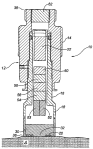
As shown schematically in Figure 4, the probe (10) has a resistance
measurement
module (52) for measuring the electrical resistance of the resistive element
(20). In
one embodiment the resistance measurement module (52) comprises a circuit
containing a meter for measuring the resistivity of the resistive element, and
a switch
means for governing the flow of electrical energy to the resistive element
(28).
The probe (10) also has a temperature sensing device (30). The temperature
sensing
device (30) may be a thermocouple, and is preferably disposed immediately
adjacent
to the unexposed surface of the CME (28). The temperature sensor (30) provides
a
temperature reading of the CME (28) at the time that its resistivity is
measured. The
temperature reading is required if compensation for thermal expansion (or lack
thereof) of the CME (28) is to be calculated as discussed above. The probe may
also
have a pressure sensor (32) that is exposed to the environment in a position
proximate to the CME (28). The pressure sensor (32) provides a pressure
reading of
the environment at the time that the resistivity is of the CME (28) is
measured. The
pressure level of the environment is a variable that can be accounted for in
the metal
loss calculations. As shown in Figure 4, the probe (10) has a temperature
measurement module (53) and a pressure measurement module (54) connected to
the
temperature sensing device (30) and the pressure sensor (32). This module is
capable of simultaneously reading the temperature of the CME (28) from the
temperature sensing device (30) and of reading the pressure of the environment
from
the pressure sensor (32) at the time that the resistivity of the CME (28) is
being
measured.
The probe has a memory module (58) for storing resistance, temperature and
pressure data. The memory may comprise solid state memory chips as are well
known in the art, connected to the measurement modules (52, 53, 54) for
recording
CA 02548301 2006-06-05
WO 2005/054821 PCT/CA2004/002077
5 and storing the resistivity, temperature and pressure readings until such
time as this
information is offloaded from the probe (10). The memory module (58) may also
be
configured such that the stored information for each reading also includes
information regarding the probe type, the CME type and a time stamp. The probe
(10) also has means for downloading information from the memory module (58) to
10 an external data storage and analysis system. As shown in Figure 4, the
means for
downloading information may be comprised of an external interface module (62).
In
one embodiment, the interface module (62) may be a hard wire connection, which
facilitates real time monitoring. In another embodiment, the interface (62)
may be
configured for the use of a wireless connection system facilitating the
transmission
of information to a handheld device if desired. The configuration of the
download
means will be largely governed by the location of the probe, and by the type
of
instrument that is being monitored.
The probe (10) has a control means for controlling the measurement modules and
the memory. The control means may comprise a controller module (56) as shown
in
Figure 4. The controller module (56) manages all of the data collection, data
transmission and power transmission using internal circuitry switching. The
controller module (56) activates the measurement circuits at preset time
intervals or
upon command.
It should be understood that for ease of explanation the various modules have
been
described as separate units, however the resistance measurement module (52),
the
temperature measurement module (53) and pressure measurement module (54), the
controller module (56), the memory module (58) and the external interface
module
(60) may comprise circuits contained on a single microchip that is connected
to the
power source (22), to the sensing devices and to the resistive element (28).
The
electronics in the probe (10) may be located immediately adjacent to the CME
(28)
fiu-ther reducing and eliminating any detrimental thermocouple effects.
In use, a baseline resistance measurement and temperature measurement is
talcen
immediately upon installation of the probe. This reading will be stored in
memory
CA 02548301 2006-06-05
WO 2005/054821 PCT/CA2004/002077
11
S and used as a reference point to compare subsequent readings to. The
resistance
measurements may be converted to a measurement of the thickness of the CME
(28), using the formulae detailed above. Temperature adjustments are only
necessary if the measurement temperature is different from the baseline
temperature
used to establish a baseline resistance reading. In Figure 6, the electrical
resistance
of a CME which was initially 0.05" (1.27mm) is shown. The increase in
resistance
is relatively linear until approximately 40% of the thickness of the CME is
lost, at
which point the resistance begins to increase exponentially. However, the
amount of
metal loss may be assumed to be linear between any two consecutive
measurements.
This assumption is based on the trapezoidal rule of mathematics which permits
the
1 S approximation of any curve by a series of trapezoids.
Pressure adjustments are only required when the operating pressure levels
equal or
exceed the levels required to physically deform the CME. When the pressure of
the
environment reaches levels such that the CME will physically deform, by either
plastic or elastic means, adjustments for pressure are necessary and are
undertaken
using conventional and accepted practices.
As depicted in Figure 1, in one embodiment of the probe (10), the first end of
the
hollow body (36) may be comprised of an element carrier (18) for securely
positioning the CME (28) such that one surface is exposed to the environment.
The
element carrier (18) releasably attaches to one end of a central probe body
(16). The
attachment means may be an adjustment nut, or such other suitable attachment
means as are commonly used in the art. The other end of the central probe body
(16) attaches to a carrier plug (14) that extends to the second end of the
probe (38).
The Garner plug (14) facilitates the sealed insertion of the probe (10) into
the pipe,
tubing or vessel that is being monitored, thereby preventing the escape of
corrosive
or. erosive substances from the environment. The hollow body (12) may be
constructed from any suitable corrosion resistant material. The contents of
the
hollow body (12) may be embedded in an insulating solid such as silicon, or
such
other suitable insulating material. This embodiment is well suited for the
monitoring of surface apparatus.
CA 02548301 2006-06-05
WO 2005/054821 PCT/CA2004/002077
12
As shown in Figure 4, in another embodiment, a monitoring assembly may be
designed to facilitate the use of the probe (10) in the downhole environment
in oil
and gas wells. The down hole assembly is comprised of a hollow carrier (60)
that is
sized to provide the same flow cross section as the production tubing while
the
outside diameter is sized to ensure clearance for the well casing. Both ends
of the
hollow Garner (60) may be threaded to facilitate insertion into the production
tubing.
The probe (10) is securely inserted into an opening (64) in the Garner walls
such that
one surface of the resistive element is exposed to the interior of the hollow
carrier
(60). The hollow carrier (60) has an electronics receptacle .(62) adjacent to
the
opening (60). An external connector (65) is mounted in the electronics
receptacle
(62) and is connected to the probe (10). The probe electronics in the probe
(10) and
the connections to the external connector may be encased in an epoxy and
secured to
the hollow carrier (60) with a carrier lock having a spring pin locking
mechanism
(not shown). The probe electronics may be connected to the surface of the well
by
means of a wire or cable that runs from the external connector (65) through a
wire
channel hollow carrier (66) and up the exterior surface of the production
tubing to
the surface.
As will be apparent to those slcilled in the art, various modifications,
adaptations and
variations of the foregoing specific disclosure can be made without departing
from
the scope of the invention claimed herein. The various features and elements
of the
described invention may be combined in a manner different from the
combinations
described or claimed herein, without departing from the scope of the
invention.