Note: Descriptions are shown in the official language in which they were submitted.
CA 02548398 2009-12-01
WO 2005/062105 PCT/US2003/039768
OPTICAL ARRANGEMENTS FOR HEAD MOUNTED DISPLAYS
TECHNICAL FIELD
[0002] The invention relates generally to visual displays and more
specifically
to optical arrangements for head mounted systems that use a single display.
1
CA 02548398 2009-12-01
WO 20051062105 PCT/US2003/039768
BACKGROUND OF THE INVENTION
[0003] Head Mounted Displays (HMDs) are a class of image display devices
that can be used to display images from television, digital versatile discs
(DVDs), computer
applications, game consoles, or other similar applications. A HMD can be
monocular ( a
single image viewed by one eye), biocular (a single image viewed by both
eyes), or
binocular (a different image viewed by each eye). Further, the image projected
to the eye(s)
may be viewed by the user as complete, or as superimposed on the user's view
of the
outside world. HMD designs must account for parameters such as image
resolution, the
distance of the virtual image from the eye, the size of the virtual image (or
the angle of the
virtual image), the distortions of the virtual image, the distance between the
left and the
right pupil of the user (inter pupillar distance (IPD)), diopter correction,
loss of light from
image splitting and transmission, power consumption, weight, and price.
Ideally, a single
HMD would account for these parameters over a variety of users and be able to
display an
image regardless of whether it was a stereo binocular image or a simple
monoscopic image.
[0004] If the resolution of a picture on the HMD's internal display is 800 x
600 pixels, an acceptable size for the virtual image produced by the HMD's
optics is a
virtual image diameter of approximately 1.5m (52"-56") at 2m distance which
corresponds
to approximately a 36 angle of view. To properly conform to the human head
and eyes,
the IPD should be variable between 45nun and 75mm. In order to compensate for
near- and
farsightedness, at least a 3 diopter correction is necessary.
[0005] The use of only one microdisplay in the HMD (instead of using one for
each eye) drastically reduces the price of the device. Typically, an
arrangement for such a
unit positions a microdisplay between the user's eyes. The image produced is
then split,
enlarged, and separately transmitted to each eye. There are numerous designs
known in the
art for beam splitting in single display HMDs with a center mounted display,
but none are
known that provide a solution that is cheap, light weight, small in size, and
capable of
displaying all varieties of images.
2
CA 02548398 2009-12-01
WO 2005/062105 PCT/US2003/039768
BRIEF SUMMARY OF THE INVENTION
[0006] Embodiments of the present invention reduce the splitting volume of
head mounted displays by focusing the image produced by a single display
screen and
splitting that image near its focal point. The separate sub-images are then
focused and
propagated through a plurality of optical sub-paths delivering the image to
separate
locations.
[0007] Some embodiments utilize an asymmetrical V-mirror splitter which can
consist of a partially reflective surface and a fully reflective surface
placed near the focal
point of the image. A portion of the light containing the image information is
then reflected
by the partially reflective surface and can be channeled to one eye, while the
remaining
portion of the light is reflected by the fully reflective surface and
channeled to the other eye.
[0008] Some embodiments may also utilize diffusers onto which real images
of the display are formed. Real images are projected onto diffusers by
transition optics
having a small numerical aperture, and transmitted to a viewer's eyes by
optics having a
larger numerical aperture.
[0009] Some embodiments may also utilize rotating reflectors. By reflecting
the split images off of multiple reflectors, the path of these images can be
altered in a
manner that allows the embodiments to adjust for the inter pupillar distances
of different
users. Other embodiments utilize the synchronized movement of multiple optical
blocks to
adjust for the interpupillary distance of different users.
[0010] Further embodiments may also utilize a light source to illuminate the
display. One possible arrangement may include individual sources of narrow
wavelength
light arranged to approximate a single wide band source.
[0011] The foregoing has outlined rather broadly the features and technical
advantages of the present invention in order that the detailed description of
the invention
that follows may be better understood. Additional features and advantages of
the invention
will be described hereinafter which form the subject of the claims of the
invention. It
should be appreciated that the conception and specific embodiment disclosed
may be
readily utilized as a basis for modifying or designing other structures for
carrying out the
3
CA 02548398 2009-12-01
WO 2005/062105 PCT/US2003/039768
same purposes of the present invention. It should also be realized that such
equivalent
constructions do not depart from the invention as set forth in the appended
claims. The
novel features which are believed to be characteristic of the invention, both
as to its
organization and method of operation, together with further objects and
advantages will be
better understood from the following description when considered in connection
with the
accompanying figures. It is to be expressly understood, however, that each of
the figures is
provided for the purpose of illustration and description only and is riot
intended as a
definition of the limits of the present invention.
4
CA 02548398 2009-12-01
WO 2005/062105 PCT/US2003/039768
BRIEF DESCRIPTION OF THE DRAWINGS
[0012] For a more complete understanding of the present invention, reference
is now made to the following descriptions taken in conjunction with the
accompanying
drawing, in which:
[0013] FIGURE 1 illustrates a top view of a head mounted display arranged
according to an embodiment of the present invention;
[0014] FIGURE 2 illustrates a prospective view of a head mounted display
arranged according to an embodiment of the present invention;
[0015] FIGURE 3 illustrates a prospective view of a head mounted display
arranged according to an embodiment the present invention;
[0016] FIGURES 4A and 4B illustrate a prospective view of a head mounted
display arranged according to an embodiment of the present invention;
[0017] FIGURES 5A and 5B illustrate a prospective view of ahead mounted
display arranged according to an embodiment of the present invention;
[0018] FIGURE 6 illustrates atop view of a portion of a head mounted display
arranged according to an embodiment of the present invention;
[0019] FIGURE 7 illustrates a top view of a portion of a head mounted display
arranged according to an embodiment of the present invention;
[0020] FIGURE 8 illustrates a top view of a portion of a head mounted display
arranged according to an embodiment of the present invention; and
[0021] FIGURE 9 illustrates a top view of a portion of a head mounted display
arranged according to an embodiment of the present invention.
CA 02548398 2009-12-01
WO 2005/062105 PCT/US2003/039768
DETAILED DESCRIPTION OF THE INVENTION
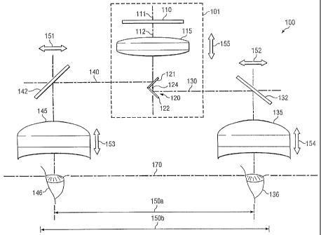
[0022] FIGURE 1 illustrates a top view of head mounted device 100 arranged
according to an embodiment of the present invention. Sub-image creation
section 101,
within device 100, creates a plurality of sub-images from a single image
source into a
plurality of optical sub-paths. Display 110 can be any suitable apparatus or
screen operable
to display a visual image of data, such as a liquid crystal display (LCD)
screen. Display 110
is situated along a display axis 111, which, in the embodiment shown, is
normal to the
screen of display 110 and perpendicular to facial plane 170 of a user. Display
110 is
designed to project a display image along optical path 112. In the arrangement
of section
101, optical path 112 lies along display axis 111. Display lens 115 is located
along, and
perpendicular to, optical path 112, and has display lens focal point 124.
Display lens focal
point 124 lies on optical path 112, and section 101 is arranged such that
display lens focal
point 124 lies within splitter 120. By focusing the display image before it is
split, the
splitting of volume of sub-image creation section 101 can be greatly reduced.
A small
splitting volume allows an embodiment to use small, light-weight splitting
elements and
allows HMD designs to include advantageous arrangements and additional optical
elements
that improve image quality and can increase the size of the image viewed by a
user. The
embodiment of FIGURE 1 is arranged to produce an image through (approximately)
collimated light emanated by (or being reflected from) display 110, thus
splitter 120 is
placed proximate to display lens focal point 124. The embodiments are not
limited to this
arrangement however, as splitter 120 should be arranged in the position most
appropriate to
the focused image. For example, if display 110 emits, transmits, or reflects
non collimated
light, the display image will be focused to a "point" that is not display lens
focal point 124,
and embodiments will arrange splitter 120 in a position proximate to this
focal area.
[0023] In embodiments using the arrangement of section 101, splitter 120 is an
asymmetric V-mirror splitter composed of a partially reflective surface 121
and a fully
reflective surface 122. The proximity of surfaces 121, 122 will be dependent
upon the size
of splitter 120 and the amount of splitter volume reduction section 101 is
arranged to
produce. Section 101 is further arranged so that surface 121 and surface 122
share a
common edge, and are arranged asymmetrically about display axis 111. Section
101 can
thus split a display image of display 110 into two separate display sub-
images. The term
6
CA 02548398 2009-12-01
WO 2005/062105 PCT/US2003/039768
sub-image is used to describe the multiple images of a display created by the
various
embodiments of the present invention. The sub-images of FIGURE 1 contain all
of the
information of a display, but embodiments may use sub-images that contain only
a portion
of an image.
[0024] Upon striking partially reflective surface 121, a portion of a display
image is reflected along left-eye optical sub-path 140, and becomes a left-eye
sub-image.
The portion of a display image not reflected by partially reflective surface
121 passes
through and strikes fully reflective surface 122, becoming a right-eye sub-
image, which is
reflected along right-eye optical sub-path 130. The result is an identical
left-eye sub-image
and right-eye sub-image traveling in opposite directions and containing
identical image
information.
[0025] Left-eye sub-image will follow optical sub-path 140 and be channeled
to left eye 146 of a user. Placed along optical sub-path 140 is left-eye
reflector 142, which
is a fully reflective surface arranged to redirect left-eye optical sub-path
140 by 90 and into
left eyepiece optics 145. The right-eye sub-image will follow optical sub-path
130 and be
channeled to right eye 136 of a user. Placed along optical sub-path 130 is
right-eye reflector
132, which is a fully reflective surface arranged to redirect right-eye
optical sub-path 130 by
90 and into right eyepiece optics 135. Right eyepiece optics 135 and left
eyepiece optics
145 can be a single lens or a combination of several lenses designed to
appropriately
magnify a right-eye sub-image for viewing by right eye 136 of the user and a
left-eye sub-
image for viewing by left eye 146 of the user, respectively.
[0026] Eyepiece optics 135 and 145 are adjustable single lenses, but other
embodiments may use multiple lenses or any other arrangement that
appropriately focuses a
right-eye sub-image and a left-eye sub-image for viewing by right eye 136 and
left eye 146,
respectively. Further, although reflectors 142, 132 of device 100 are depicted
as mirrors,
embodiments are not limited to the use of mirrors for redirecting an optical
sub-path.
Rather, prisms, partially reflective surfaces, polarizing beam splitters, or
any other suitable
arrangements can be used for redirecting an optical sub-path.
[0027] Device 100 is also capable of adjusting for the varying IPDs of
different users through the synchronized movements of optical elements. Right
eyepiece
7
CA 02548398 2009-12-01
WO 2005/062105 PCT/US2003/039768
optics 135 and left eyepiece optics 145 can shift through movements 152 and
151
respectively to create IPD 150a and IPD 150b, when section 101 shifts through
movement
155. When IPD distance 150a is changed to IPD 150b, section 101 is
simultaneously
shifted toward facial plane 170 in movement 155 (downwards in the view of
FIGURE 1).
When IPD 150b is changed to 150a, section 101 is simultaneously shifted away
from plane
170 (upwards in the view of FIGURE 1). These synchronized movements allow
device 100
to adjust to accommodate for the entire range between IPD 150a and 150b while
maintaining constant distances between surfaces 122, 121 and eyepiece optics
135, 145
along sub-paths 130 and 140, respectively. Device 100 is also capable of
diopter correction
through additional adjustments of movement 153 of left eyepiece optics 145 and
movement
154 of right eyepiece optics 135.
[0028] FIGURE 2 illustrates a prospective view of head mounted device 200
arranged according to an embodiment of the present invention. Head mounted
device 200
includes section 101, as described in relation to FIGURE 1, which operates to
split a display
image of display 110 into a left-eye sub-image traveling along left-eye
optical sub-path 140
and a right-eye sub-image traveling along right-eye optical sub-path 130. For
device 200,
left-eye transition optics 243 are placed along left-eye optical sub-path 140
to adjust the
left-eye sub-image for reflection by left-eye reflector 142 onto left-eye
diffuser 244. The
left-eye sub-image strikes the left-eye diffuser 244 and creates a real image
of the display on
the diffuser surface. The left eyepiece compound optics 245 then magnifies
this real image
appropriately for left eye 146.
[0029] The embodiment depicted in FIGURE 2 is described using diffusers
onto which real images are projected in order to prepare the image. Transition
optics,
having a small numerical aperture, project a real image onto the diffuser
surface, and
eyepiece optics having a large numerical aperture transport the image to the
eyes of a user.
Rather, any appropriate means may be used including microlens arrays,
diffraction gratings,
or other diffractive surfaces. For the purposes of the present invention, it
will be understood
that "diffuser" as used to describe the embodiments of the present invention,
refers to all
such means used to convert incident angular power density into an appropriate
exiting
angular power density.
8
CA 02548398 2009-12-01
WO 2005/062105 PCT/US2003/039768
[00301 In FIGURE 2, a right-eye sub-image follows the right-eye optical sub-
path 130 into right eye transition optics 233. The right eye transition optics
233 adjusts the
right-eye display sub-image appropriately for reflection by right-eye
reflector 132 onto
right-eye diffuser 234. The right-eye sub-image strikes right-eye diffuser 234
and creates a
real image. This real image is adjusted by right eyepiece compound optics 235
appropriately for right eye 136. Device 200 is capable of diopter correction
through
movement 253 of left-eye compound optics 245 and of movement 254 of right-eye
compound optics 235.
[00311 Device 200 is also capable of IPD adjustment through multiple
synchronous movements. IPD 150 can be shortened by shifting left-eye compound
optics
234 to the right with movement 251, and right-eye compound optics 235 to the
left with
movement 252. For the embodiment of FIGURE 2, segment 240 of optical sub-path
140
lies between transition optics 243 and diffuser 244, and segment 230 of
optical sub-path 130
lies between transition optics 233 and diffuser 234. Thus, as compound optics
235 and 245
are shifted in movement 252 and 251 to shorten distance 150, center section
201 should be
shifted away from the facial plane 170. The embodiment of FIGURE 2 describes
one
combination of synchronous movements that result in IPD adjustment, but
embodiments of
the present invention are not limited to the synchronous movements of FIGURE
2.
[00321 FIGURE 3 illustrates a prospective view of a head mounted device
arranged according to an embodiment of the present invention. Head mounted
device 300
includes section 101, as described in relation to FIGURE 1, to split a display
image of
display 110 into a left-eye sub-image traveling along left-eye optical sub-
path 140 and a
right-eye sub-image traveling along right-eye optical sub-path 130. In the
embodiment
depicted in FIGURE 3, a left-eye display sub-image follows left-eye optical
sub-path 140
and passes through a left-eye real image reflector 342 to strike left-eye
reflective diffuser
343, thus creating a real image. This real image is then reflected by left-eye
real image
reflector 342 into left eyepiece optics 145. Left eyepiece optics 145 adjusts
a reflected real
image appropriately for left-eye 146. A right-eye display sub-image will
follow right-eye
optical sub path 130 passing through right-eye real-image reflector 332 to
strike right-eye
reflective diffuser 333, thus creating a real image. This real image is
reflected by right-eye
9
CA 02548398 2009-12-01
WO 2005/062105 PCT/US2003/039768
real-image reflector 332 into right eyepiece optics 135 which will adjust a
reflected real-
image appropriately for right-eye 136.
[0033] The embodiment depicted in FIGURE 3 is described as using reflective
diffusers on which real images are formed. The present invention is not
limited to the use
of any one type of diffuser. Rather, the embodiments may use any appropriate
diffuser, as
previously described, and may be any appropriate shape such as spherical,
flat, or aspheric.
[0034] The embodiment in FIGURE 3 is also capable of diopter correction
through movement 153 of left eyepiece optics 145 and movement 154 of right
eyepiece
optics 135. Left-eye real-image reflector 342 and left eyepiece optics 145
collectively make
up left eyepiece 360. Right-eye real-image reflector 332 and right eyepiece
optics 135
collectively make up right eyepiece 361.
[0035] Device 300 is capable of IPD adjustment through multiple
simultaneous movements. The embodiment of FIGURE 3 simultaneously moves left
eyepiece 360 and right eyepiece 361 through movements 351 and 352 respectively
to set the
correct IPD. At the same time, movement 153 of left eyepiece optics 145 and
movement
154 of right eyepiece optics 135 are moved to maintain the optical path
lengths between
eyepiece optics 145, 135 and reflective diffusers 343, 333.
[0036] In device 300, left-eye real-image reflector 342 and right-eye real-
image reflector 332 are partially reflective surfaces, but embodiments are not
limited to the
arrangement depicted. Rather, embodiments may easily be adapted to any
arrangement,
such as those using prisms, or polarizing beam splitters, that appropriately
reflect light into
eyepiece optics 135 and 145 and transmit light from optical paths 130, 140
towards
reflective diffusers 333, 343, respectively.
[0037] FIGURES 4A and 4B illustrate a prospective view of head mounted
device 400 arranged according to an embodiment of the present invention. Head
mounted
device 400 uses right angle sub-image creation section 401 to create a
plurality of display
sub-images from a single image source. Similar to section 101 described in
FIGURES 1-3,
section 401 splits a display image of display 110 into left-eye sub-image
traveling along
left-eye optical sub-path 140 and a right-eye sub-image traveling along right-
eye optical
CA 02548398 2009-12-01
WO 2005/062105 PCT/US2003/039768
sub-path 130. In section 401, display 110 and display optics 115 are rotated
90 from
section 101 of FIGURES 1 through 3. Display 110 projects a display image along
optical
path 112 where it is focused by display optics 115. A display image then
strikes display
reflector 416, which redirects the optical path 112 by 90 . Reflector 416
causes a focused
display image to be directed into splitter 120. By redirecting the optical
path with reflector
416, the total volume of section 401 is reduced. The volume maybe further
reduced by
adding additional similar reflectors. In section 401, splitter 120 is arranged
such that
partially reflective surface 121 and fully reflective surface 122 are parallel
to display axis
111, and reflected focal point 424 of the display optics 115lies inside of
splitter 120.
Partially reflective surface 121 reflects a portion of a display image as a
left-eye display
sub-image to follow left-eye optical sub-path 140 such that it strikes left-
eye reflector 142.
The portion of the display image not reflected by partially reflective surface
121 is reflected
by fully reflective surface 122 as a right-eye sub-image along right-eye
optical sub-path 130
such that it strikes right-eye reflector 132.
[00381 Device 400 uses "real" images in a manner similar to device 200 of
FIGURE 2. For device 400, a left-eye display sub-image is reflected to left-
eye diffuser
243, where a real image is created. This real image is then transported to
left-eye 146 by
left eyepiece optics 145, which is designed to appropriately focus a left-eye
sub-image for
viewing by left-eye 146. A right-eye display sub-image will be reflected onto
right-eye
diffuser 234 creating a real image, which is transported to right-eye 136 by
right eyepiece
optics 135, which is designed to appropriately focus a right-eye sub-image for
viewing by
right-eye 136. Device 400 is capable of diopter correction through movement
153 of left
eyepiece optics 145 and movement 154 of right eyepiece optics 135.
[00391 FIGURE 4B illustrates the IPD correction capability of device 400. In
this embodiment, fully reflective surface 122 and partially reflective surface
121 are
rotatable about splitter axis 423 and with respect to each other. When fully
reflective
surface 122 is rotated clockwise about axis 423 and partially reflective
surface 121 is
rotated counter-clockwise, right-eye optical sub-path 130 and left-eye optical
sub-path 140
are deflected out of the plane, and are no longer 180 from each other. When
right-eye
optical sub-path 130 and left-eye optical sub-path 140 are deflected some
angles theta (0)
and theta prime (0'), the result is that device 400 has adjusted IPD 450.
Eyepieces 460 and
11
CA 02548398 2009-12-01
WO 2005/062105 PCT/US2003/039768
461 rotate inward simultaneously with the rotation of surfaces 121, 122.
Eyepiece 460
rotates counterclockwise to follow the downward deflection of sub-path 140,
and eyepiece
461 rotates clockwise to follow the downward deflection of sub-path 130. These
simultaneous rotations result in adjusted IPD 450.
[00401 FIGURES 5A and 5B illustrate a prospective view of a head mounted
display 500 arranged according to an embodiment of the present invention. For
head
mounted device 500, section 101 is again used to split the display image of
display 110 into
a left-eye sub-image traveling along left-eye optical sub-path 140 and a right-
eye sub-image
traveling along right-eye optical sub-path 130. For display 500, a left-eye
display sub-
image will strike a left-eye reflector 142 causing left-eye optical sub-path
140 to be
redirected 90 . A left-eye display sub-image will then strike second left-eye
reflector 543,
which also causes left-eye optical sub-path 140 to be redirected 90 . Left-eye
reflector 142
and second left-eye reflector 543 are arranged along a common left-eye
reflector axis 541.
Once a left-eye display sub-image has been reflected by the second left-eye
reflector 543, it
is reflected by third left left-eye reflector 544 and redirected onto left-eye
diffuser 243.
[00411 Similarly, a right-eye display sub-image will strike a right-eye
reflector
132 causing right-eye optical sub-path 130 to be redirected 90 . A right-eye
display sub-
image will then strike second right-eye reflector 533, which also causes right-
eye optical
sub-path 130 to be redirected 90 . Right-eye reflector 132 and second right-
eye reflectors
533 are arranged along a common right-eye reflector axis 531. Once a right-eye
display
sub-image has been reflected by second right-eye reflector 533, it is
reflected by third right-
eye reflector 534 and redirected onto right-eye diffuser 233.
[00421 A real-image created on left-eye diffuser 243 is transmitted to left-
eye
146 by left eyepiece optics 145. Left eyepiece 560 is made up of second left-
eye reflector
543, third left-eye reflector 544, left-eye diffuser 243, and left eyepiece
optics 145,
collectively. A real-image created on right-eye diffuser 233 is transmitted to
right-eye 136
by right eyepiece optics 135. Right eyepiece 561 is made up of second right-
eye reflector
533, third right-eye reflector 534, right-eye diffuser 233, and right eyepiece
optics 135,
collectively. Device 500 is capable of diopter correction through movement 153
of left
eyepiece optics 145 and movement 154 of right eyepiece optics 135.
12
CA 02548398 2009-12-01
WO 2005/062105 PCT/US2003/039768
[0043] Device 500 can adjust IPD 150 as depicted in FIGURE 5B. In Device
500, left eyepiece 560 is rotatable about axis 541 with respect to left-eye
reflector 142.
When left eyepiece 560 rotates counter-clockwise about left-eye reflector axis
541, optical
sub-path 140 is deflected from its previous path by some angle phi (cp).
Similarly, right
eyepiece 561 is rotatable about axis 531 with respect to right-eye reflector
132. When right
eyepiece 561 rotates clockwise about the right-eye reflector axis 531, optical
sub-path 130
is deflected some angle phi prime (cp') from its previous path. These
deflections result in
left eyepiece 560 and right eyepiece 561 rotating in the plane of the users
face to adjusted
IPD 550.
[0044] FIGURE 6 illustrates a top view of a portion of a head mounted device
arranged according to an embodiment of the present invention. FIGURES 1-5 have
depicted embodiments using sub-image creation sections 101 and 401. However,
embodiments are not limited to these arrangements. In FIGURE 6, sub-image
creation
section 600 includes display 110 arranged normal to display axis 111. Display
110 projects
a display image along optical path 112. A display image can then be focused by
display
lens 115 having a lens focal point 124. Splitter 620 is a symmetric V-mirror
splitter
composed of right fully reflective surface 622 and left fully reflective
surface 621 that share
a common edge and are arranged symmetrically about display axis 111. FIGURE 6
has
been depicted and described using fully reflective surfaces, but such
arrangements may be
readily adapted to the use of polarizing beam splitters or partially
reflective surfaces as well.
The arrangement of section 601 results in a display image projected by display
110 which is
focused by display lens 115 and split into two display sub-images, one
reflected along right-
eye optical sub-path 130 and one along left-eye optical sub-path 140.
[0045] Further optimization of the various embodiments of the present
invention can be made by the use of collimated (or approximately collimated)
light. A
display that (approximately) produces, reflects, or is illuminated by
collimated light can
improve image quality and simplifies device arrangement. There are numerous
methods of
producing and providing collimated light to different aspects of HMD's, and
embodiments
are not limited to any one.
13
CA 02548398 2009-12-01
WO 2005/062105 PCT/US2003/039768
[0046] FIGURE 7 illustrates a top view of a portion of a head mounted device
arranged according to the present invention. In sub-image creation section
700, display 110
is arranged nonnal to display axis 111. Display lens 115 is interposed between
display 110
and splitter 620. Splitter 620 is arranged as a symmetric V mirror splitter
with fully
reflective surface 621 and fully reflective surface 722. Focal point 124 of
lens 115 is
proximate to splitter 620. Display 110 is illuminated by light sources 708 and
709 which
are reflected by source reflector 707, which may be a polarization splitter,
or a partially
reflective mirror, or other appropriate reflector. Sources 708 and 709 are
arranged adjacent
to display axis 111 and in a plane with reflected focal point 124R. The sub-
image created
by source 708 and display 110 will be focused by lens 115 and incident upon
reflective
surface 722 of splitter 620. When display 110 is illuminated by source 709, a
separate
display sub-image is created and focused by lens 115. Because source 709 is
positioned
below reflected focal point 124R, the sub-image created by source 709 and
display 110 will
be focused by lens 115 and incident upon reflective surface 621 of splitter
620.
[0047] In the embodiment of FIGURE 7, two complete and independent
images (referred to again as sub-images) of display 110 are created, and each
sub-image is a
full image of display 110. In the embodiment of FIGURE 7, splitter 620 does
not split a
single image to create sub-images, but rather splits the angular space of the
display
reflection allowing the independently created images to be redirected along
separate paths.
[0048] FIGURE 8 illustrates a top view of a portion of a head mounted device
800 arranged according to an embodiment of the present invention using sub-
image creation
section 101. Blue source light 801 is arranged along the source light optical
path 806,
preferably in a position at or near reflective focal point 124R of display
optics 115. Blue
source light 801 may be any light source capable of producing blue light, such
as Nichia
NSCx100 series light emitting diode (LED). Light from blue source 801 passes
through a
first color filter 804 arranged at an appropriate angle to the optical path
and selected in order
to pass blue light and to reflect green light. Green source 802 is placed
adjacent to source
light optical path 806 and arranged in order to reflect light off of first
color filter 804 in a
way that simulates placing green source 802 in the same location as blue
source 801. Blue
light and the reflected green light follow source light optical path 806
passing through
second color filter 805 arranged at an appropriate angle to source light
optical path 806.
14
CA 02548398 2009-12-01
WO 2005/062105 PCT/US2003/039768
[0049] Second color filter 805 is selected such that it passes blue and green
light, but reflects red light. Red source 803 is placed adjacent to source
light optical path
806 and arranged in order to reflect light of second color filter 805 in a way
that simulates
placing red source 803 in the same location as blue source 801. Blue light,
reflected green
light, and reflected red light then follows source light optical path 806 and
is reflected by
source light reflector 807. In the depicted embodiment, source light reflector
807 can be a
polarizing reflector arranged about display axis 111 and along optical path
112. The
combined blue, green, and red light is polarized and reflected off of source
light reflector
807, through display optics 115. In the depicted embodiment, display optics
115 is a lens
selected to have a focal point of 124 (and a reflected focal point 124R). When
passed
through display optics 115, the combined blue, green, and red light is
collimated and
illuminates display 110. FIGURE 8 depicts the illumination of display 110 from
a single
direction, but the embodiments are not limited to a single direction. Rather,
the illumination
system of FIGURE 8 can be easily adapted for multiple direction illumination
as in
FIGURE 7.
[0050] The embodiments of the present invention are not limited to
arrangements that place an image splitter proximate to the focal point of a
focusing optic.
Rather, embodiments of the present invention are able to reduce the splitting
volume of
various applications, by positioning the image sputter to split a display
image focused in a
small area.
[0051] FIGURE 9 illustrates the reduced splitting volume created by
embodiments of the present invention. In FIGURE 9, display 110 is illuminated,
thus
creating a display image. The display image propogates along optical path 112
arranged
along display axis 111. Display lens 115, having a display lens focal point
124a, focuses
the display image in order to provide a reduced splitting volume. The point
where the
splitting volume is smallest will depend on the light illuminating the
display.
[0052] When display 110 is illuminated by source 908a positioned at reflective
display lens focal point 924a, display lens 115 will collimate the light
reflected from source
reflector 707. This results in a display image that is focused by display lens
115 to
approximately display lens focal point 124a. When display 110 is illuminated
by source
CA 02548398 2009-12-01
WO 2005/062105 PCT/US2003/039768
908b positioned at point 924b which is closer to display axis 111, the light
reflected from
source 707 will be divergent as it strikes display 110. Thus, the display
image will be
focused to approximately point 124c. When display 110 is illuminated by source
908c,
positioned at a point 924c which is farther away from display axis 111, the
light reflected
from source reflector 707 will be convergent as it strikes display 110. Thus,
the display
image will be focused to approximately point 124b. Embodiments of the present
invention
can thus be arranged to split the display image at whichever point is most
appropriate.
[00531 Although the present invention and its advantages have been described
in detail, it should be understood that various changes, substitutions and
alterations can be
made herein without departing from the invention as defined by the appended
claims.
Moreover, the scope of the present application is not intended to be limited
to the particular
embodiments of the process, machine, manufacture, composition of matter,
means, methods
and steps described in the specification. As one will readily appreciate from
the disclosure,
processes, machines, manufacture, compositions of matter, means, methods, or
steps,
presently existing or later to be developed that perform substantially the
same function or
achieve substantially the same result as the corresponding embodiments
described herein
may be utilized. Accordingly, the appended claims are intended to include
within their
scope such processes, machines, manufacture, compositions of matter, means,
methods, or
steps.
16