Note: Descriptions are shown in the official language in which they were submitted.
CA 02548617 2011-10-12
RETRACTABLE SHADE FOR COVERINGS FOR ARCHITECTURAL
OPENINGS
BACKGROUND OF THE INVENTION
Field of the Invention:
The present invention relates generally to retractable coverings for
architectural openings and fabrics for use therein wherein the fabric includes
a
flexible support structure and a plurality of vanes or slats mounted on the
support structure with the movement of the vanes or slats being dependent
upon the movement of the support structure.
Description of the Relevant Art
Retractable coverings for architectural openings have assumed
numerous forms over a long period of time. Originally, coverings for
architectural openings such as windows, doors, archways or the like consisted
principally of fabric draped across the architectural openings. Such early
forms of coverings evolved into retractable roller shades, curtains,
draperies,
and the like wherein the covering could be extended across the architectural
opening or retracted to a top or side of the opening.
An early but still popular form of covering for architectural openings is
the Venetian blind wherein a plurality of vertically extending cord ladders
support parallel horizontally extending slats in a manner such that the slats
can be pivoted about their longitudinal axes between open and closed
positions and the entire blind can be moved between an extended position
wherein it extends across the architectural opening and a retracted position
1
CA 02548617 2006-06-07
WO 2005/062875
PCT/US2004/043043
where the slats are accumulated in a vertical stack adjacent to the top of the
architectural opening.
Vertical blinds are also available which are very similar to Venetian
blinds except the slats or vanes extend vertically and are suspended from
their upper ends for pivotal movement about their longitudinal vertical axes.
The entire blind can be extended across the opening or retracted adjacent to
one or more sides of the opening in a horizontal stack.
More recently, cellular shades have become popular not only because
they are aesthetically attractive but also because they provide improved
insulation across architectural openings where typically heat can otherwise be
lost. Cellular shades have assumed numerous forms including a plurality of
longitudinally extending tubes made of a flexible or semi-rigid material which
can be transversely collapsed. The cellular shade can thereby be extended
across an architectural opening or retracted adjacent the top or bottom edge
of the opening with the cells transversely collapsed in a vertical stack.
A more recent form of cellular shade includes a pair of spaced flexible
sheets, which are typically sheer fabric, with the sheets being interconnected
by vertically spaced horizontally extending vanes which may be rigid or
flexible. The vanes are movable between open and closed positions by -
shifting the sheets of material in opposite vertical directions. The entire
covering can be extended across the opening or retracted along one edge of
the opening typically by rolling the fabric material comprised of the sheets
of
material and interconnecting vanes about a roller.
The recent emphasis on design in homes and building structures has
maintained pressure on the industry to create unique aesthetically attractive
coverings for architectural openings which also have utilitarian functions
such
as insulating the opening to minimize the loss of heat therethrough.
It is to respond to the demand of the market that the present invention
has been made.
2
CA 02548617 2006-06-07
WO 2005/062875
PCT/US2004/043043
BRIEF SUMMARY OF THE INVENTION
The covering of the present invention includes a fabric material that
can be extended across an architectural opening or retracted adjacent an
edge of the opening and a control system for manipulating the fabric material.
The fabric material can assume various forms but wherein generally a support
structure supports a plurality of slats or vanes in a manner such that the
movement of the vanes is dependent upon movement of the support
structure. The support structure could be in the form of a sheet of flexible
material, strips of flexible ribbon, tape, or the like, flexible elongated
strands or
elements which could be monofilaments, cord or string made of natural or
synthetic fibers, transversely collapsible cellular structures, or the like.
The
support structure while typically being vertically oriented can also be
horizontally disposed so the covering can be used in a skylight as well as on
windows, doors, archways, or the like.
The slats or vanes, which are supported on the support structure, can
assume numerous forms including rigid, semi-rigid or flexible strips of
material
of various configurations and relationships connected to the support structure
at spaced locations to define cellular vanes between connection locations.
The vanes formed from the strips of material are connected to the support
structure in a manner such that they can be gathered into a compact stack
adjacent one edge of an architectural opening when the fabric is mounted on
a control system for extending or retracting the fabric structure across the
architectural opening. The control system for such a covering in the preferred
embodiment is a lift mechanism which lifts or gathers the support structure
and consequently the vanes that follow into a stack adjacent to an edge of the
architectural opening.
As will be appreciated with the detailed description that follows, the
vanes can be interconnected with each other, connected individually to the
support structure or they can be mounted on the support structure so that
each vane is not directly secured to the support structure but rather the
support structure is used to engage and lift the lowermost vanes in the fabric
3
CA 02548617 2006-06-07
WO 2005/062875
PCT/US2004/043043
when the covering is being retracted thereby causing the remaining vanes to
accumulate and stack on the lowermost vanes.
Other aspects, features and details of the present invention can be
more completely understood by reference to the following detailed description
of preferred embodiments, taken in conjunction with the drawings and from
the appended claims.
BRIEF DESCRIPTION OF THE DRAWINGS
Fig. 1 is a fragmentary isometric illustrating a first embodiment of a
covering in a fully extended position in accordance with the present
invention.
Fig. 2 is a side elevation of the covering as shown in Fig. I.
Fig. 3A is a side elevation similar to Fig. 2 with the ,covering partially
retracted.
Fig. 3B is an enlarged fragmentary side elevation of the covering of
Fig. 1 in a partially retracted position.
Fig. 3C is a partially exploded side elevation similar to Fig. 3B.
Fig. 4 is a side elevation of the covering of Fig. 1 in a fully retracted
position.
Fig. 5 is an exploded side elevation of a plurality of vanes used in a
second embodiment of the covering of the present invention illustrating the
manner in which the vanes are interconnected.
Fig. 6A is an enlarged side elevation of a vane used in the covering of
Fig. 5.
Fig. 6B is a further enlarged fragmentary side elevation of an upper
segment of the vane as shown in Fig. 6A.
Fig. 6C is a fragmentary elevation similar to Fig. 6B showing the upper
segment before folding.
Fig. 7 is an isometric of a third embodiment of a fabric for use in a
covering in accordance with the present invention and with the fabric in a
fully
extended ,position.
Fig. 7A is a side elevation of the fabric as shown in Fig. 7.
4
CA 02548617 2006-06-07
WO 2005/062875
PCT/US2004/043043
Fig. 76 is an isometric of the fabric of Fig. 7 shown in a partially
retracted position.
Fig. 7C is a side elevation of the fabric as shown in Fig. 76 with a lift
mechanism shown in dashed lines.
Fig. 7D is an isometric of the fabric of Fig. 7 in a fully retracted position.
Fig. 7E is a side elevation of the fabric as shown in Fig. 70 with a lift
mechanism shown in dashed lines.
Fig. 7F is an enlarged fragmentary elevation of an uppermost cell in the
support structure of the fabric of Fig. 7 connected to the next lower cell and
with a slat connected to the uppermost cell.
Fig. 8A is an isometric of a fabric similar to that of Fig. ,7 in a fully
extended position but wherein the slats are flat in cross section rather than
arcuate.
Fig. 86 is a side elevation of the fabric of Fig. 8A.
Fig. 9A is an isometric view of a fourth embodiment of a fabric in
accordance with the present invention shown in a fully extended position.
Fig. 9B is a side elevation of the fabric as shown in Fig. 9A.
Fig. 90 is an enlarged side elevation of the fabric of Fig. 9A in a fully
retracted position and showing a lift system in dashed lines.
Fig. 9D is a further enlarged fragmentary side elevation of the fabric of
Fig. 9A showing the uppermost cell of the support structure connected to the
next lower cell and with the slats connected to opposite sides of the
uppermost cell.
Fig. 10A is an isometric of a fifth embodiment of a fabric in accordance
with the present invention shown in a fully extended position.
Fig. 106 is a side elevation of the fabric as shown in Fig. 10A.
Fig. 10C is an isometric of a variation of the fabric of Fig. 10A in a fully
extended position with slats on only one side of the cellular support
structure.
Fig. 10D is a side elevation of the fabric shown in Fig. 100.
Fig. 11A is an isometric of a fully extended variation of the embodiment
of Figs. 9A and 96 with slats on only one side of the cellular support
structure.
5
CA 02548617 2006-06-07
WO 2005/062875
PCT/US2004/043043
Fig. 11B is a side elevation of the fabric as shown in Fig. 11A.
Fig. 11C is an isometric of the fabric of Fig. 11A in a partially retracted
position.
Fig. 11D is a side elevation of the fabric of Fig. 11A in a partially
retracted position.
Fig. 12A is an isometric of a sixth embodiment of a fabric in
accordance with the present invention shown in a fully extended position.
Fig. 12B is a side elevation of the fabric as shown in Fig. 12A.
Fig. 13A is an isometric of a seventh embodiment of a fabric in
accordance with the present invention in a fully extended position.
Fig. 13B is a side elevation of the fabric of Fig. 13A.
Fig. 14A is an isometric of an eighth embodiment of a fabric in
accordance with the present invention in a partially extended position.
Fig. 14B is a side elevation of the fabric as shown in Fig. 14A.
Fig. 140 is a side elevation of the fabric shown in Fig. 14A in a fully
retracted position.
Fig. 140 is a side elevation of the fabric of Fig. 14A in a fully extended
position.
Fig. 15A is a side elevation of a variation of the fabric of Fig. 14A with
slats on both sides of the pleated support structure and with the fabric fully
extended.
Fig. 15B is an isometric of the fabric as shown in Fig. 15A in a partially
retracted position.
Fig. 150 is an isometric of the fabric shown in Fig. 15A in a fully
extended position.
Fig. 15D is an isometric of the fabric of Fig. 15A.
Fig. 16A is a side elevation of a ninth embodiment of a fabric in
accordance with the present invention shown in a fully extended position.
Fig. 16B is an enlarged side elevation of the fabric shown in the circled
area of Fig. 16A.
6
CA 02548617 2006-06-07
WO 2005/062875
PCT/US2004/043043
Fig. 16C is a side elevation of the fabric shown in Fig. 16A in a partially
retracted position.
Fig. 17A is a fragmentary isometric showing a tenth embodiment of a
fabric in accordance with the present invention mounted horizontally and in a
fully extended position.
Fig. 17B is a fragmentary vertical section of the fabric of Fig. 27A in a
fully retracted position.
Fig. 170 is a fragmentary vertical section of the fabric of Fig. 27A in a
fully extended position.
Fig. 18A is a fragmentary side elevation of an eleventh embodiment of
a fabric in accordance with the present invention in a fully extended
position.
Fig. 18B is an enlarged side elevation showing the encircled area of
Fig. 18A.
Fig. 180 is a side elevation of the fabric of Fig. 18A in a fully retracted
position.
Fig. 18D is a side elevation of the fabric of Fig. 18A in a partially
retracted position.
Fig. 19A is an isometric of a twelfth embodiment of a fabric in
accordance with the present invention shown in a fully extended position.
Fig. 19B is a side elevation of the fabric as shown in Fig. 19A.
Fig. 190 is an isometric of the fabric of Fig. 19A in a partially retracted
position.
Fig. 19D is an enlarged side elevation of the fabric of Fig. 19A in a fully
retracted position.
Fig. 20A is an isometric of a thirteenth embodiment of a fabric in
accordance with the present invention shown in a fully extended position.
Fig. 20B is a side elevation of the fabric as shown in Fig. 20A.
Fig. 200 is an isometric of the fabric of Fig. 20A in a partially retracted
position.
Fig. 20D is a side elevation of the fabric of Fig. 20A in a fully retracted
position.
7
CA 02548617 2006-06-07
WO 2005/062875
PCT/US2004/043043
Fig. 21A is an isometric of a fourteenth embodiment of a fabric in
accordance with the present invention in a fully extended position.
Fig. 21B is a side elevation of the fabric shown in Fig. 21A.
Fig. 210 is an isometric of the fabric shown in Fig. 21A in a partially
retracted position.
Fig. 21D is a side elevation of the fabric of Fig. 21A in a fully retracted
position.
Fig. 22A is a side elevation of a fifteenth embodiment of a fabric in
accordance with the present invention in a fully extended position.
Fig. 22B is an isometric of the fabric as shown in Fig. 22A.
Fig. 220 is a side elevation of the fabric shown in Fig. 22A in a fully
retracted position.
Fig. 22D is an enlarged fragmentary side elevation showing the
formation of a cell in the support structure and a vane from a common strip of
material.
Fig. 23A is an isometric of a sixteenth embodiment of a fabric in
accordance with the present invention shown in a fully extended position.
Fig. 23B is a side elevation of the fabric as shown in Fig. 23A.
Fig. 230 is an isometric of a variation of the fabric shown in Fig. 23A in
a fully extended position.
Fig. 23D is an enlarged fragmentary side elevation of the lowermost
cell and slat of the fabric of Fig. 23A.
Fig. 24A is an isometric of a cellular support structure used in a
seventeenth embodiment of a fabric in accordance with the present invention.
Fig. 24B is an isometric of a variation of the support structure of Fig.
24A.
Fig. 240 is an isometric of an interconnected vane panel for use with
the support structure of Fig. 24A or 24B.
Fig. 24D is an isometric showing the panel of Fig. 240 mounted on the
cellular support structure of Fig. 24E.
Fig. 24E is a side elevation of the support structure of Fig. 24A.
8
CA 02548617 2006-06-07
WO 2005/062875
PCT/US2004/043043
Fig. 25A is an isometric of an eighteenth embodiment of a fabric in
accordance with the present invention looking at the rear side of the fabric
with the fabric fully extended.
Fig. 25B is an enlarged isometric looking at the front side of the fabric
of Fig. 25A.
Fig. 250 is an end elevation of an open cell used in the support
structure of the fabric of Fig. 25A.
Fig. 26A is a side elevation of a nineteenth embodiment of a fabric in
accordance with the present invention shown in a fully extended position.
Fig. 26B is an isometric of the fabric as shown in Fig. 26A.
Fig. 26C is a side elevation of a strip of material from which a slat used
in the fabric of Fig. 26A is formed.
Fig. 26D is an enlarged side elevation similar to Fig. 260 with the slat
having been fully formed.
Fig. 26E is a side elevation of a different arrangement of the
embodiment of Fig. 22A wherein the slats used in the arrangement do not
have downturned flaps.
Fig. 26F is an enlarged elevation showing the encircled area of Fig.
26E.
Fig. 26G is a side elevation of a still further arrangement similar to Fig.
26E wherein the slats are mounted to assume a flatter arcuate configuration.
Fig. 26H is an enlarged elevation showing the encircled area of Fig.
26G.
Fig. 26J is a side elevation of a still further arrangement of the fabric
that is similar to that of Fig. 26G wherein there are slats on opposite sides
of
the support structure and an arcuate slat appearing weighted bottom rail.
Fig. 26K is a side elevation of a covering incorporating the fabric of Fig.
26J with the covering in a fully extended position.
Fig. 26L is a side elevation similar to Fig. 26K with the covering in a
fully retracted position.
9
CA 02548617 2006-06-07
WO 2005/062875
PCT/US2004/043043
Fig. 27A is a side elevation of a twentieth embodiment of a fabric in
accordance with the present invention.
Fig. 27B is an isometric of the fabric as shown in Fig. 27A.
Fig. 27K is an isometric of another embodiment of a fabric in
accordance with the present invention which is similar to the arrangement of
Fig. 27A except the support structure is in the form of a plurality of tapes
or
ribbons.
Fig. 27L is another arrangement of a fabric in accordance with the
present invention which is similar to the embodiment of Fig. 27K except the
support structure is in the form of a plurality of flexible monofilaments or
the
like.
Fig. 27M is an enlarged fragmentary section taken along line 27M-27M
of Fig. 27L.
Fig. 27N is an isometric of another arrangement of a fabric in
accordance with the present invention.
Fig. 27P is a side elevation of the fabric of Fig. 27N.
Fig. 27S is an enlarged fragmentary section taken along line 27S-27S
of Fig. 27N.
Fig. 27T is a section taken along line 27T-27T of Fig. 27S.
Fig. 27U is an isometric of a cord ladder used in the fabric of Fig. 27N.
Fig. 28A is a side elevation of a twenty-first embodiment of a fabric in
accordance with the present invention connected to a roller and with the
fabric
fully extended.
Fig. 28B is a side elevation similar to Fig. 28A with the fabric partially
retracted onto the roller.
Fig. 29A is a fragmentary side elevation of a twenty-second
embodiment of a fabric in accordance with the present invention mounted on
a roll bar and with the fabric fully extended.
Fig. 29B is a side elevation similar to Fig. 29A with the fabric partially
retracted onto the roller.
CA 02548617 2006-06-07
WO 2005/062875
PCT/US2004/043043
Fig. 30A is a side elevation of a twenty-third embodiment of a fabric in
accordance with the present invention mounted on a roller and with the fabric
fully extended.
Fig. 30B is a side elevation similar to Fig. 30A with the fabric partially
retracted onto the roller.
Fig. 31A is a side elevation of a twenty-fourth embodiment of a fabric in
accordance with the present invention shown in a fully extended position and
supported by a roller.
Fig. 32A is a fragmentary isometric of a twenty-fifth embodiment of a
fabric in accordance with the present invention looking at the front of the
fabric.
Fig. 32B is an isometric of the fabric of Fig. 32A looking at the rear of
the fabric.
Fig. 32C is a side elevation of the fabric of Fig. 32A in a substantially
retracted position.
Fig. 32D is a side elevation of the fabric of Fig. 32A in a partially
retracted position.
Fig. 32E is a side elevation of the fabric of Fig. 32A in a fully extended
position.
Fig. 33A is a side elevation of a twenty-sixth embodiment of a fabric in
accordance with the present invention wherein the fabric is fully extended.
Fig. 33B is a side elevation of the fabric shown in Fig. 33A in a fully
retracted position.
Fig. 33C is a side elevation of a slat used in the fabric of Fig. 33A.
Fig. 34A is a side elevation of a twenty-seventh embodiment of a fabric
in accordance with the present invention in a fully extended position.
Fig. 34B is an enlarged side elevation of the fabric of Fig. 34A in a fully
retracted position.
Fig. 34C is a side elevation of a slat used in the fabric of Fig. 34A.
Fig. 35A is a side elevation of a twenty-eighth embodiment of a fabric
in accordance with the present invention shown in a fully extended position.
11
CA 02548617 2006-06-07
WO 2005/062875
PCT/US2004/043043
Fig. 35B is an enlarged side elevation of the fabric of Fig. 35A in a fully
retracted position.
Fig. 350 is a side elevation of a slat used in the fabric of Fig. 35A.
Fig. 36A is a side elevation of a shade incorporating a hybrid fabric
having an upper component with a plurality of arcuate slats suspended off
front and rear sides of a support structure and an integrated lower component
of a sheet of fabric connected to a roller along its bottom edge.
Fig. 36B is a fragmentary isometric of the shade shown in Fig. 36A.
Fig. 37A is a side elevation of a hybrid shade having an upper fabric
component of a plurality of interconnected hexagonal cells and a lower
component of a plurality of arcuate slats suspended from a support system.
Fig. 37B is a fragmentary isometric of the shade shown in Fig. 37A.
Fig. 38A is a front elevation of a shade having a control system for
moving both a top rail and a bottom rail having a fabric extending
therebetween and wherein the bottom rail is in a fully extended and lowered
position and the top rail is partially lowered.
Fig. 38B is a front elevation similar to Fig. 38A wherein the top and
bottom rails are both positioned at an intermediate location between the top
and bottom of an architectural opening in which the shade is disposed. ,
Fig. 39A is a front elevation of a shade used in an architectural opening
having a semi-circular top edge and wherein the top edge of the fabric in the
shade is movable vertically between a raised fully extended position and a
lowered fully retracted position wherein slats in the fabric of the shade are
accumulated adjacent to a bottom edge of the architectural opening.
Fig. 39B is a front elevation of the shade of Fig. 39A with the top edge
of the shade partially lowered.
Fig. 390 is a front elevation similar to Fig. 39B with the shade almost
entirely retracted.
Fig. 40 is an enlarged section taken along line 40-40 of Fig. 39B.
Fig. 41 is an enlarged fragmentary side elevation of the lower end of
the shade shown in Fig. 40.
12
CA 02548617 2006-06-07
WO 2005/062875
PCT/US2004/043043
Fig. 42 is a fragmentary side elevation similar to Fig. 41 wherein the
shade utilizes a bottom accumulating rail of a different configuration than
that
used in the embodiment of Fig. 41.
Fig. 43 is a side elevation of the accumulating rail shown in Fig. 42.
Fig. 44 is a fragmentary isometric of a material used to form the
accumulating rail of Figs. 42 and 43.
Fig. 45 is a front elevation of a shade in accordance with the present
invention utilizing a plurality of vertically adjacent shades for use in a
single
architectural opening and wherein each of the shades are fully extended.
Fig. 46 is a front elevation similar to Fig. 45 with each shade partially
retracted.
Fig. 47 is a front elevation similar to Fig. 46 with the shades fully
retracted.
Fig. 48A is a front elevation of a fully-extended shade in accordance
with the present invention utilizing a plurality of horizontally disposed
interconnected slats supported on a support structure wherein the fabric is of
a triangular configuration having its base horizontally disposed at the bottom
of the fabric.
Fig. 48B is a front elevation similar to Fig. 48A with the shade partially
retracted.
Fig. 49A is a front elevation of a shade in accordance with the present
invention having a circular shape wherein horizontally disposed slats are
supported on support structures adapted to move the slats from a fully
extended position to a retracted position on a horizontal diametric rail at
the
center of the circular fabric.
Fig. 49B is a front elevation similar to Fig. 49A with the shade partially
retracted.
Fig. 50A is a front elevation of a shade formed of a right triangular
configuration again with a plurality of horizontally disposed slats on a
support
structure wherein the top edge of the fabric is adapted to be lowered toward
the bottom edge when retracting the fabric.
13
CA 02548617 2006-06-07
WO 2005/062875
PCT/US2004/043043
Fig. 50B is a front elevation similar to Fig. 50A with the shade partially
retracted.
Fig. 51A is a front elevation of three adjacent side-by-side architectural
openings having a shade in accordance with the present invention
incorporated into each opening and wherein the lower edge of the fabric in the
shade is contoured so as to complement the lower edge of the fabric in
adjacent openings and wherein the shade in each opening is nearly fully
extended.
Fig. 51B is a front elevation of the architectural openings and shades
shown in Fig. 51A with the shades substantially fully retracted.
Fig. 52 is an isometric of a shade incorporating a further embodiment
having manually operated lift rails.
Fig. 52A is an enlarged section taken along line 52A-52A of Fig. 52.
Fig. 52B is an enlarged fragmentary section taken along line 52B-52B
of Fig. 52.
Fig. 52C is a section taken along line 520-520 of Fig. 52B.
Fig. 52D is a section taken along line 52D-52D of Fig. 52A.
Fig. 52E is a section taken along line 52E-52E of Fig. 52.
Fig. 52F is a section similar to Fig. 52 showing the clamp fingers in an
unlocking position.
Fig. 52G is an enlarged section taken along line 52G-52G of Fig. 52E.
Fig. 52H is an enlarged section taken along line 52H-52H of Fig. 52E.
Fig. 52J is an isometric looking at the top of a locking finger.
Fig. 52K is an isometric looking at the bottom of the locking finger of
Fig. 52J.
Fig. 52L is an enlarged section taken along line 52L-52L of Fig. 52D.
Fig. 53 is an isometric of the shade of Fig. 52 showing the midrail at an
elevated position.
Fig. 54 is a section similar to Fig. 53 with the midrail at an intermediate
location and with the fabric removed to show the operating system.
14
CA 02548617 2006-06-07
WO 2005/062875
PCT/US2004/043043
Fig. 55 is an isometric similar to Fig. 54 with the rails removed so as to
show more clearly the guide cords for guiding movement of the midrail.
Fig. 56 is an exploded fragmentary isometric showing the
interconnection of the top rail with the mounting bracket and the fabric.
Fig. 57 is a fragmentary isometric showing one end of the bottom rail
and its connection to a mounting bracket.
Fig. 58 is a isometric of the interconnection of the bottom rail with a
mounting bracket.
Fig. 59 is an isometric similar to Fig. 52 except where the covering is a
top down covering as opposed to a bottom up covering as shown in Fig. 52
and with the midrail in an elevated extended position.
Fig. 60 is an isometric similar to Fig. 59 with the midrail in a lowered
extended position.
Fig. 61 is an isometric of the shade of Fig. 59 with the fabric removed
to show the control system.
Fig. 62 is an isometric similar to Fig. 51 with the rails also removed so
as to show the guide cord system.
Fig. 63 is an isometric of a shade similar to Fig. 52 wherein there are
upper and lower midrails for a top down/bottom up covering and wherein the
covering is in a fully extended position.
Fig. 64 is an isometric of the covering of Fig. 63 with the upper midrail
having been dropped and the lower midrail raised into intermediate positions.
Fig. 65 is an isometric similar to Fig. 64 with the fabric material
removed.
Fig. 66 is an isometric similar to Fig. 65 with the rails removed so as to
show the guide cords.
Fig. 67 is an isometric of a further embodiment of the covering of Fig.
52 wherein the covering is a top down covering and the bottom rail supports a
dummy vane.
Fig. 68 is an isometric similar to Fig. 67 with the fabric having been
removed.
CA 02548617 2006-06-07
WO 2005/062875
PCT/US2004/043043
Fig. 69 is an isometric similar to Fig. 68 with the rails having also been
removed.
Fig. 70 is an isometric of a further embodiment consistent with the
present invention wherein guide cords are suspended in an architectural
opening and a fabric is mounted on the guide cords having a weighted bottom
vane and a movable top rail.
Fig. 71 is an enlarged section taken along line 71-71 of Fig. 70.
Fig. 72 is a section taken along line 72-72 of Fig. 71.
Fig. 73A is an exploded isometric showing the weighted bottom vane
for the covering shown in Fig. 70.
Fig. 73B is an exploded isometric showing the opposite end of the vane
from that shown in Fig. 73A.
Fig. 74 is a fragmentary isometric of a top-down version of a further
embodiment similar to that illustrated in Figs. 52-73B.
Fig. 75 is a fragmentary isometric similar to Fig. 74 with the handle for
moving the shade shown exploded.
Fig. 76 is a fragmentary vertical section taken through the shade as
shown in Fig. 74.
Fig. 77 is a vertical section with parts removed taken through the shade
of Fig. 74.
Fig. 78 is an enlarged fragmentary vertical section taken through the
top rail of the shade of Fig. 74.
Fig. 79 is an enlarged fragmentary vertical section taken through the
midrail of the shade of Fig. 74.
Fig. 80 is a fragmentary vertical section through the bottom rail of the
shade of Fig. 74.
Fig. 81 is a side elevation of a bottom-up version of the shade of Fig.
74.
Fig. 82 is a vertical section with parts removed similar to Fig. 81.
Fig. 83 is an enlarged fragmentary vertical section taken through the
top rail of the shade of Fig. 81.
16
CA 02548617 2006-06-07
WO 2005/062875
PCT/US2004/043043
Fig. 84 is an enlarged fragmentary vertical section taken through the
midrail of the shade of Fig. 81.
Fig. 85 is a fragmentary vertical section through the bottom rail of the
shade of Fig. 81.
Fig. 86 is an isometric looking at the outer end of an insert used in the
shade of Fig. 74.
Fig. 87 is an isometric looking at the inner end of the insert shown in
Fig. 86.
Fig. 88 is a top plan view of the insert as shown in Fig. 86.
Fig. 89 is an inner end elevation of the insert as shown in Fig. 87.
Fig. 90 is an outer end elevation of the insert as shown in Fig. 86.
Fig. 91 is a side elevation of the insert as shown in Fig. 86.
Fig. 92 is an isometric of the handle used in the top-down version of
the shade of Fig. 74.
Fig. 93 is an isometric of the handle used in the bottom-up version of
the shade of Figs. 81, 82, and 85.
Fig. 94 is an isometric of a protective strip used in the shade of Fig. 74
and as shown in section in Fig. 76.
Fig. 95 is an isometric of the extrusion used for the rails in the shade of
Fig. 74.
DETAILED DESCRIPTION OF THE INVENTION
The cellular shade of the present invention includes a control system
and a fabric supported on and manipulated by the control system. The fabric
is disclosed in different embodiments wherein it includes a support structure
on which a plurality of slats or vanes are supported in a manner such that the
movement of the slats or vanes is responsive to retraction or extension of the
support structure on which they are mounted and operatively associated. As
will be appreciated from the detailed descriptions that follow, the slats or
vanes can be in the form of flexible, rigid, or semi-rigid strips of material
connected to the support structure at spaced locations. The slats or vanes
17
CA 02548617 2006-06-07
WO 2005/062875
PCT/US2004/043043
are operatively connected to the support structure to move in response to
movement of the support structure. As used in this Specification, the term
"flexible" refers to materials that are capable of being flexed with examples
of
such materials being sheets of vinyl, woven or non-woven fabric, cords of
natural or synthetic fibers, monofilaments, and the like. The term "semi-
rigid"
refers to materials that are somewhat stiff but can be flexed or folded.
Examples of such materials would be resin reinforced fabric, polyvinyl
chloride, and the like. The term rigid refers to stiff materials which could
be
resin reinforced fabrics (to a greater degree than the "semi-rigid" fabrics),
polyethylene, wood, aluminum or other metals, and the like.
With reference first to Figs. 1-4, a first embodiment 30 of the shade or
covering of the present invention can be seen to include a headrail 32 having
an arcuate rigid valence 34 supported thereon and a fabric 36 that includes a
support structure in the form of a plurality of suspended flexible cords or
elements 38 that carry a weighted bottom rail or ballast bar 40 at their lower
ends and a plurality of interconnected slats 42 suspended from the headrail
and in operative engagement with the support structure.
As best seen in Figs. 2 and 4, the headrail 32, which is adapted to be
mounted to a frame (not shown) of an architectural opening in any
conventional manner includes an extruded element 44 that is interlocked with
a base member 46 with the extruded element including channels, beads, and
other formations for various purposes. The extruded element has one
channel 48 formed therein to receive an outer free edge 50 of the base
member 46 and a ridge 52 that is received in a channel 54 formed in the base
member so the extruded element is suspended from the base member but
can be slid longitudinally of the base member to mount on or remove the
extruded element from the base rnember. The extruded element further has a
rounded elongated bead 56 along its forwardmost free edge adapted to be
received in a channel 58 formed along the inside upper edge of the valence
34 so the valence, which is arcuate in transverse cross-section, can depend
therefrom to conceal the fabric and the remainder of the headrail when the
18
CA 02548617 2006-06-07
WO 2005/062875
PCT/US2004/043043
shade or covering is in the retracted position of Fig. 4. When the shade is
extended as shown in Figs. 1-30, the valence provides a decorative finish to
the shade while blocking the view of the headrail components from inside a
room in which the shade is mounted.
The support structure, as mentioned previously, includes a plurality of
vertically extending flexible elements 38 which may be microfibers, cords,
ribbons, tapes, or the like, which are suspended from a control system (not
seen) mounted in the headrail 32. The control system may be a conventional
system wherein the elements 38 can be accumulated within the headrail when
the shade is retracted or extended therefrom when the shade is extended.
The control system includes a pull cord 60 (Figs. 1, 2 and 3A) for operating
the control system. Pulling downwardly on the pull cord causes the flexible
elements 38 to be raised and accumulated within the headrail as the weighted
bottom rail 40 is lifted. Upward movement of the bottom rail causes it to
engage the lowermost slats and lift the interconnected slats into the
retracted
position of Fig. 4 as will be described in more detail later. By releasing a
brake (not seen) commonly used in such control systems for holding the
shade at any degree of extension, the weighted bottom rail can fall by gravity
allowing the interconnected slats to expand from the retracted position of
Fig.
4 through an intermediate position of Fig. 3A to the fully expanded position
of
Fig. 2.
The interconnected slats 42 are probably best described by reference
to Figs. 3B and 30. Each slat has a lower rigid or semi-rigid component 43
and an upper flexible component 45, the lower end of the flexible component
being secured as by adhesive, ultrasonic bonding, or the like, to the upper
edge of the lower component at an intermediate location 47 on the slat. While
the upper component needs to be durable, its flexibility is preferably extreme
such as might be found in fabrics such as silk. The lower component is
illustrated as being arcuate in transverse cross-section, even though as will
be
appreciated with the description that follows, the slat could be of any
desired
transverse cross-sectional configuration such as flat, serpentine, wavy, or
the
19
CA 02548617 2006-06-07
WO 2005/062875
PCT/US2004/043043
like. The lower component 43 has an inner concave surface to which the
lower edge of the associated upper flexible component can be secured.
Further, each slat is secured to the next adjacent upper slat by attaching the
upper end of the upper component 45 to the intermediate location 47 where
an upper component was secured along its lower edge to a lower component
of the next adjacent upper slat. This attachment can also be with adhesive,
ultrasonic bonding, or the like. As viewed in Fig. 3C, the sequential steps
for
assembling a slat 42 and connecting it to the next adjacent upper slat is
shown moving from the top of Fig. 30 to the bottom. As will be appreciated,
the illustrated upper two slats show the upper and lower components 45 and
43, respectively, separated with the next adjacent lower aligned slats showing
the upper component of each slat connected to its lower component. Moving
downwardly, the upper edge of each upper component is secured to the
intermediate location 47 of the next adjacent upper slat where its upper
component and lower component are connected. It is also important to note
the adjacent intermediate locations in the fabric are offset on either side of
a
vertical plane for a purpose to be described hereafter.
In this manner, a fabric structure made from interconnected slats 42
having flexible upper components 45 and semi-rigid or rigid lower
components 43 is assembled into a unified body. As appreciated by
reference to Fig. 3A, substantially vertically aligned holes (not seen) can be
provided in the flexible upper components of the interconnected vanes
through which the flexible elements 38 of the support system can be passed.
As can be appreciated by reference to Figs. 1, 2, 3A and 4, once the slats are
mounted on these flexible support elements, which are preferably centered
laterally in the fabric, and with the weighted bottom rail or ballast 40
positioned in the crotch beneath the two lowermost slats in the fabric with
alternate intermediate locations being on either side of the elements 38, the
fabric can be extended or retracted between the positions of Figs. 1 and 4,
respectively, with the control system. As mentioned previously, when the
brake on the control system is released, the weighted bottom rail 40 descends
CA 02548617 2006-06-07
WO 2005/062875
PCT/US2004/043043
by gravity allowing the interconnected slats to expand from the retracted
position of Fig. 4 to the extended position of Fig. 1. Of course, when the
flexible support elements 38 are drawn into the headrail by pulling
downwardly on the pull cord 60, the weighted bottom rail is raised from its
lowermost position of Fig. 1 to its uppermost position of Fig. 4 and in
passing
between the positions gathers the slats into a compact stack as seen in Fig.
4.
It is best appreciated by reference to Fig. 3A, which shows the fabric of the
covering in a partially retracted position, that the slats 42 are only
gathered on
the bottom rail 40, which are physically forced to gather so that all slats
above
the gathered slats remain in their fully extended position. In this manner,
only
a lower group of slats that are being raised and gathered on the bottom rail
begin to flair outwardly while the unaffected slats thereabove remain unmoved
until physically forced into the gathered stack on the bottom rail as it is
raised.
It will also be appreciated that the upper component 45 of each slat is
connected to the lower component 43 at the intermediate location 47 over a
marginal area which encourages or biases, to some degree, the upper and
lower components to be aligned and coplanar for some small distance beyond
their interconnection. The more flexible the upper component the smaller the
distance. The bias created at the intermediate location functions as a lever
to
bias the associated lower component upwardly but in the case of the
illustrated embodiment of Figs. 1-4, the bias is not great enough to raise the
lower edge of the lower component off the surface of the slat therebeneath
with which it is slidingly engaged.
The uppermost slat in the illustrated embodiment is secured to the
extruded element 44 by a flat bar 78 received on a ledge 80 within a groove
82 in the extruded element so that the uppermost slat is suspended from the
extruded element with the remaining underlying interconnected slats in
operative supported relationship.
A second embodiment of the covering in accordance with the present
invention utilizes slats 63 as illustrated in Figs. 5-60. It will there be
seen that
each slat is made of rigid or semi-rigid material and has a lower segment 64
21
CA 02548617 2006-06-07
WO 2005/062875
PCT/US2004/043043
that is arcuate in transverse cross-section, an upper segment 66 that is
substantially flat or planar, and a downturned tab 68 at the upper edge of the
upper segment. The downturned tab is adapted to be secured with adhesive
69 or otherwise to an intermediate location 70 on the next adjacent upper slat
as best illustrated in Fig. 5. As will be appreciated, the tab is secured to
the
next adjacent upper slat along an uppermost region of the lower arcuate
segment 64 of the slat such that the upper segment 66 of each slat hangs
substantially vertically when the fabric is extended similarly to the fabric
illustrated in Figs. 1 and 2. While each slat could be formed, as by
extrusion,
such that the upper segment of each slat is perfectly flat or planar, in the
disclosed embodiment, the slat is originally formed from a semi-rigid strip of
material such as polyethylene, polyvinyl chloride,,or the like, having
preformed
crease lines as best seen in Figs. 6B and 60. Fig. 60 illustrates the upper
segment of the slat before it has been straightened into the configuration
shown in Fig. 6A and 6B and as will be appreciated, there are, for example,
three creases 72 formed in the convex side of the slat along the upper
segment 66 thereof and one crease 74 formed in the concave side adjacent to
the top of the slat. The crease 74 in the concave side allows the tab 68 at
the
top of the slat to be easily defined by folding the uppermost edge of the slat
material downwardly, and the three creases 72 in the convex side allow an
opposite bend in the slat material, as best appreciated by reference to Fig.
6B, so as to form three small slightly arcuate sections 66a which in
combination form the substantially planar upper segment of the slat. As will
be appreciated in the illustrations, the slat size is exaggerated so the
slightly
curved nature of the three slat sections 66a appears pronounced even though
in the actual product, the upper segment 66 of each slat appears substantially
flat or planar.
By interconnecting or securing each slat 63 to the next adjacent upper
slat as shown in Fig. 5, it will be appreciated a series of interconnected
slats
are formed with alternating slats being concave in opposite directions. In
other words, the uppermost slat as seen in Fig. 5 is concave to the right
while
22
CA 02548617 2006-06-07
WO 2005/062875
PCT/US2004/043043
the next adjacent lower slat is concave to the left and the next adjacent slat
is
again concave to the right.
After the slats have been interconnected in this manner, they will have
a relationship similar to that illustrated in Figs. 1-4 but due to the
flexibility of
the slats as created at least partially by the crease lines 72 and 74 which
allow pivotal movement particularly along the uppermost crease line 74 where
the tab 68 is formed, the slats when fully extended have an appearance
similar to that illustrated in Figs. 1 and 2. When partially retracted by
raising
the bottom rail 40 which is received in a pocket or crotch 76 defined between
the lowermost two slats, the slats begin to expand away from each other so
that alternate slats move in the same direction but opposite to that of an
adjacent slat. The fully retracted position of the fabric would be similar to
that
illustrated in Fig. 4 where the slats are neatly stacked in a compact manner
adjacent to a headrail such as the headrail 32 and behind a valence 34.
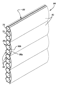
A third embodiment 84 of the present invention is illustrated in Figs. 7
and 8. In this embodiment, the headrail has not been illustrated but rather
only the fabric 86 which comprises a support structure 88 and a plurality of
interconnected slats 90.
With reference first to Fig. 7 and 7A, the support structure for this
embodiment comprises a plurality of superimposed and interconnected closed
cells 92 of hexagonal transverse cross-sectional configuration. The cells are
made of a semi-rigid material such as resin reinforced fabric or the like, and
can be formed in accordance with the teachings in U.S. Patent No. 6,572,725.
Each cell includes a top wall 94 and a bottom wall 96 with the bottom wall of
a
cell being secured, as with adhesive or the like, to the top wall of the next
adjacent lower cell. The cells further have side walls 98 having upper 98a
and lower 98b segments with fold lines between the segments of each side
wall so that the cells can be transversely compressed as shown in Figs. 7B-
7E. When referencing the cells as closed, it is in reference to the transverse
cross-sectional shape of the cell.
23
CA 02548617 2006-06-07
WO 2005/062875
PCT/US2004/043043
The slats 90, which are supported on the cellular support structure 88
are elongated rigid or semi-rigid slats of arcuate transverse cross-section
having an upper margin 100 that is secured to the upper segment 98a of the
front side wall 98 of an associated cell. The slat can be secured as with
adhesive or any other suitable means such as ultrasonic welding or the like.
In the disclosed embodiment, the slats are secured to every fourth cell so as
to protrude forwardly from the cellular support structure but when the
cellular
support structure is fully extended as shown in Figs. 7 and 7A, the slats hang
substantially vertically with the lower edge 102 of each slat slightly
overlapping the upper margin 100 of the next adjacent lower slat as shown in
Fig. 7A so that the cellular support structure is not visible from the front
of the
fully extended fabric.
While the fabric could be moved from the fully extended position of Fig.
7A to the fully retracted position of Fig. 7D or 7E in any suitable manner, a
lift
system is shown in dashed lines in Figs. 70 and 7E which would encompass
a plurality of vertically extending lift cords 104 supporting a bottom rail or
ballast 106 which would be positioned beneath the lowermost cell in the
support structure. By raising the lift cords and consequently the bottom rail,
each cell is caused to collapse transversely as the fabric is moved from the
fully extended position of Fig. 7A through a partially retracted position of
Figs.
7B and 70 to the fully retracted position of Figs. 7D and 7E. As will be
appreciated, in the fully extended position of Fig. 7 and 7A, the shade has
the
general appearance of a roman shade but when retracted as shown in Figs.
7D and 7E, the shade is very compactly stacked with the slats 90 protruding
forwardly away from the support structure 88. It should be noted that the
upper segment 98a of the cell, to which a slat is connected, serves as a lever
in moving the connected vane substantially unitarily therewith. In other
words,
as a cell is compressed during retraction of the covering, the acute angle of
the upper segment 98a relative to horizontal gets smaller thereby raising the
slat toward a horizontal orientation.
24
CA 02548617 2006-06-07
WO 2005/062875
PCT/US2004/043043
A slightly different arrangement is illustrated in Figs. 8A and 8B with
this arrangement having an identical support structure 88 to that of Figs. 7-
7F,
but the slats 108 are flat in transverse cross-section rather than arcuate.
Such an arrangement provides a different aesthetic.
Figs. 9A-9D illustrate a fourth embodiment of the invention very similar
to that of Fig. 7 wherein a support structure 88 in the form of a collapsible
cellular material supports a plurality of rigid or semi-rigid slats 110 off
the
upper segment 98a of the side wall of every fourth cell on the front side of
the
support structure. The embodiment of Figs. 9A-9D, however, has an
additional corresponding slat 112 on the rear side of the support structure
with
each rear slat being suspended from a corresponding top segment 98a of a
side wall of a cell on the rear side of every fourth cell as shown in Fig. 90.
The slats suspended from the front and rear of the support structure 88 are
identical and, as with the embodiment of Fig. 7, overlap the next adjacent
lower slat so that when the fabric is fully extended as shown in Figs. 9A and
9B, the cellular support structure is hidden from view. The structure is shown
in a fully retracted position in Fig. 90 and a lift system 114 of the type
previously described with the embodiment of Fig. 7 is shown in dashed lines.
Again, the top segment 98a of each cell to which a slat is connected serves
as a lever to raise the slat during retraction of the covering.
With reference to Figs. 10A-10D, a fifth embodiment of the invention is
shown similar to the embodiment of Figs. 9A-9D with a support structde 88 in
the form of collapsible interconnected hexagonal cells 92, but in this
embodiment there are rigid or semi-rigid slats 99 secured to the top
segment 98a of every third cell rather than every fourth cell and being
disposed on the front and rear of the support structure, respectively.
With reference to Figs. 11A-11D, a variation 116 of the invention is
shown similar to the embodiment of Fig. 7 with a support structure 88 in the
form of collapsible interconnected hexagonal cells 92 but in this embodiment
there are two sizes of rigid or semi-rigid slats 118 and 120 that are utilized
to
obtain a different aesthetic. The first slat 118 has an upper margin 122
CA 02548617 2006-06-07
WO 2005/062875
PCT/US2004/043043
secured to the top segment 98a of the front side wall of a cell with adhesive,
ultrasonic bonding or the like and is arcuate in cross section as in the
embodiment of Fig. 7 and overlaps three cells. The next adjacent lower slat
120, however, has a shallower depth than the first-described slat 118 but also
has an upper margin 124 secured to the top segment of the side wall of an
associated cell but this slat only overlaps two hexagonal cells rather than
the
three cells overlapped by the first or uppermost slat. Every other slat moving
downwardly is of the same size with the fabric so formed creating a different
aesthetic as viewed in the fully extended position of Figs. 11A and 11B and
the partially retracted positions of Figs. 110 and 11D. As will be appreciated
again, the top segment 98a serves as a lever in raising a connected slat
during retraction of the covering.
A sixth embodiment of the present invention is shown in Figs. 12A and
12B wherein the support structure is a double row of interconnected
hexagonal cellular structures with each row being identical to a hexagonal
structure 88 described previously but with each row being secured to the
adjacent row along contiguous faces such as where an upper segment 98a of
a cell engages a lower segment 98b of the next adjacent upper cell of the
adjacent row. In this embodiment, the slats are similar to those illustrated
in
Figs. 11A-11D wherein alternating slats 101 overlap either two or three cells,
respectively, with each slat being secured to the upper segment 98a of its
associated slat so that the upper segment 98a can serve as a lever in moving
the associated slat. The lower edges of each slat slightly overlap the upper
edge of the next adjacent lower slat so that when in the fully extended
position
illustrated in Figs. 12A and 12B, a double row cellular structure is hidden
from
view from one side of the fabric.
A seventh embodiment of the present invention is illustrated in Figs.
13A and 13B, which is similar to that of the sixth embodiment except the
support structure 88 is in the form of three rows of interconnected cellular
structures with each row having superimposed interconnected cells of
transverse hexagonal configuration and with each row interconnected with an
26
CA 02548617 2006-06-07
WO 2005/062875
PCT/US2004/043043
adjacent row along the upper segments of the cells where they engage with
the lower segment of the next adjacent upper cell of the adjacent row. Again
the slats 101, as in the sixth embodiment, alternate in size with every other
slat bridging two cells or three cells, respectively, and being connected
along
its upper edge to the upper segment 98a of an associated cell in a manner
such that the upper segment 98a serves as a lever in moving an associated
slat.
An eighth embodiment 256 of the present invention is illustrated in
Figs. 14A-14D. In this embodiment, the support structure 258 is in the form of
a pleated semi-rigid sheet of material which may be of the type found in
pleated shades for window coverings. The support structure thereby defines
forwardly downwardly sloped surfaces 260 as well as rearwardly downwardly
sloped surfaces 262. The slats 264 for this embodiment of the invention
comprise semi-rigid elongated strips of material of slightly arcuate
transverse
cross-section with each slat having an upper marginal zone 266 secured to a
lower marginal zone 268 of a forwardly downwardly sloped surface 260 of the
support structure. Fig. 14D shows the fabric 256 in a fully expanded position
where the pleated support structure can be seen to extend almost vertically
and with each slat overlapping the next adjacent lower slat and with the slats
themselves in combination defining a substantially planar wall parallel with
the
support structure while defining relatively thin cells 270 therebetween. Figs.
14A and 14B illustrate the fabric in a partially retracted condition with Fig.
14C
showing the fabric in a fully retracted position with the slats forming
substantially horizontal extensions away from the compressed support
structure. It should be appreciated that the surfaces 260 to which a slat is
connected serves as a lever in unitarily moving a slat therewith.
Figs. 15A-15D illustrate a variation 272 of the present invention that is
very similar to that illustrated in Fig. 14A wherein the support structure 258
is
again a pleated material of semi-rigid construction having horizontal fold
lines
to define forwardly downwardly 260 and rearwardly downwardly 262 sloped
surfaces. There are a set of semi-rigid slats 264 of slightly arcuate
transverse
27
CA 02548617 2006-06-07
WO 2005/062875
PCT/US2004/043043
cross-section having marginal zones 266 along their upper edges secured to
the forwardly downwardly sloping surfaces 260 and another set of identical
slats 264 secured to the lower edge of the rearwardly downwardly sloping
surfaces. The fabric is shown in a fully extended condition in Figs. 15A and
15D, and in a partially retracted condition in Figs. 15B and ,15D. In this
variation, the surfaces 260 and 262 serve as levers in moving associated slats
in unison therewith.
A ninth embodiment of the invention is illustrated in Figs. 16A-16C and
utilizes a sheet of flexible or semi-rigid material 304 as the support
structure
with the sheet of material being creased at 306 in opposite surfaces at
vertically spaced locations so the sheet of material will easily fold at the
crease line as shown best in Fig. 16B. The slats or vanes 308 are rigid or
semi-rigid and are connected to opposite sides of the support sheet and are of
arcuate transverse cross-section but have no tabs. Rather, the vanes are
secured directly to the associated side of the support sheet 304 immediately
above a crease 306. In this arrangement, when the fabric is fully extended,
which might be assisted by a weighted bottom rail 310, the fabric has the
appearance illustrated in Fig. 16A. The bottommost slat on the front face of
the sheet of support material overlaps the bottom rail 310 for aesthetic
purposes. As the weighted bottom rail is lifted, the bottom rail is drawn into
a
gap 312 between the lowermost slat on the front and rear face of the support
sheet causing the slats to flare outwardly in opposite directions and the
support sheet to fold in an accordion-like manner as viewed in Fig. 16C in a
partially retracted condition of the fabric. The sheet of material, along the
surface where a slat is connected, serves as a lever in moving the slats
during
extension and retraction of the covering.
A tenth embodiment 372 of the present invention is shown in Figs.
17A-17C. In this embodiment of the invention, the support structure 88 is
again formed from a plurality of interconnected semi-rigid cells 92 of
hexagonal transverse cross-section which are transversely collapsible and
wherein a plurality of rigid or semi-rigid slats 374 of arcuate transverse
cross-
28
CA 02548617 2006-06-07
WO 2005/062875
PCT/US2004/043043
section are secured to selected cells along one edge of the slat. The cells
have top 376 and bottom 378 walls that are interconnected by side walls
having upper 380 and lower 382 segments formed on opposite sides of
creased fold lines 384. The slats 374 are secured to an upper segment 380
of one side wall along one edge so as to overlap an adjacent slat along the
opposite edge when the fabric is extended as in Fig: 17A. The surfaces 380
to which a slat is connected serve as levers in moving the slats in unison
therewith. This fabric arrangement can be seen to be identical to that
illustrated in Fig. 7 except the fabric in Figs. 17A-170 is mounted
horizontally
and can be supported in a horizontal position within a framework 386 by
horizontal support rods 388 extending through the cells 92 of the support
structure. The fabric is shown in Fig. 170 in a fully expanded condition
across
the opening defined by the framework and as will be appreciated the slats
extend in substantially parallel relationship with the cellular support
structure.
When the fabric material is retracted, as shown in Fig. 17B, the cells are
transversely compressed and the slats hang downwardly therefrom in parallel
relationship.
Figs. 18A-18D illustrate another arrangement 312 similar to that of
Figs. 16A-160 except the support sheet 314 is preferably flexible and has not
been horizontally creased at vertically spaced locations, but again the slats
308 which are rigid or semi-rigid and arcuate in cross-section are secured to
the sheet at alternating locations on the front and rear of the sheet so the
fabric resembles that of Fig. 16A except the support sheet passes through
smooth curving lines rather than the folding lines established by the creases
306 of Fig. 16A. As in other embodiments, the sheet, at the locations where it
is connected to a slat, serves as a lever in moving the slats during extension
and retraction of the covering. Fig. 18D shows the fabric of Fig. 18A in a
partially retracted position with the slats flaring outwardly in opposite
directions and the support sheet folded in a zigzag pattern above the bottom
rail. Fig. 180 shows the fabric in a fully retracted position.
29
CA 02548617 2006-06-07
WO 2005/062875
PCT/US2004/043043
An eleventh embodiment 126 of the invention is shown in Figs. 19A-
19D where again the support structure 88 is in the form of superimposed
closed hexagonal cells which are transversely collapsible. Semi-rigid slats
128 are suspended from spaced cells off the front and rear face of the
cellular
support structure with each slat being of the same size and cross section.
Each slat 128 in cross-section, as best viewed in Figs. 19A and 19B, includes
upper 130 and lower 132 arcuate sections that are concave toward the
cellular support structure and have a crease line 134 between arcuate
sections. An upper marginal zone 136 of each slat is secured, as with
adhesive, ultrasonic bonding or the like, to the upper side wall 98a segment
of
a hexagonal cell with a lower marginal zone 138 secured in a similar manner
to the lower side wall segment 98b of a cell spaced downwardly four cells
from the cell to which the upper marginal zone is secured. Accordingly, along
the front face of the support structure, there are a plurality of slats made
of a
semi-rigid material which are secured to every fourth cell and a corresponding
set of slats on the rear face of the support structure with the slats on the
front
and rear of the support structure being concave inwardly toward the support
structure. The fabric comprised of the cellular support structure 88 and the
double-curved slats 128 is shown in a fully extended position in Figs. 19A and
19B, partially retracted in Fig. 19C, and fully retracted in Fig. 19D. As will
be
appreciated, as the cells are collapsed transversely the crease line 134
between the upper and lower arcuate sections of each slat allows the slat to
bend or flex inwardly so that the crease line becomes confined between two
cells of the support structure as they are partially and fully collapsed.
In a twelfth embodiment 140 of the invention illustrated in Figs. 20A-
20D, a cellular support structure 88 is again provided with the cells being
closed and of hexagonal transverse cross-sectional configuration. The slats
142 in this embodiment are semi-rigid strips of material mounted on the front
of the cellular support structure and the rear in confronting relationship.
Each
slat is identical having an upper marginal zone 144 secured in any suitable
manner to the upper segment 98a of the side wall of an associated hexagonal
CA 02548617 2006-06-07
WO 2005/062875
PCT/US2004/043043
cell and a lower marginal zone 146 secured between adjacent cells. In the
disclosed embodiment, the strip of slat material is secured at the upper
marginal zone to one cell and between the third and fourth cells therebeneath
along the lower marginal zone. In this manner, each pair of slats associated
with the same set of cells defines a closed cell 148 surrounding three cells
of
the cellular support structure even though as mentioned previously the closed
cells are only closed in transverse cross-section and are open on their ends.
When the fabric defined by the cellular support structure 88 and the
confronting pairs of semi-rigid slats 142 are moved from the extended position
of Figs. 20A and 20B through the partially retracted position of Fig. 200 to
the
fully retracted position of Fig. 20D, it will be appreciated that the slats
bulge
outwardly in both directions from the cellular support material and while
there
is some slight droop in the slat material, due to their semi-rigid nature,
they
project away from the cellular support material substantially horizontally.
A thirteenth embodiment 150 of the present invention is illustrated in
Figs. 21A-21D where it will be appreciated the support structure 88 is again
in
the form of a plurality of superimposed interconnected transversely
collapsible
hexagonal cells. A plurality of slats 152 are suspended from a front face of
the cellular support structure with an upper marginal zone 154 of each slat
secured to an associated upper segment 98a of the front side wall of an
associated cell and a lower marginal zone 156 of the same slat secured
between a pair of cells which in the disclosed embodiment are between the
third and fourth cells therebeneath that to which the upper marginal zone is
attached. The slats are made of a flexible material so as to droop off the
front
face of the support structure. As will be appreciated from Figs. 21A and 21B
which show the fabric in a fully extended position, Fig. 210 where it is
partially
retracted, and Fig. 21D where it is fully retracted, the slats always droop
from
the front face of the support structure to provide a different aesthetic from
that
of the fabric of Figs. 20A-20D.
A fourteenth embodiment 158 of a fabric in accordance with the
present invention is illustrated in Figs. 22A-22D. In this embodiment, the
31
CA 02548617 2006-06-07
WO 2005/062875
PCT/US2004/043043
support structure 160 is a cellular support structure with interconnected
cells
162 of quadrilateral transverse cross-section with each cell having a top wall
164, bottom wall 166, front wall 168, and rear wall 170. The top wall of one
cell is secured to the bottom wall of the next adjacent upper cell, as with
adhesive 172, so that the entire support structure is integrated with each
cell
being made from a flexible material. The vanes 174 associated with each cell
in this embodiment are formed from the same strip of material as an
associated cell in the support structure.
As is probably best appreciated by reference to Fig. 22D, each
cell/vane combination are formed by a strip of material that has a first edge
176 positioned in the top wall 164 of the cell adjacent to the front thereof
and
then drops downwardly to form the front wall 168 of the cell, then rearwardly
to form the bottom wall 166 of the cell, then upwardly to form the rear wall
170
of the cell, and finally horizontally to form the remainder of the top wall of
the
cell before dropping downwardly in front of the front wall of the cell and
then
inwardly and upwardly to form a looped vane 174 with the opposite edge 178
of the strip of material from which the cell/vane combination is made being
secured between the top wall 164 and the first edge 176 of the strip of
material. Of course, since the cell/vane combinations are made of a flexible
material, the vanes hang or droop downwardly across the front face of the
associated cells so as to overhang to a small degree the next lower adjacent
vane whereby in the fully expanded condition illustrated in Figs. 22A and 22B,
the cells in the support structure are shown as generally rectangular in
transverse cross section with a closed-loop drooping vane hanging across the
front of the associated cell from its top wall. When the fabric is moved to
the
fully retracted position of Fig. 22C, it will be seen that each cell in the
support
structure is fully collapsed transversely with the closed-loop vanes
projecting
from the front of the support structure.
A fifteenth embodiment 180 of a fabric in accordance with the present
invention is illustrated in Figs. 23A-23D. In this embodiment, the support
structure 182 is again a cellular support structure with each cell 184, as
best
32
CA 02548617 2006-06-07
WO 2005/062875
PCT/US2004/043043
seen in Fig. 23D, being formed from a single strip of material. The material
is
folded and creased so as to define a substantially flat front wall 186 with a
forwardly projecting crease 188 therein, a flat bottom wall 190, a pleated
rear
wall 192 composed of upper 192a and lower 192b segments above and below
a fold line 194 and a flat top wall 196 formed by tabs 198 and 200 extending
inwardly from the front wall and the rear wall respectively. The vanes 202 are
suspended from the front of the cellular support structure with each vane
being made of a semi-rigid material having an arcuate transverse cross-
section and a flat tab 204 that is inserted between the top wall 196 of an
associated cell and the bottom wall 190 of the next adjacent upper cell. The
tab 204 of course is adhesively or otherwise secured to the top wall tab 198
of
its associated cell and the bottom wall of the next adjacent upper cell. Each
slat is adapted to slightly overlap the next adjacent lower slat so as to
conceal
the juncture between adjacent cells.
A sixteenth embodiment 206 of the present invention is illustrated in
Figs. 24A-24E. In this embodiment, the support structure 208 as illustrated in
Fig. 24E is a plurality of superimposed cells 210 of quadrangular cross-
section which are transversely collapsible but when suspended as shown in
Fig. 24E assume a quadrangular, transverse cross-section which in the
illustrated embodiment is square. Each cell in the support structure has a top
wall 212, an identical bottom wall 214, a front wall 216, and a rear wall 218
that is the mirror image of the front wall. The front and rear walls have a
crease line therein forming an outwardly protruding rib 220 that extends
horizontally along the length of the cell so as to define upper 222 and lower
224 segments of each cell for the front and rear walls thereof. Fig. 240 '
shows a panel 226 of flexible vanes 228 which are interconnected such that
the entire panel can be secured to the support structure 208 in one of
numerous ways. In the illustrated arrangement, an upper marginal zone 230
of each vane has half 232 of a hook-and-loop type fastener such as Velcro
secured to a front face thereof while the reverse side of a lower marginal
zone
234 on the same strip has the same half 232 of a hook-and-loop material.
33
CA 02548617 2006-06-07
WO 2005/062875
PCT/US2004/043043
The reverse face of the top marginal zone 230 has a strip of the opposite half
236 of a hook-and-loop material so that the lower marginal zone of one strip
of vane material can be secured to the front face of the next lower strip of
vane material to form the panel 226 of interconnected strips. This panel of
interconnected strips of vane material can be secured to the support structure
such that the interconnected vanes are suspended from one face of the
support structure even though it will be appreciated that similar panels could
be suspended from both the front and rear faces of the support structure.
In Figs. 24A, the support structure 208 is shown with a strip of the
opposite 236 half of hook-and-loop material secured to the upper segment
222 of the front wall 216 of every other cell of the support structure (except
for
the two lowermost cells) so that the panel of interconnected vanes can be
releasably connected thereto by securing the upper marginal zone 230 of
each vane strip to an associated one of the attachment materials 236 on the
support structure so that the vanes 228 droop or hang downwardly as viewed
in Fig. 24D. It will also be appreciated that in the support structure
illustrated
in Fig. 24A, the lower two cells in the support structure each have the
fastener
material secured thereon so that when the panel of vanes is secured thereto,
the protruding loop of vane material protrudes further away from the support
structure to illustrate variations in use of this embodiment.
Fig. 24B illustrates the support structure 208 wherein the first-
mentioned half 232 of the hook-and-loop material covers one entire face of
the support structure so that the vane panel 226 can be secured in any
desired way to the front face of the support structure so the vane loops are
drooped in any desirable pattern. Obviously the hook-and-loop material could
also be placed on the rear face of the support structure if it was desired to
hang vane panels on both sides of the support structure. In addition, hook-
and-loop type fastener materials would not necessarily have to be used as
adhesives having the desirable release properties could be used or a
permanent adhesive or ultrasonic bonding could be used to secure the vane
34
CA 02548617 2006-06-07
WO 2005/062875
PCT/US2004/043043
panel to the support structure if the removable feature was not needed or
desired.
A seventeenth embodiment 238 of a fabric in accordance with the
present invention is illustrated in Figs. 25A-25C wherein the support
structure
240 is in the form of a plurality of superimposed interconnected open cells
242
having a pleated rear wall 244 defining upper 244a and lower 244b segments,
top 246 and bottom 248 walls, and a flap 250 forming the front wall which
hangs downwardly at an obtuse angle from the top wall. The slats 252
utilized in this embodiment are arcuate in transverse cross section and semi-
rigid with an upper marginal zone of 254 each slat being secured to the flap
250 on selected cells such that a lower edge of the slat overlaps the next
adjacent lower slat. In this disclosed embodiment, the slats are designed to
be connected to every other cell even though it will be appreciated that other
arrangements could be made consistent with the teachings in the present
application.
An eighteenth embodiment 274 of the fabric of the present invention
and its various arrangements is illustrated in Figs. 26A-26H and 26J-26L. In
this embodiment, the support structure is in the form of a sheet of material
276 such as sheer fabric or the like. The support sheet could have a
weighted bottom rail of various configurations but by way of example, in Fig.
26A, the bottom rail 278 is cylindrical in configuration or in Fig. 26J the
bottom
rail 280 is of arcuate transverse cross-section. With reference specifically
to
Figs. 26A-26D, the slats or vanes 282 in the fabric are slightly arcuate in
transverse cross-section and made of a semi-rigid material with a crease 284
spaced a short distance from the upper edge of the vane so the vane can be
folded to define a flap 286 as illustrated in Fig. 26D. Each vane can then be
secured in any suitable manner such as with adhesive, ultrasonic welding or
the like, to the support sheet 276 at vertically spaced locations with the
vanes
extending horizontally across the sheet. Each vane has a height such that it
slightly overlaps the next adjacent lower vane with the fabric being shown in
a
fully extended condition in Figs. 26A and 26B.
=
CA 02548617 2006-06-07
WO 2005/062875
PCT/US2004/043043
Figs. 26E and 26F illustrate an alternate arrangement but again where
the support structure is a sheet of material 276 such as sheer fabric but the
slats or vanes 288 rather than having a folded tab along the upper edge, are
simply secured to the fabric sheet with adhesive 290 or the like along a thin
line of connection so the slats bow outwardly away from the support sheet as
best seen in Fig. 26E.
Figs. 26G and 26H illustrate a system by which the slats 288 as used
in Fig. 26E can be made to appear flatter in arcuate cross-section and this is
accomplished by enlarging the line of adhesion 292 between the upper edge
of a slat and the support sheet 276 as shown best in Fig. 26H. Flattening an
arch in the slats is accomplished partly because of the semi-rigid nature of
the
slats but also through the width of the line of adhesion 292. As will be
appreciated, the bow or curvature in the slats can be varied depending upon
the width of the connection of the upper edge of the slat to the support
sheet.
Another arrangement 294 or variation off the embodiment of Fig. 26A,
26E, or 26G is shown in Fig. 26J where slats 288 are connected to both the
front and rear face of the support sheet of material 276 as in Fig. 26E with
the
adhesive attachment lines 290 of the slats on the front of the sheet being
offset from the attachment lines off the rear of the sheet but with the vanes
again overlapping the next adjacent lower vane. As will be appreciated, the
bottom rail 280, as mentioned previously, is of arcuate transverse cross-
section similar to that of the slats 288 to provide aesthetic continuity.
The fabric 294 illustrated in Fig. 26J can be rolled onto a roller 296
provided in a headrail 298 with the roller being of any conventional type used
in roller shades. As will be appreciated in Fig. 26K, the fabric is fully
extended
and depends from the roller while in Fig. 26L the fabric is completely
retracted
and wrapped around the roller. The semi-rigid nature of the slats 288 on the
flexible sheet of support material 276 allows the fabric structure to be
wrapped
on the roller and once unwrapped the slats will again expand to their original
configuration due to the resiliency of the semi-rigid material from which the
slats are made.
36
CA 02548617 2006-06-07
WO 2005/062875
PCT/US2004/043043
A nineteenth embodiment 300 and its variations of a fabric in
accordance with the present invention is shown in Figs. 27A, 27B, 27K-27N,
27P and 27S-27U. In this embodiment, the support structure is again a sheet
of flexible fabric material 276 which may have a weighted bottom rail 278.
The vanes or slats 282 for the fabric consist of semi-rigid strips of material
of
arcuate transverse cross-section having folded tabs 286 along their upper
edge identical to those illustrated in the embodiment of Fig. 26A. The vanes
are secured to the front and back face of the support sheet in any suitable
manner at vertically spaced locations along horizontal lines of connection
with
the vanes on each face slightly overlapping the next adjacent lower vane.
The vanes on the front face and rear face of the support sheet are mounted in
offset relationship with each other and wherein the lowermost vane on the
front of the sheet of fabric material hangs over the bottom rail 278 for
aesthetic reasons.
Fig. 27K shows another arrangement 316 of the fabric of the present
invention wherein the support structure is a plurality of horizontally spaced
vertically extending ribbons or tapes 318 of flexible material which again
could
be sheer fabric or other suitable material such as woven or nonwoven
materials. The vanes or slats 308 are semi-rigid and secured to the support
tapes identically to that of Fig. 27G and are of arcuate transverse cross-
section.
Still another arrangement 320 of the fabric of the invention is shown in
Figs. 27L and 27M with this arrangement being similar to that of Fig. 27K
except the ribbons or tapes of flexible material have been replaced with
monofilaments 322 or other suitable cords which may be of natural of
synthetic fibers. The support elements extend vertically and are horizontally
spaced with the slats 308 having a line of adhesive 324 adjacent their upper
edges so as to be secured to the support elements at vertically spaced
locations which alternate between the slats on the front and rear of the
support elements.
37
CA 02548617 2006-06-07
WO 2005/062875
PCT/US2004/043043
A further arrangement 326 of the present invention is shown in Figs.
27N-27U and in this arrangement the support structure is in the form of
conventional cord ladders 328 used in venetian blinds with an illustration of
such a cord ladder seen in Fig. 27U to include a pair of parallel vertical
riser
cords 330 and a plurality of vertically spaced horizontally extending rungs
332
interconnecting the riser cords. The slats 334 are rigid or semi-rigid and
arcuate in transverse cross-section having a pair of holes 336 adjacent to the
upper edge 338 of the slats at spaced locations along the horizontal length of
the slat aligned with the cord ladders. As is best appreciated by reference to
Fig. 271, the upper edge 338 of each slat has slots 340 interconnecting the
upper edge with each of the holes 336 to facilitate mounting of the slats on
the
cord ladders at each location of a rung in the cord ladder. In other words,
the
riser cords 330 are inserted through the slots 340 so as to be slidably
received in the holes 336 but the slat extending between the holes 336 will be
supported on the associated rung 332 to hold the slat in a desired position.
In
the arrangement illustrated, there are slats extending off the front and rear
side of the cord ladders with the slats on the front side alternating with
those
on the rear side from rung to rung. A weighted bottom rail 342 can be
secured to the bottoms of the cord ladders to keep the support structure
vertically extended.
A twentieth embodiment 344 of the invention is illustrated in Figs. 28A
and 28B which is very similar to the arrangement of Fig. 27G except slat S 308
are only mounted on one side of a flexible support sheet 314 which carries a
weighted bottom rail 346. The slats are mounted on the sheet at vertically
spaced horizontally extending locations with each slat slightly overlapping
the
next adjacent lower slat. The covering is shown mounted on a roller 348 as is
conventionally found in roller shades in the fully extended position in Fig.
28A
and partially wrapped around the roller in Fig. 28B. The resilient semi-rigid
nature of the slats allows them to be rolled around the roller but they will
resume their arcuate transverse cross-sectional configuration when unrolled
from the roller.
38
CA 02548617 2006-06-07
WO 2005/062875
PCT/US2004/043043
Figs. 29A and 29B illustrate a twenty-first embodiment 350 of the
present invention which is very similar to that of Fig. 26A except the semi-
rigid
slats 282 are mounted on a flexible support sheet of material 276 on both
sides of the support sheet of material with tabs 286 along the top edges of
each slat being secured in any suitable manner to the support sheet at
vertically spaced horizontally extending locations. The slats on the front
face
of the support sheet are mounted in alternating spaced locations from those
on the rear face of the support sheet and the fabric so formed is shown fully
extended and supported from a conventional roller for a roller shade in Fig.
29A and with that fabric partially wrapped around the roller in Fig. 29B.
Again,
the resilient semi-rigid nature of the slats allows them to fully expand and
resume their normal configuration once unrolled from a roller 352.
Figs. 30A and 30B illustrate a twenty-second embodiment 354 of the
present invention wherein a flexible support sheet 276 is suspended from a
roller 352 in a conventional manner and a plurality of slats 356 that are
arcuate in transverse cross-section are secured to the support sheet at
vertically spaced horizontally extending locations. The slats, however, have
their convex side facing the support sheet rather than the concave side as in
the previously described embodiments. The covering is shown fully extended
in Fig. 30A and partially wrapped around the conventional shade roller in Fig.
30B. Again, the resilient semi-rigid nature of the slats allows them to resume
their normal configuration once removed from the roller.
Fig. 31A shows a twenty-third embodiment 358 of the present invention
which is similar to that of Fig. 30A except there are slats 356 provided on
the
front and rear face of a support sheet 276 having a weighted bottom rail 360
and again with the slats having their convex side facing the support sheet.
The support sheet is again shown supported on a shade roller 362 in a
conventional manner.
Figs. 32A-32E illustrate a twenty-fourth embodiment 364 of the present
invention wherein the support structure 88 is illustrated as being
superimposed transversely compressible semi-rigid cells 92 that are
39
CA 02548617 2006-06-07
WO 2005/062875
PCT/US2004/043043
interconnected and are hexagonal in transverse cross-section. The vanes
366 in this embodiment are formed from a continuous sheet of flexible fabric
material 368 that is formed into a zigzag pattern having apexes 370 facing in
opposite directions and with each of the apexes facing in one direction
secured to the support structure 88 at spaced locations along the length of
the
support structure. In the illustrated embodiment, there are four cells 92
between each location where the vane material is secured. As will be
appreciated from the illustration, the fabric formed in this manner can be
mounted horizontally or vertically. Fig. 32E illustrates the fabric in a fully
expanded position, Figs. 32D shows the fabric in a partially retracted
position,
and Fig. 320 shows the fabric in a substantially fully retracted position.
Figs. 33A-33C illustrate a twenty-fifth embodiment of a fabric in
accordance with the present invention. In this embodiment, the support
structure 400 can be in the form of a continuous sheet, ribbons, cords,
microfibers, or the like to which slats 402 are attached at spaced locations
and alternately from the front and rear face of the support structure. The
slats
are elongated and disposed horizontally and in cross-section are shaped
similarly to half a tear drop. Each slat on the front of the fabric is adapted
to
slightly overlap the next adjacent lower slat on the front of the fabric and
the
same is true of the slats on the rear face of the fabric. A lift cord or cords
404
slidably extends vertically through the fabric and supports at its lower edge
a
horizontally disposed bottom rail 406 of circular transverse cross-section.
When the bottom rail is lifted as when the lift cord is raised upwardly, the
bottom rail gathers the support structure 400 and slats 402 as illustrated in
Fig. 33B. The half tear-drop shape of each slat is illustrated in Fig. 33C and
as will be appreciated by reference to Fig. 33A, a small marginal zone 408
along the top edge of each slat is secured to the support structure in any
suitable manner. The slats are preferably made of a rigid or semi-rigid
material. It should also be appreciated that the fabric would not necessarily
have to be gathered with a bottom rail as illustrated in Fig. 33B, but could
conceivably not include a lift cord and the entire support structure with
CA 02548617 2006-06-07
WO 2005/062875
PCT/US2004/043043
attached slats could be rolled about a roller (not shown) at the top of the
fabric
if desired.
Figs. 34A-34C illustrate a twenty-sixth embodiment of a fabric in
accordance with the present invention. As can be appreciated by reference to
Fig. 34A, the fabric includes a support structure 410 that could be in the
form
of a continuous sheet of material, strips of material, cords, ribbons,
microfibers, or the like to which a plurality of vertically spaced slats 412
are
mounted on the front and rear faces thereof. Each slat, as seen best in Fig.
340, is of a generally wavy configuration simulating the letter W turned on
its
side. Each slat has a marginal zone 414 along an upper edge thereof which
is attached to the front or rear face of the support structure and with the
slats
along the front and rear of the support structure overlapping the next
adjacent
lower slat and being alternated with slats on the other side of the support
structure. A lift cord 416 could be extended downwardly through the support
structure terminating in a weighted bottom rail 418 so that when the lift cord
is
raised upwardly, the bottom rail would engage the lowermost slats in the
fabric and as the lower rail is further raised, gather the slats thereabove
into a
completely retracted condition as shown in Fig. 34B. It would not be
necessary to use the lift cord', however, as the fabric could in fact be
wrapped
around a roller (not shown) positioned at the top of the fabric as has been
described with previous embodiments. The slats would preferably be made of
a rigid or semi-rigid material.
Figs. 35A-35C illustrate a twenty-seventh embodiment of a fabric in
accordance with the present invention. In this embodiment, a support
structure 420 in the form of a sheet of material, ribbons, cords, microfibers,
or
the like supports overlapping slats 422 on the front and rear faces thereof.
The slats as best seen in Fig. 350 resemble a flattened letter V turned on its
side and define a marginal zone 424 along the upper edge which can be
secured to the support structure. The slats on both the front and rear faces
overlap the next adjacent lower slat and are alternated with slats on the
opposite face of the support structure. The slats would preferably be made of
41
CA 02548617 2006-06-07
WO 2005/062875
PCT/US2004/043043
a rigid or semi-rigid material. A lift cord 426 could be extended downwardly
through the support structure terminating in a weighted bottom rail 428 so
that
when the lift cord was raised, the bottom rail would accumulate the slats and
when the fabric was fully retracted it would assume the position illustrated
in
Fig. 35B. The lift cord would not be necessary, however, as the fabric could
be attached at its upper end to a roller (not shown) whereby it could be
rolled
into a retracted position.
Figs. 36A and 36B illustrate a shade for an architectural opening in
accordance with the present invention which is hybrid in incorporating two
lo different components of fabric material. The shade as best seen in Fig.
36A
would be suspended from a headrail 430 into which it could be retracted with
the fabric 432 including an upper component 434 and an interconnected lower
component 436. The upper component is illustrated as having a support
structure 438 in the form of a sheet of material but could be ribbons, cords,
microfibers, or the like. The support structure has supported on both front
and
rear faces thereof elongated slats 440 of arcuate cross section with the slats
being connected to the support structure along an upper edge 442 and with
each slat overlapping the next adjacent lower slat. The slats on the front
face
of the support structure are alternated with slats on the rear face as in
previously described embodiments. The upper component 434 terminates at
its lower edge in a weighted lift rail 444 which may be suspended by lift
cords 446 so that as the weighted rail is raised by the lift cords, the slats
440
are accumulated on the lift rail as in previously described embodiments. The
lift rail in turn supports the lower component 436 of the fabric which is
illustrated as a sheet of flexible material 447 that could be a sheer fabric
or
the like, with the sheet of material being connected along its lower edge to a
roller 448. The roller could be a spring-biased roller of the type found in
some(
retractable roller shades or could be a spring balanced roller which would
allow the roller to be manually raised to and maintained at any location
across
the sheet of material. It will therefore be appreciated that the shade could
be
a bottom-up type shade suspended from the upper headrail 430 as illustrated
42
CA 02548617 2006-06-07
WO 2005/062875
PCT/US2004/043043
or the roller 448 could be attached adjacent to the bottom of an architectural
opening leaving the top edge of the fabric free to move up and down so that
the shade is a top-down type shade which could be lowered from the top edge
toward the roller 448 in any conventional manner. It will be appreciated from
the above that the fabric for the shade could incorporate numerous
combinations of fabric components and even more than two different
components could be utilized.
As an alternative to the hybrid shade shown in Figs. 36A and 36B, a
different hybrid shade 450 is illustrated in Figs. 37A and 37B. In this hybrid
shade, a headrail 452 supports an upper component 454 of the hybrid fabric
which is an interconnected cellular fabric of the type described previously
with
other embodiments, and the lower component 456 is the same as the upper
component disclosed in the hybrid shade of Fig. 36A. In this arrangement, a
lift cord 458 would extend vertically from the headrail downwardly to a
weighted bottom rail 460 which would allow the hybrid fabric to extend by
gravity but could be retracted by raising the bottom rail with the lift cord.
This
shade is simply another illustration of ways of combining different fabrics
some or all of which may be of the type disclosed in this invention to make a
single shade for an architectural opening.
Figs. 38A and 38B illustrate a control system for a shade wherein the
fabric 462 used in the shade could be, for example, of the type illustrated in
Figs. 1-4. The control system is of a top-down/bottom-up type. The shade
would include a headrail 464 that would be mounted adjacent to the top of an
architectural opening to partially house a control system that would be
anchored to a bottom frame member or sill 466 of the architectural opening.
The shade would include an upper movable rail 468 and a lower movable
rail 470 and a fabric 472, for example, of the type disclosed in Figs. 1-4
extending between the upper and lower movable rails. A pair of pull
cords 474 and 476 in the control system operate the shade with one pull
cord 474 extending from a tassel 478 at the right side of the shade upwardly
around a pulley 480 at the right end of the headrail 464, then horizontally
43
CA 02548617 2006-06-07
WO 2005/062875
PCT/US2004/043043
around a right one 482 of a pair of centered pulleys of the headrail and
downwardly from the right centered pulley to an anchor 484 in the upper
movable rail 468. It will therefore be appreciated that pulling downwardly on
the right tassel 478 would raise the upper movable rail while raising the
tassel
would allow the upper movable rail to drop by gravity. A conventional brake
system (not seen) could be incorporated into the pulley 480 at the right end
of
the headrail to lock the right lift cord and thus the upper movable rail in
any
desired position.
The left lift cord 476 commences with a tassel 486 at the left side of the
shade and extends upwardly around a left side pulley 488 which could
incorporate a conventional releasable lock system (not seen), horizontally and
around the left one 490 of the centered pair of pulleys and then downwardly
along the center of the shade to pass around a series of three guide
pulleys 492 to an anchored location 494 on the lower movable rail 470. It will
'therefore be appreciated that a downward pull on the left tassel 486 would
raise the lower movable rail 470 and raising the left tassel would allow the
lower movable rail to drop by gravity. Of course, the lock in the pulley 488
could secure the lower movable rail at any desired vertical position. The
lower vertical rail, when raised relative to the upper movable rail, is used
to
gather or accumulate the slats in the fabric so whether or not the lower
movable rail is raised or the upper movable rail is lowered, the slats can be
gathered as described in connection with Figs. 1-4 on the lower movable rail.
Figs. 39A-39C and 40-44 illustrate an arrangement of a fabric of the
type described, for example, in Figs. 1-4 wherein the architectural
opening 496 in which the shade is mounted has a semi-circular top edge 498.
A fabric 500 formed as described in connection with Figs. 1-4, for example,
having a support structure 38 and slats 42 would be cut to conform with the
shape and size of the architectural opening so that the top edge 502 of the
fabric is also of a semi-circular configuration. A lift cord 504 having a
tassel 506 at one end would extend into an opening 508 (Fig. 40) in one side
of the frame around the architectural opening and be slidingly confined within
44
CA 02548617 2006-06-07
WO 2005/062875
PCT/US2004/043043
a groove 510 (Fig. 40) in the frame and subsequently pass out of the
framework at a centered location in the semi-circular top edge 498 of the
architectural opening. From there the lift cord would extend downwardly for
attachment to a centered location on the top edge 502 of the fabric. Pulling
the tassel 506 downwardly would therefore raise the top edge of the fabric
while allowing the tassel to move upwardly would permit the fabric to drop by
gravity downwardly from the fully extended position of Fig. 39 through an
intermediate position as shown in Fig. 39B to a substantially fully retracted
position as shown in Fig. 390. A conventional lock (not seen) for the pull
cord
could be incorporated into the framework for the architectural opening so the
fabric could be releasably positioned at any desired position within the
architectural opening. The framework for the architectural opening would
have a ledge or sill 512 along the lower edge thereof on which an I-beam type
accumulating rail 514 as shown in Fig. 41 could be mounted and to which the
lower edge of the fabric 500 would be attached. This rail would provide a
structure on which the slats in the fabric could accumulate as the fabric was
lowered with the lift cord and off which the fabric could be lifted as the
lift cord
raised the upper edge of the fabric toward the top of the architectural
opening.
As an alternative to the I-beam accumulating rail 514 shown in Fig. 41,
a rail 516 of ovular cross-sectional configuration could be provided of the
type
shown in Figs. 42-44. This rail could be made of a semi-rigid pre-creased flat
piece of material 518 as illustrated in Fig. 44 wherein the strip of material
has
a main portion 520 and a base portion 522 defined by a crease 524 which
defines a fold line with the base portion being secured, for example, on its
undersurface to a strip of double-faced adhesive 526. The edge 528 of the
main portion 520 opposite the base portion 522 could define a flap 530 having
a strip of double-faced adhesive 532 so the main portion could be folded
through a generally egg-shaped loop as shown in Figs. 42 and 43 and
secured to the opposite side edge 534 of the base from where the main
portion 520 is pivotally connected to the base 522. In reality, the pivotal
connection would simply be a crease and a similar crease would be defined
'
CA 02548617 2006-06-07
WO 2005/062875
PCT/US2004/043043
between the main portion and the flap. The accumulator rail 516 when
desirably folded would have a look as shown in Fig. 43 and could then be
adhesively stuck to the sill 512 of the architectural opening as shown in Fig.
42 and define an aesthetically pleasing gathering rail to which the lower edge
of the fabric is secured and on which the fabric for the shade could be
accumulated or removed depending upon whether or not the shade is
retracted or extended respectively.
Figs. 45-47 disclose still another use of a fabric in accordance with the
present invention which may be of the type described, for example, in Figs. 1-
4 and in this arrangement, four identical shade components 536 are mounted
in one architectural opening 538 in vertically aligned relationship. Each
shade
component would be, for example, of the type shown in Figs. 1-4 so that its
fabric component 540 could be raised or lowered across the portion of the
architectural opening to which it is associated. Each shade could be operated
independently or in unison by either leaving the lift cords for the shades
separate or by combining the lift cords, respectively. Fig. 45 shows all four
, shade components fully extended so that the entire architectural opening is
covered by slats. Fig. 46 shows each shade component partially extended.
Fig. 47 shows each shade component fully retracted. Of course, when fully
retracted, the headrail 542 for each shade component would still be visible.
Figs. 48A and 48B illustrate the fact that a fabric in accordance with the
present invention and such as, for example, the embodiment shown in Figs.
1-4 could be mounted in an architectural opening 543 of a triangular
configuration. The fabric 544 would be cut into a shape and size
commensurate with the opening in which it is to be mounted and an
accumulating rail (not seen) could be positioned along the base of the
triangular opening to which the lower edge of the fabric 544 is attached. A
lift
cord 546 would be connected to the top edge or apex 548 of the fabric so the
apex could be raised or lowered allowing all the slats thereunder to be
removed from the accumulating rail or accumulated thereon in a fully retracted
46
CA 02548617 2006-06-07
WO 2005/062875
PCT/US2004/043043
position. Of course, Fig. 48A shows the shade fully extended across the
opening and Fig. 48B shows the shade partially extended.
Figs. 49A and 49B illustrate another use for a shade in accordance
with the present invention and which again could be of the type disclosed in
Figs. 1-4 with this embodiment having upper 550 and lower 552 shade
components and accumulating rails 554 and 556, respectively, associated
therewith across the vertical center of a circular opening 557 in which the
shade is mounted. The upper and lower shade components are cut in semi-
circular configurations and inverted relative to each other. Operating
cords 558 and 560, respectively, are attached to vertically aligned centered
locations at the top and bottom of the upper and lower respective shade
components. Fig. 49A shows both shade components fully extended but
when retracted, the pull cords would be operated to draw the top and bottom
edges of the upper and lower shade components, respectively, toward a
centered horizontal location in the architectural opening (Fig. 49B) where the
accumulating rails would face upwardly and downwardly to receive the slats in
stacked relationships. In other words, the fabric material would extend away
from the vertically centered, horizontally extending accumulating rails when
the shade was being moved from a retracted to an extended position.
Obviously, either the upper shade component or the lower shade component
could be operated independently if desired.
Figs. 50A and 50B illustrate a shade in accordance with the present
invention, which could again be of the type shown in Figs. 1-4, mounted in an
architectural opening 561 in the shape of a right triangle having a vertical
side,
a lower base side perpendicular thereto and a hypotenuse. The fabric 562 for
the shade would be cut in the same size and shape as the opening and would
have its slats oriented horizontally. A mounting rail (not seen) would be
mounted on the base of the triangle to which the lower edge of the fabric
would be connected and onto which the slats could accumulate when the
shade was retracted by allowing the slats to drop by gravity onto the
accumulating rail. A lift cord 564 would be incorporated into the vertical
side
47
CA 02548617 2006-06-07
WO 2005/062875
PCT/US2004/043043
of the fabric so as to lift the apex 566 of the fabric upwardly when extending
the shade or lower the apex when retracting the shade onto the accumulating
rail.
Figs. 51A and 51B illustrate still another possible use of a fabric in
accordance with the present invention with the fabric again possibly being of
the type illustrated in Figs. 1-4. In this use, there are three adjacent
architectural openings 566, 568, and 570 in which independent shades 572,
574, and 576, respectively, are mounted while each of the shades are shown
as bottom-up type shades, they could be reversed so as to be top-down type
shades or a top-down/bottom-up type shade. In the illustrated bottom-up
arrangement, each shade might have a lift rail (not seen) mounted above at
578, but near, a lower contoured edge 580 of the fabric of each shade. The
lower edge of each fabric is contoured in a complementary manner to the
adjacent fabrics so that when the fabrics are positioned in selected
positions,
a continuous non-linear contour of the three combined shade components is
established. In Fig. 51A, each fabric component is shown substantially
extended across the architectural opening in which it is mounted while in Fig.
51B each shade component is substantially retracted. It should also be
appreciated that since the bottom rail for each shade is not along the bottom
edge of the fabric but rather just above the lower contoured edge, the shades
are never fully retracted but look as shown in Fig. 51B when substantially
fully
retracted so as to always show the lower contoured edges. As an alternative,
the shades could be mounted on rollers in a headrail so as to be fully
retractable.
Figs. 52-736 are directed to a further arrangement of the shade of the
present invention wherein a fabric of the type shown in the embodiment of
Fig. 1 is incorporated into a system that does not include rollers or lift
cords
for moving a bottom rail upwardly or a top rail downwardly in the operation of
the shade. Rather, the embodiment of Figs. 52-736 includes a fabric 590 of
the type shown in Fig. 1 incorporated into a system with a rail that is
manually
movable with a handle connected directly to the rail between extended and
48
CA 02548617 2006-06-07
WO 2005/062875
PCT/US2004/043043
retracted positions. As will also be appreciated with the description that
follows, this arrangement of the invention can be made into a top down
system, a bottom up system, or a top down/bottom up system. Further, as will
be appreciated from the description that follows, the arrangement can utilize
a
top rail, bottom rail, and midrail(s) which are uniformly designed but can be
mounted in different orientations depending upon their use in the covering.
With reference first to Fig. 52, the covering can be seen to include a
top rail 592 that is securable in an architectural opening with end
brackets 594, a bottom rail 596 that is also securable in the architectural
opening (not shown) with end brackets 594 which may be identical to those
supporting the top rail 592, and a midrail 598. The top rail and bottom rail
anchor the ends of two vertically extending guide cords 600 which are
disposed near the ends of the rails with the guide cords being operatively
connected to the midrail 598 as will be described hereafter so that the
midrail
can be moved vertically to any selected position with a manually gripable
handle 602 that is secured thereto. The fabric 590 for the covering is
suspended along its top edge from the top rail 592 and anchored along its
bottom edge to the midrail 598 so that when the midrail is raised, as
illustrated
in Fig. 53, the fabric material is accumulated adjacent to the top of the
material and when lowered the fabric is expanded across the architectural
opening. The midrail can be positioned adjacent to the bottom rail similarly
to
Fig. 52, or with the midrail lowered even further so that the bottom vane 604
of the fabric overlaps the bottom rail.
The mounting brackets 594 which might best be seen in Figs. 54, 57,
and 58 are universal and are interchangeable between use for supporting the
top rail 592 and/or the bottom rail 596. Each bracket has a base 606 with
perpendicular vertical walls 608 having holes therethrough for receiving
fasteners that anchor the bracket to the framework around the architectural
opening. The bracket further has a tongue 610 extending from the base and
a curved securement finger 612 lying thereover. The tongue is adapted to
receive an insert 614 at the associated end of a top or bottom rail as will be
49
CA 02548617 2006-06-07
WO 2005/062875
PCT/US2004/043043
described later. The bracket can be mounted either horizontally as shown in
Figs. 57 and 58 or vertically as shown at the top of Fig. 55.
As mentioned previously, each of the top 592, bottom 596, and
midrails 598 are of identical construction and as probably best seen in Figs.
52, 52B, 52G, and 52H, are extruded members of generally H-shaped
transverse cross section so as to define an upper groove 616 with
overhanging lips 618, a bottom groove 620 with overhanging lips 622, and a
center groove 624 that opens through a rear wall 626. A notch 628 is formed
in the front wall 630 that also has overhanging lips 632 and as will be
appreciated in Fig. 52B, the height of the rail is greater than the width. For
purposes of the present disclosure, the orientation shown in Fig. 52B will be
referred to as a vertical orientation of the rail. When the rail is turned 90
degrees in either direction, it will be referred to as a horizontal
orientation. By
way of example, with reference to Fig. 52, the top rail 592 and the midrail
598
are both vertically oriented, and the bottom rail 596 is horizontally
oriented.
With reference to the top rail 592 as shown in Fig. 52B, the top 616 and
bottom 620 grooves are devoid of any operative components except that they
receive the previously mentioned inserts 614. The notch 628 in the front wall
is used to anchor the top edge of the support members 38 in the fabric 590
with an anchor strip 634 that is secured to the support members with a strip
of
adhesive 636. The anchor strip is flexible and confinable behind the inturned
lips 632 of the notch 628 so that the top of the fabric is anchored to the
front
of the top rail with the uppermost vane 42 abutting the upper lip 632 of the
top
rail so as to essentially cover the top rail from view. A guide cord 600 is
also
seen in Fig. 52B as passing through the center groove 624 in the top rail
member as will also be described in more detail hereafter.
As is probably best seen in Fig. 55, and as mentioned previously, there
are two guide cords 600 each having one end anchored in the top rail 592 and
an opposite end in the bottom rail 596 with an intermediate portion of each
guide cord passing slidably through the midrail 598. The top ends of the
guide cords are interconnected with a coil spring 640 seated in the center
CA 02548617 2006-06-07
WO 2005/062875
PCT/US2004/043043
groove 624 and pass through the center groove in the top rail in opposite
directions so as to extend through the inserts 614 at the ends of the top
rail,
then downwardly and into the insert 614 at the associated end of the
midrail 598 where each cord extends laterally across the covering and
through the insert 614 at the opposite end of the midrail before extending
downwardly and into the insert 614 at the associated end of the bottom
rail 596 and subsequently inwardly toward the opposite end of the bottom rail.
Finger clamps 642, which will be described in more detail later, secure the
lower ends of the guide cords to the bottom rail.
Referring to Fig. 54, the midrail 598, top rail 592, and bottom rail 596
have been incorporated into the skeletal system shown in Fig. 55 and as will
be appreciated, the midrail can be moved upwardly or downwardly and
through friction of the guide cords with the inserts 614 at the end of the
midrail
and support of the midrail by the guide cords, the midrail will remain in any
position in which it is placed. The handle 602 mentioned previously, which is
secured to the midrail, as will be described later, is used to move the
midrail
up or down so as to position it in any desired location.
The covering shown in Figs. 52-56 is a bottom up system wherein the
midrail 598 is positioned adjacent to the bottom rail 596 when the covering is
fully extended but adjacent to the top rail 592 when the covering is fully
retracted. Figs. 520 and 52D as well as Figs. 52E and 52F illustrate the
passage of the guide cords 600 through the top rail, middle rail, and bottom
rail and their interconnections therewith. With regard to Figs. 52E and 52F,
and with further reference to Figs. 52G, 52H, 521, and 52K, the finger clamps
or locks 642 are elongated bodies having pivot arms 644 and a pair of
transverse passages 646 at one end through which a guide cord can be
reversibly extended to hold it in place on the finger lock. The finger lock is
adapted to be slid into the end of the upwardly opening groove 616 in the
bottom rail and can be positioned at any location along the length of the
bottom rail when the finger lock is vertically oriented as shown in Fig. 52F.
In
other words, the fingers will slide in the upwardly opening groove when
51
CA 02548617 2006-06-07
WO 2005/062875
PCT/US2004/043043
vertically oriented as in Fig. 52F but can be pivoted about the pivot arms 644
into the position of Fig. 52E to pinch the guide cord 600 within the upwardly
opening groove and hold the finger lock in a locking position. Fig. 52G shows
the guide cord being pinched at the pivot arm end thereof and unpinched
adjacent the opposite end of the lock finger. Of course, the lock fingers are
positioned along the length of the bottom rail at a position to obtain a
desired
tension in the guide cords which should be sufficient to retain a dependable
vertical orientation of the cords as they extend between the top and bottom
rails and through the midrail so that the midrail can be easily slid along
their
length in moving the covering between extended and retracted positions.
The previously mentioned inserts 614 for the ends of the rails are
probably best illustrated in Figs. 56-58 and can be seen to have an enlarged
hollow projection 648 for receipt in an open end of the center groove 624
through an associated rail, and smaller projections 650 for receipt in the
upper 616 and lower 620 grooves of the rail with the projections being sized
to
frictionally fit within the grooves of the rail to be releasably retained
therein.
The opposite end of each insert has bifurcated legs 652 defining a slot 654
therebetween that receives the tongue 610 of the associated mounting
bracket 594. The exploded view of Fig. 57 probably best illustrates the insert
with a mounting bracket and once in place on the tongue, is prevented from
easy removal by the overlying curved securement finger 612 as seen in Fig.
58. Fig. 56 is also illustrative of the interconnection of the top of the
fabric 590
to the front groove or notch 628 in the top rail as described previously. The
inserts are made of a somewhat rigid material.
The handle 602 used to raise or lower the midrail 598 in operation of
the covering is probably best seen in Figs. 54 and 55 to include an upstanding
back wall 656, a horizontal forwardly extending lower flange 658 and an
integral horizontal rib 660 along the top of the back wall which can be
slidably
received in the downwardly opening groove 620 of the midrail so as to be
supported therefrom. The back wall 656 also has downwardly and forwardly
flaring ribs 662 adapted to confine a bottom edge of a dummy vane 664 (Fig.
52
CA 02548617 2006-06-07
WO 2005/062875
PCT/US2004/043043
56, 73A, and 73B) in the fabric material to hold the dummy vane in a desired
orientation as will be explained later. An arcuate finger tab 666 projects
forwardly from the flange 658 in a position where it can be gripped by an
operator of the covering at a location outwardly from the fabric 590 as
probably best seen in Fig. 53.
From the above, it will be appreciated the midrail 598 can be moved
between any desired position with the handle 602 and will retain any position
in which it is placed due to the friction of the midrail with the guide cords
600
and the support of the guide cords. The spring 640 interconnecting the top
ends of the guide cords is of sufficient strength to provide desired tension
in
the guide cords as is also determined by the positioning of the finger
locks 642 in the bottom rail. As in the previously described uses of the
fabric,
when the midrail is raised, the fabric 590 will gather and be supported on the
midrail and as the midrail is lowered, the fabric will become unstacked and
distributed vertically across the architectural opening from the top rail to
the
midrail regardless of its position.
Referring to Figs. 59-62, the same components described with regard
to the arrangement of Fig. 52 are utilized in a top down shade by anchoring
the lower end of the fabric material 590 to the bottom rail 596 similarly to
the
manner in which the top edge of the fabric was anchored to the top rail 592 in
the embodiment of Fig. 52. The top edge of the fabric is in turn anchored to
the front of the midrail 598. An inverted handle 668 having simply a finger
tab 670 with a horizontal rib 672, for retention in the top groove of the
midrail,
is provided for movement of the midrail. The guide cords 600 are also
reversely mounted so that the finger locks 642 are in the top rail 592 and the
coil spring 640 in the bottom rail 596 but again pass through and along the
length of the midrail so that the midrail can be positioned at any location
between the top and bottom rails to move the covering between extended and
retracted positions. As shown in Fig. 59, the midrail has been fully elevated
so as to fully extend the covering across the architectural opening whereas in
53
CA 02548617 2006-06-07
WO 2005/062875
PCT/US2004/043043
Fig. 60, the midrail has been lowered adjacent to the bottom rail to retract
the
awning relative to the architectural opening.
Figs. 61 and 62 show the guide cords 600 with the finger locks 642
being in the top rail 592 and the coil spring 640 in the bottom rail 596 and
the
handle 668 on the intermediate rail 598. The handle, as mentioned
previously, is raised slightly so that a back plate is not necessary but
rather
only the rib 672 which is slidably secured in the open groove 616 along the
top of the midrail for attachment of the handle to the midrail.
Figs. 63-66 show an arrangement of the covering of Fig. 52 wherein it
functions as both a top down and a bottom up covering. In this arrangement,
as probably best illustrated by reference to Fig. 66, there are two sets of
guide
cords 600 on each side of the covering with one set having its upper ends
secured in the top rail 592 with finger locks 642 and its lower ends to a coil
spring 640 in the bottom rail 596 while the opposite set has its lower ends
secured to the bottom rail with lock fingers and its top ends to each other in
the top rail with a coil spring. The cords 600 pass in reverse directions
through an upper midrail 598U and a lower midrail 598L as they extend
between the top and bottom rails. The upper midrail has a handle 668 of the
type used in the embodiment of Fig. 59 while the lower midrail has a
handle 602 of the type used in the embodiment of Fig. 52. The fabric 590 is
anchored at its upper end to the upper midrail 598U and at its lower end to
the
lower midrail 598L in the manner 'described previously in connection with the
embodiment of Fig. 52. As can be appreciated by reference to Figs. 64 and
65, the upper midrail can be lowered toward the lower midrail allowing the
fabric to accumulate on the lower midrail or the lower midrail can be raised
relative to the upper midrail again allowing the fabric to gather on the lower
midrail. The covering can therefore be fully retracted adjacent the top rail
or
fully retracted adjacent the bottom rail or positioned at any degree of
extension at any location between the top and bottom rails.
Figs. 67-69 show still another use of the covering of the type shown in
Fig. 52 wherein a pair of guide cords 600 are anchored at the top of an
54
CA 02548617 2006-06-07
WO 2005/062875
PCT/US2004/043043
architectural opening in any suitable manner such as with fasteners 674
shown diagrammatically in Figs. 67 and 68. The guide cords extend
downwardly and are anchored in a bottom rail 596 with the finger locks 642 in
the manner described previously. In their downward passage, each guide
cord crosses to the opposite side through the midrail 598 which has a
handle 668 anchored in the upper groove 616 thereof so that the midrail can
be raised or lowered. In the embodiment illustrated in Figs. 67-69, the
covering is a top down covering even though it will be appreciated that the
reverse could be accommodated in a manner which would be well known to
those skilled in the art. It will also be seen that the bottom rail is
supporting a
dummy vane 664 from its bottom groove 620 with the dummy vane being
fabricated to simulate each of the vanes 42 in the fabric 590 except that it
is of
tubular construction as will be described in more detail later.
Fig. 70 shows another arrangement utilizing the fabric 590 of Fig. 1
wherein a pair of vertically suspended guide cords 600 support the fabric with
the guide cords being anchored with fasteners (not shown) to the top of the
framework around an architectural opening. The covering includes a top
rail 592 identical to that shown in Fig. 52 with the top edge of the fabric
connected to the top rail in the manner previously described and further
including a handle 668 of the type utilized in the embodiment of Fig. 59. The
covering of Fig. 70 includes a dummy vane 664 along the bottom thereof
which is overlapped by the lowermost vanes 42 on the front and back of the
fabric in the covering. The dummy vane is anchored to the bottom ends of the
guide cords in a manner to be described hereafter and is weighted so as to
retain the fabric for the covering in a vertically extended somewhat taut
position when the top rail 592 is raised relative to the dummy vane as shown
in Fig. 70. The top rail can be lowered by gripping the handle 668 and pulling
the top rail downwardly so that it slides along the guide cords as described
previously in connection with Fig. 52. As the covering is retracted by
lowering
the handle connected to the top rail, the vanes accumulate on the dummy
vane. The dummy vane is probably best illustrated in the exploded views of
CA 02548617 2006-06-07
WO 2005/062875
PCT/US2004/043043
Figs. 73A and 73B to include an extruded base 676 having an upwardly
opening groove 678 along its top edge with overhanging lips 680 in which
finger locks 642 of the type previously described can be anchored to secure
the lower ends of the guide cords. The extruded base further has a
downwardly opening groove 682 for a purpose to be described hereafter and
downwardly flared side walls 684 to confine a generally V-shaped semi-rigid
strip 686 that can be attached to the extruded base to define the desired
contour of the dummy vane. A ballast bar 688 is slidably positionable within
the downwardly opening groove by inserting the ballast bar into one end of
the groove 682. Spring-biased clips 690 are slidably inserted into the same
groove 682 at opposite ends of the ballast to retain the ballast in a desired
position. Movement of the ballast along the length of the base and positively
positioning it encourages the fabric in the covering to hang vertically as
desired. If the fabric is skewed in its natural suspension, proper positioning
of
the ballast will facilitate straightening of the fabric for aesthetic
purposes.
The generally V-shaped strip of semi-rigid material 686 can be affixed
to the base 676 with adhesive or any other suitable means or can be provided
with barbs or tabs 692 as shown in Fig. 73B which are adapted to catch on
ridges 694 formed along the outside walls of the downwardly opening
groove 682 with the sides of the V-shaped strip confined by the downwardly
flared side walls 684. In other words, inserting the top edges of the tubular
strip into the gap between the flared sides of the base and the walls of the
downwardly opening groove so that the barbs catch on the ridges, the tubular
strip is reliably secured to the base and suspended therefrom.
Identical end caps 696 of generally ovular configuration are insertable
into the open ends of the extruded base 676 and the strip material 686 with
,
the end caps including a large projection 698 along a lower portion that
inserts
into the associated open end of the strip material and a pair of protrusions
700
adjacent to the top which are frictionally received in the upwardly opening
678
and downwardly opening 682 grooves of the base.
56
CA 02548617 2006-06-07
WO 2005/062875
PCT/US2004/043043
With reference to Figs. 74-95, an embodiment of the invention similar
to that shown in Figs. 52-73B is illustrated. This embodiment is similar to
that
of Figs. 52-73B in that the shade incorporates a fabric 590 of the type shown
in the embodiment of Fig. 1 and again does not include rollers or lift cords
for
moving a bottom rail upwardly or a top rail downwardly in the operation of the
shade. Rather, the fabric 590 is incorporated into the system with top 702
and bottom 704 rails as well as at least one midrail 706 with the midrail
being
movable along guide cords 600 which extend between the top and bottom
rails. The rails have been designed slightly differently than those of Figsõ
52-
73B as will be described hereafter even though the mounting brackets 594
can be identical.
Figs. 74-80 illustrate a top-down version of the embodiment of Figs. 74-
95 wherein it will be seen that the fabric 590 is identical to the type shown
in
Fig. 1 wherein a support structure 708 (Fig. 79) of the fabric carries a
plurality
of slats 42 are suspended from the midrail. The shade includes the fixed top
rail and the fixed bottom rail which are mounted on brackets 594 of the type
described previously and the midrail which is movable along a pair of the
guide cords 600 extending between the top and bottom rails.
The rails have an extruded main body 710 as probably best seen in
Figs. 78-80 and 95. It will be seen that the extrusion is somewhat rectangular
in cross-section and can be oriented vertically as shown in Figs. 79 and 95 or
horizontally as shown in Figs. 78 and 80. As will be appreciated by reference
to Fig. 77, the top and bottom rails are oriented horizontally while the
midrail is
oriented Vertically. By referencing the vertical orientation in Fig. 95, the
extruded main body of the rail can be seen to have an upwardly opening or
top channel 712 with partially overlying lips 714, a forwardly opening or
front
channel 716 with partially overlying lips 717 and an intermediate generally L-
shaped support rib 718, a center passage 720 of generally rectangular
configuration and a rearwardly opening or rear channel 722 having an
inturned lip 724 along one edge and a generally C-shaped groove 726 along
the other edge. The channels, grooves, and openings in the extrusions serve
57
CA 02548617 2006-06-07
WO 2005/062875
PCT/US2004/043043
various purposes to be described hereafter. It is important to note, however,
that the L-shaped support rib 718 in the middle of the forwardly opening
channel 716 cooperates with an adjacent lip 717 in defining a subgroove 728
within the forwardly opening or front channel, the purpose for which will also
become clear hereafter.
With reference to Figs. 78-80, in the top-down version of this
embodiment, it will be appreciated that the top rail 702 is oriented
horizontally
and serves only to anchor the upper ends of the guide cords 600 with finger
locks 642 of the type utilized in the embodiment of the invention shown in
Figs. 52-73B as will be discussed later. It will be appreciated, however, that
since the top rail is oriented horizontally, the top channel 712 is directed
to the
left or rearwardly as shown for example in Fig. 78. The ends of the guide
cords are anchored within this channel with the lock fingers 642 as described
previously. The bottom rail 704 is similarly horizontally oriented with the
top
channel 712 opening rearwardly or to the left and the bottom rail serves only
to guide and house the opposite ends of the guide cords 600 along with the
spring 640 to which the opposite ends are attached as in the prior described
embodiment of Figs. 52-73B. The guide cords 600 and spring 640 are
confined within the center generally rectangular passage 720 through the
bottom rail. Of course, the top and bottom rails are fixed in position on
their
associated mounting brackets 594 and the tension in the guide cords is set as
described previously.
The midrail 706 is oriented vertically so that the front channel 716
opens to the right or forwardly and the subgroove 728 is disposed adjacent
the top of the front channel. The subgroove is used to anchor and support the
top edge of the fabric 590 by inserting the top edge of the support
structure 708 into the subgroove and releasably securing it in the groove with
an anchor strip 730 having a larger dimension than the spacing between the
L-shaped rib 718 and the adjacent lip 717. As in the previously described
embodiments of Figs. 52-73B, the guide cords criss-cross through the central
passage 720 in the midrail thereby enabling the midrail to be positively but
58
CA 02548617 2006-06-07
WO 2005/062875
PCT/US2004/043043
movably positioned at any location between the top and bottom rails. As best
appreciated by reference to Figs. 76 and 94, an arcuate protective shield 732
having a bead 734 extending along opposite longitudinal edges is supported
from the C-shaped groove 726 in the rear channel 722 of the midrail extrusion
and hangs downwardly a slighter greater distance than the uppermost slat 42
in the fabric. The protective shield serves several purposes but primarily is
a
spacer so that when the midrail is lowered, the lower beaded edge of the
protective shield engages the bottom rail to define a lowermost position for
the
midrail so as to always provide a uniform appearance for the shade while
protecting the uppermost slat in the fully retracted or lowermost position.
The top channel 712 in the midrail removably receives a handle 735 for
operating the shade by moving the midrail 706 vertically along the guide
cords 600. The handle, which can be seen in Figs. 76 and 92, includes a
main body 736 adapted to be gripped by an operator and a pair of curving
rearwardly projecting legs 738 having upstanding semi-rigid ribs 740 with
beveled catches 742 on their upper edges. The ribs and catches are adapted
to be inserted into the top channel 712 (which opens downwardly in the
midrail) and due to the semi-rigid nature of the ribs and the beveled top
edges
of the catches, the handle will snap into the top groove or can be slid into
the
groove from one end or the other of the midrail. The uppermost slat 42 in the
fabric 590 has a pair of holes 744 formed therein as seen best in Fig. 75
through which the legs 738 on the handle can be inserted prior to connection
to the midrair Once the handle is connected, it has a very pleasing aesthetic
as seen in Fig. 74.
Referencing Figs. 81-85, a bottom-up version of this embodiment is
illustrated. In the bottom-up version, and as best appreciated in Figs. 83-85,
the top rail 746 has the extrusion 710 oriented horizontally with the top
channel 712 opening to the right or forwardly of the shade. The top channel is
utilized to anchor the top edge of the fabric 590 in a manner similarly
described by inserting the top edge of the support structure for the fabric
into
the top channel along with an anchor strip 730. The front channel 716, which
59
CA 02548617 2006-06-07
WO 2005/062875
PCT/US2004/043043
opens upwardly in the top rail 746, can be left open or can receive a
decorative strip 748 with the decorative strip being tucked beneath the
inturned lips 717 along opposite edges of the channel. As can also be seen in
Fig. 83, the center passage 720 through the extrusion receives the spring 640
along with the opposite upper ends of the guide cords 600 as will be
described in more detail later.
The bottom rail 750 which is shown best in Fig. 85 serves only to
anchor the lower ends of the guide cords 600 with the bottom rail being
oriented horizontally but opposite to that of the top rail so that the top
channel 712 opens to the left or rearwardly. The bottom ends of the guide
cords pass into the top channel and are fixed into position with lock fingers
642 as described previously.
The midrail 752 as seen best in Fig. 84 has the guide cords 600 criss-
crossing through the center passage 720 and has a handle 754 affixed to the
top channel 712 (which opens downwardly inasmuch as the midrail is
vertically oriented). The handle for the bottom-up version of this embodiment
is probably best seen in Figs. 81, 82 and 93 to have a main body 756 that can
be gripped by the operator and an L-shaped support plate 758 with reinforcing
gussets 760. The support plate projects rearwardly from the main body 756.
Along the top edge of the support plate are spaced pairs of semi-rigid ribs
762
having beveled catches 764 on their upper edges which can be removably
received in the top channel (which opens downwardly) as described
previously with the top down version of this embodiment. The support
plate 758 on the handle has a vertical dimension such that it extends beyond
the lower edge of the lowermost slat 42 in the fabric 590 so that when the
shade is fully extended with the midrail at its lowermost position as seen in
Fig. 82, the handle abuts the bottom rail 750 leaving the bottom most slat in
' the fabric desirably positioned for aesthetics. The midrail is positioned
in the
space between the two lowermost slats 42 in the fabric so that as the midrail
is lifted with the handle, the slats in the fabric are gathered on and
supported
by the midrail.
CA 02548617 2006-06-07
WO 2005/062875
PCT/US2004/043043
Each end of the top, bottom, and midrails of both the top-down and
bottom-up versions have inserts or end caps 766 frictionally received therein
with the inserts being identical and shown best in Figs. 86-91. The insert can
be seen to have an enlarged head 768 having criss-crossing slots 770 formed
61
CA 02548617 2006-06-07
WO 2005/062875
PCT/US2004/043043
It should be appreciated that the versions of the embodiment shown in
Figs. 74-95 could also be converted into a top-down/bottom-up shade
similarly to that shown in Figs. 63-66.
It will be appreciated from the above, that a shade for an architectural
opening has been described that includes many different variations wherein a
support structure has mounted thereon a plurality of slats and wherein the
support structure can be extended or retracted with an appropriate control
system. It is evident from the above that the slats could take numerous
configurations or sizes and the support structure could also be varied as well
as the system employed for extending and retracting the fabric material. It
will
also be appreciated that hybrid fabrics can be used for varied aesthetics and
further the fabric can be cut to any desirable shape to accommodate any
configuration of an architectural opening. The shades can also be disposed
for bottom-up operation, top-down operation, or both top-down and bottom-up
operations. Accordingly, the shade is extremely versatile and while
illustrative
embodiments have been disclosed, it will be apparent to those skilled in the
art that many variations and combinations of embodiments and arrangements
disclosed herein could be employed.
Although the present invention has been described with a certain
degree of particularity, it is understood the present disclosure has been made
by way of example, and changes in detail or structure may be made without
departing from the spirit of the invention as defined in the appended claims.
62