Note: Descriptions are shown in the official language in which they were submitted.
CA 02548621 2006-05-26
1 COLLAPSIBLE BARBECUE CART
2
3 BACKGROUND OF INVENTION
4 1. FIELD OF INVENTION
The present invention relates to barbecue and, more particularly, to a
6 barbecue cart that can easily be extended and collapsed, and can firmly be
7 retained in the extended position, and can easily be carried in the
8 collapsed position.
9
2. RELATED PRIOR ART
11 A barbecue party is an activity in which participants can easily fling
12 themselves into and communicate with one another. Hence, barbecue
13 parties are getting popular.
14 There have been various barbecuing devices, ranging from simple
grids to full-functional barbecue carts, to satisfy different users' needs.
16 Simple grids can easily be carried; however they are not suitable for large
17 barbecue parties. Full-functional barbecue carts are suitable for large
18 barbecue parties; however they cannot easily be carried since their wheels
19 cannot smoothly roll on the lawn that is often bumpy. To take mobility
and capacity into account, there are collapsible barbecue carts such as
21 disclosed in US Patent Nos. 5,318,322 and 6,863,063. However, these
22 collapsible barbecue carts include complicated structures or cannot firmly
23 be retained in their extended positions.
24 The present invention is intended to obviate or at least alleviate the
problems encountered in prior art.
26
27 SUMMARY OF INVENTION
28 It is the primary objective of the present invention to provide a
29 collapsible barbecue cart that can easily be extended, collapsed and can
1
CA 02548621 2006-05-26
1 firmly be retained in the extended collapsed.
2 To achieve the primary objective, the present invention provides a
3 collapsible barbecue cart including a stove and a collapsible stand
4 connected to the stove. The collapsible stand can be changed between an
extended position and a collapsed position. A socket is secured to the
6 stove. An insert is secured to the collapsible stand. The insert can be
7 inserted in the socket as the collapsible stand is in the extended position.
8 Other objectives, advantages and features of the present invention
9 will become apparent from the following description referring to the
attached drawings.
11
12 BRIEF DESCRIPTION OF DRAWINGS
13 The present invention will be described through detailed illustration
14 of the preferred embodiment referring to the drawings.
Fig. 1 is a perspective view of a collapsible barbecue cart according
16 to the preferred embodiment of the present invention.
17 Fig. 2 is another perspective view of the collapsible barbecue cart
18 shown in Fig. 1.
19 Fig. 3 is a perspective view of the collapsible barbecue cart in another
position than shown in Fig. 2.
21 Fig. 4 is a side view of the collapsible barbecue cart shown in Fig. 1.
22 Fig. 5 is an enlarged partial view of the collapsible barbecue cart
23 shown in Fig. 4.
24 Fig. 6 is a side view of the collapsible barbecue cart in another
position than shown in Fig. 5.
26 Fig. 7 is a side view of the collapsible barbecue cart in another
27 position than shown in Fig. 4.
28 Fig. 8 is a perspective view of a user carrying the collapsible
29 barbecue cart shown in Fig. 7.
2
CA 02548621 2006-05-26
1
2 DETAILED DESCRIPTION OF PREFERRED EMBODIMENT
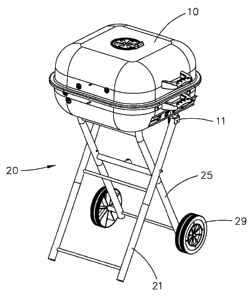
3 Referring to Figs. 1 through 3, there is shown a collapsible barbecue
4 cart according to the preferred embodiment of the present invention. The
barbecue cart includes a stove 10 and a collapsible stand 20. The stove
6 10 will not be described in detail for being conventional.
7 The collapsible stand 20 includes a first pair of legs 21 and a second
8 pair of legs 25. The legs 21 are connected to each other by three
9 crossbars. Each of the legs 21 is pivotally connected to the stove 10 by a
joint 11. Each of the legs 21 is pivotally connected to a related one of the
11 legs 25. The collapsible stand 20 can be moved between an extended
12 position shown in Fig. 4 and a collapsed position such as shown in Fig. 7.
13 The legs 25 are connected to each other by three crossbars of which
14 the uppermost one is represented by "26." An insert 27 is installed on the
crossbar 26. The insert 27 defines a recess 28. A whee129 is connected
16 to each of the legs 25.
17 A bracket 16 includes a first section and a second section extending
18 from the first section at the right angle. The first section of the bracket
16
19 is secured to the bottom of the stove 10. The second section of the
bracket 16 defines an aperture 160.
21 A socket 15 is secured to the first section of the bracket 16. The
22 socket 15 defines an aperture 150. The socket 15 receives the insert 27
23 when the collapsible stand 20 is in the extended position.
24 Referring to Fig. 5, a latch 18 includes a first section and a second
section with a diameter than that of the first section and that of the
26 aperture 160. The first section of the latch 18 is inserted through the
27 aperture 160. A ring 17 is connected to the first section of the latch 18
so
28 that the latch 18 is retained on the second section of the bracket 16. An
29 elastic element 19 is installed on the first section of the latch 18. The
3
CA 02548621 2006-05-26
1 elastic element 19 is compressed between the second section of the
2 bracket 16 and the second section of the latch 18. Biased by the elastic
3 element 19, the second section of the latch 18 is retained in the aperture
4 150 and the recess 28. The insert 27 is retained in the socket 15 so that
the collapsible stand 20 is firmly retained in the extended position shown
6 in Fig. 4.
7 Referring to Fig. 6, the ring 17 is pulled, and the second section of
8 the latch 18 is removed from the recess 28. The insert 27 is removed
9 from the socket 15. Therefore, the collapsible stand 20 can be changed to
the collapsed position shown in Fig. 7.
11 Referring to Fig. 8, the collapsible cart is in the collapsed position. A
12 user holds one of the crossbars between the legs 21 while leaving the
13 wheels 29 rolling on the ground. Thus, the user can easily carry the
14 collapsible cart in the collapsed position.
The present invention has been described through the illustration of
16 the preferred embodiment. Those skilled in the art can derive variations
17 from the preferred embodiment without departing from the scope of the
18 present invention. Therefore, the preferred embodiment shall not limit
19 the scope of the present invention defined in the claims.
4