Note: Descriptions are shown in the official language in which they were submitted.
CA 02548744 2013-03-25
FLASHLIGHT WITH RECHARGEABLE LITHIUM-ION BATTERY
Background
[0001] Rechargeable flashlights are known in which a flashlight containing a
rechargeable battery is provided with a compatible charging unit which both
holds the
flashlight and charges the battery when the flashlight is positioned therein.
As described
in US Pat. No. 5,432,689, it is desirable to provide such a flashlight and
charger
assembly wherein the body of the flashlight is not used as a conduction path
for either
side of a lamp circuit, so that mating parts of the flashlight may be provided
with an
anodized, enamel, or other finish, and do not require re-machining in order to
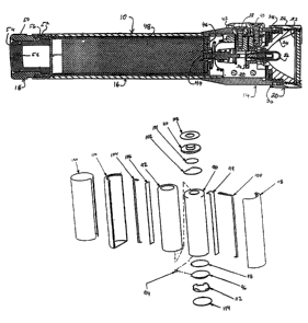
provide
a conductive path between finished mating parts.
100021 In the use of flashlights by armed personnel, such as by policemen, it
is desirable
to provide a flashlight that can be gripped and intermittently actuated with a
single band.
For example, it is desirable to provide an actuator at the rear end of such a
flashlight, so
that the flashlight may be gripped with the fingers of one hand, and the
actuator can be
operated by the thumb of the same hand. However,locating a switch mechanism at
the
rear end of the flashlight while maintaining a construction which does not
utilize the
body of the flashlight as a conducting member, and in which a continuous
connection
is maintained between the battery terminals and a pair of external charging
contacts
presents design difficulties for which no solution \is suggested in the above-
referenced
US Pat. No. 5,432,689.
Summary of the Invention
[00031 In accordance with one aspect of the present invention, a rechargeable
flashlight
is provided in which a the flashlight is charged by two charging contacts
located on or
near the forward end of the flashlight. The flashlight is configured to
provide
intermittent single-handed operation of the lamp circuit, and optionally to
provide
continuous switched operation. Continuous electrical contact between
respective battery
terminals located at the forward end of a battery assembly, and a pair of
external
charging contacts, is maintained by a configuration of springs mounted to a
connection
member located in the forward end of the flashlight. The connection springs
extend
-1-
CA 02548744 2013-10-22
rearwardly from the connection module to maintain contact with the battery
terminals,
while also urging the battery assembly rearwardly within the flashlight. A
spring
loaded plunger located in the connection module is also biased rearwardly, and
aligned
with a terminal of the battery assembly and with an electrical contact on a
lamp base.
The tail of the flashlight includes a slide member, having an actuation
surface at the
rear of the flashlight, for urging the battery assembly in the forward
direction within the
flashlight barrel, and further urging the plunger toward the lamp base
contact.
Hence, intermittent operation of the lamp is provided. In a preferred
embodiment,
continuous operation of the lamp is provided by configuring the tail assembly
to hold
the slide member at a forwardly-advanced position in the rear of the barrel.
[0003a] Accordingly, in one aspect there is provided a rechargeable
flashlight,
comprising: a flashlight housing having a battery compartment; a light element
adjacent a first end of the flashlight housing; a first charging contact; a
second charging
contact; a switch for controlling operation of the flashlight, wherein the
switch is
adjacent a rearward end of the flashlight housing, remote from the first end
of the
flashlight housing; and a rechargeable lithium-ion battery assembly operable
to store a
charge and configured to be positioned in the battery compartment, wherein the
battery
assembly comprises: a lithium-ion cell; a first battery contact and a second
battery
contact for charging the lithium-ion cell, wherein the first battery contact
is electrically
coupled with the first charging contact and the second battery contact is
electrically
coupled with the second charging contact, and wherein the light element is
electrically
coupled with the first and second battery contacts; a control circuit serially
connected
with the first battery contact, wherein the control circuit is operable to
disconnect the
lithium-ion cell from the light source in response to the charge in the
lithium-ion cell
depleting below a pre-determined lower threshold, and wherein the control
circuit is
operable to disconnect the lithium-ion cell from electrical connection with
the first
charging contact when the lithium-ion cell is connected with a battery charger
and the
charge in the lithium-ion cell reaches a pre-determined upper threshold; a
first
electrical path outside the lithium-ion cell and extending from a rearward end
of the
cell to the first battery contact at a forward end of the cell; and a second
electrical path
outside the lithium-ion cell and extending from the rearward end of the cell
to the
second battery contact at the forward end of the cell, wherein the first and
second
electrical paths are separate from the flashlight housing.
-2-
CA 02548744 2013-10-22
[0003b] According to another aspect there is provided a battery assembly
for a
rechargeable flashlight comprising a flashlight housing having a battery
compartment,
a light element adjacent a first end of the flashlight housing, first and
second charging
contacts and a switch for controlling operation of the flashlight, wherein the
switch is
positioned adjacent a rearward end of the housing, remote from the first end
of the
housing, wherein the battery assembly comprises a rechargeable lithium-ion
cell
operable to store a charge, wherein the cell has a first contact and a second
contact,
wherein the first contact of the cell is configured to be electrically coupled
with the first
charging contact and the second contact of the cell is configured to be
electrically
coupled with the second charging contact, and wherein the first and second
contacts of
the cell are configured to be electrically coupled with the light element; a
control circuit
serially connected with the first cell contact, wherein the control circuit is
operable to
disconnect the lithium-ion cell from the light element in response to the
charge in the
lithium-ion battery depleting below a pre-determined lower threshold, and
wherein the
control circuit is operable to disconnect the lithium-ion cell from electrical
connection
with the first charging contact when the lithium-ion cell is connected with a
battery
charger and the charge in the lithium-ion cell reaches a pre-determined upper
threshold; a first conductor outside the lithium-ion cell extending from a
rearward end
of the cell to the first contact at a forward end of the cell; and a second
conductor
outside the lithium-ion cell and extending from the rearward end of the cell
to the
second contact at the forward end of the cell; wherein the first conductor is
connected
with the control circuit and the second conductor is insulated from the first
conductor.
-2a-
CA 02548744 2013-03-25
. .
Brief Description of the Drawings
100041 The foregoing Summary, as well as the following Detailed
Description,
will be best understood in connection with the attached drawings in which:
[0005] Fig. 1 is a perspective view of a flashlight and charger
in accordance with
the present invention.
[0006] Fig. 2 is a perspective view of the flashlight of Fig. 1
removed from the
charger.
[0007] Fig. 3 is a cross-sectional view of the flashlight of
the invention.
100081 Fig. 4 is an exploded view of a connection module
located within the head
of the flashlight of Fig. 3.
[0009] Fig. 5 is a cross-sectional view of the connection
module of Fig. 4.; and
[0010] Fig. 6 is an exploded view of a battery assembly
utilized in the flashlight of
Fig. 3.
Detailed Description of the Drawings
100111 Referring now to FIG. 1, the flashlight 10 is shown
engaged within a
charger 12. The charger 12 is substantially identical in construction with the
charger
shown in US Pat. No. 5,432,689. Referring to FIG. 2, the flashlight 10
comprises a
head assembly 14 connected with the forward end of a barrel 16. A tail
assembly 18 is
-2b-
CA 02548744 2013-10-22
connected with the rear end of the barrel. A guide plate 13 is positioned on
the
exterior of the head assembly 14 for guiding the flashlight into the charger.
Positioned within the guide plate are a pair of charging contacts 40 and 38,
for mating
with compatible connecting contacts located in the charger.
[0012] The forward end of the flashlight is formed by a facecap
assembly 20
which is rotatably mounted at the forward portion of the head assembly 14.
Referring
now to Fig. 3, the facecap assembly 20 holds a circular lens 22 and a
reflector 24
within a cylindrical carrier 26. The terminal rear portion of the reflector
has threads
28 formed thereon to provide a threaded connection with a forward portion of
the head
assembly 14. The outer surface of the facecap assembly 20 is preferably
knurled to
provide a gripping surface thereon, so that the facecap assembly 20 can be
rotated to
move the facecap assembly 20 in the forward OF reverse directions upon the
threads 28
to vary the focus of the flashlight. An o-ring is positioned within a chase 30
formed
about the outer surface of the forward end ofthe head assembly 14 to provide a
fluid
seal between the head assembly 14 and the facecap assembly 20.
[00131 A connection module 32 is positioned within the head
assembly 14.
Described in greater detail hereinbelow, the connection module 32 supports a
lamp
holder 34, in which a bi-pin lamp 36 may be inserted as shown. The connection
module 32 provides continuous electrical connection between battery terminals
44 and
46 and respective ones of a pair of contact screws 38 and 40, which extend
from the
exterior surface of the flashlight 10 through a charger alignment plate 42 and
into the
connection module 32 positioned in the interior of the head assembly 14. The
connection module further provides a switchable electrical connection between
the
battery terminals 44 and 46 and respective terminals of the bi-pin lamp 36.
[0014] The rear portion of the head assembly 14 is press-fit for
permanent
engagement onto the forward end of the barrel 16. A battery assembly 48 is
housed
within the barrel 16. As described further hereinbelow, the battery assembly
has
respective negative and positive contacts 44 and 46 both positioned at the
forward end
thereof within the barrel 16.
-3-
.
CA 02548744 2013-10-22
[0015] A tail assembly 18 is connected with the rear of the barrel 16. The
tail
assembly comprises a cylindrical tail housing 50 having threads 52 formed
about the
exterior forward end thereof to provide a threaded connection with the
interior rear
portion of the barrel 16. A cylindrical slide member 54 is slidably positioned
within
the tail assembly 18. The forward end of the slide member 54 is enlarged so
that the
slide member is captured against rearward movement by an reduced diameter rim
56
formed in the tail housing 50. The slide member 54 is preferably hollow to
provide
storage space for a spare lamp (not shown), and is closed at the rear end
thereof. A
semi-permeable filter member 58 is positioned within a hole extending through
the
rear wall of the slide member 54, in order to vent gases from within the
flashlight.
[0016] More views of the connection module 32 are shown in FIG. 4 and FIG. 5.
The connection module 32 comprises two clamshell housing pieces 60 and 62. The
housing pieces 60 and 62 are formed to capture several conductive components
therein as follows. The lamp base 34 fits within a recess formed between the
two
housing pieces 60 and 62. The lamp base is preferably composed of a liquid
crystal
polymer material having relatively high heat resistance to act as a barrier to
heat
generated by the lamp and to provide a heat shield for the connection module.
The
connection module 32 may be made of an acetol polymer material such as DELRIN,
which provides suitable mechanical performance for moving parts situated
therein.
On the rear surface of the lamp base 34, there is provided a conductive
contact
member 64 for the positive terminal of the lamp circuit. Extending from one
side of -
the lamp base 34, and held within a recess formed in the housing pieces, a
negative
contact member 66 extends within the connection module toward the side of the
module. A terminal portion of the contact member is bent upward and has a*
receiving ring formed therein to connect with the negative contact screw 40. A
conical spring 68 is positioned to extend from the rear of the connection
module 32
to connect with the negative terminal of the battery assembly. The conical
spring 68
has a contact arm portion 70 that runs through the connection module to
connect with
the negative contact member 66. When the flashlight is assembled with the
battery
assembly in place, continuous compressive contact is maintained between the
negative terminal at the forward end of the battery assembly and the conical
spring 68,
-4-
CA 02548744 2013-10-22
so that a continuous charging connection is provided between the negative
contact
screw and the negative terminal of the battery assembly.
[0017] A positive contact member 72 has a ring portion for connecting with the
positive contact screw. The positive contact member is positioned in the
connection
module and extends to provide a circular contact ring 74 which is aligned
within the
connection module at a position to the rear of the lamp base 34. A plunger
cavity 76
is formed in the rear of the connection module between the clamshell pieces 60
and 62.
A plunger 78 is slidably captured in the connection module by a rim 80 formed
thereon. A rear portion of the plunger 78 extends out of the rear of the
connection
module. Within the plunger cavity 76, a spring 82 is compressed between the
rim 80
and the rear of the circular contact ring 74. Outside of the plunger cavity,
the rear of
the plunger 78 connects with a spring 84 that extends rearwardly from the
connection
module to connect with the positive terminal of the battery assembly. The
spring 84
is thus maintained in continuous compressive contact with the positive
terminal of the
battery assembly, so that at all times a conductive path is provided between
the
positive terminal of the battery assembly and the positive charging contact on
the
exterior of the flashlight.
[0018] The plunger 78 has a tip portion aligned with the rear of the lamp base
34, and
the positive lamp contact thereon. The plunger is urged rearwardly within the
plunger cavity 76, by the spring 82, so that in a first position, the tip of
the plunger 78
is maintained out of contact with the positive lamp contact. Referring again
to FIG. 3,
it can be seen that by depressing the slide member 54 into the rear of the
tail assembly,
the slide member 54 urges the battery assembly forward within the barrel 16.
Thus,
when the slide member 54 is so depressed, the movement of the battery assembly
compresses both springs 84 and 82, to urge the tip of the plunger into contact
with the
= positive lamp contact on the rear of the lamp base. The lamp may
therefore be
intermittently switched on and off by holding the flashlight in the fingers of
one hand,
and depressing the slide member with the thumb of the same hand.
[0019] To maintain the lamp in a continuous "on" condition, the tail housing
50 may
be rotated into the rear of the barrel on the threads 52, so that the springs
84 and
82 are again compressed to move the plunger tip into contact with the positive
lamp
-5-
CA 02548744 2013-10-22
contact. Thus, the configuration herein described provides intermittent or
continuous
switching of the lamp.
[0020] The battery assembly is shown in an exploded view in FIG. 6. The
preferred
cell for the battery assembly is a Lithium-ion rechargeable cell. The battery
assembly
provides two battery terminals 108 and 101 exposed at the forward end thereof
in a
concentric arrangement as viewed from the forward end. The use of Li-ion cells
in
consumer products generally requires the use of a battery protection circuit
in series
therewith, due to the high energy density and potential volatility of Li-ion
cells. The
battery protection circuit disconnects the Li-ion cell from the lamp circuit
from further
charging when the cell is fully charged, and also disconnects the cell from
the lamp
circuit when the charge is depleted below a predetermined threshold. The
battery
assembly is constructed as follows. A Li-ion rechargeable cell 90 is first
provided
with a shrink-wrap insulating jacket 92. A conductive strap 94 is connected
with the
cell contact at the negative end of the cell and with a protection circuit
board 96. An
insulating spacer 98 is positioned between the rear of the cell 90 and the
forward side
of the circuit board 96. A length of insulating tape 99 is applied to one side
of the
jacket 92, and a conductive strap 100 is connected with the circuit board 96
at the rear
of the battery assembly, and extends to the forward end of the assembly for
connection
to the positive cell contact at the forward end. The forward end of the strap
100
extends across the positive cell contact, and then connects with a positive
battery
contact terminal member 101. The strap 100 is bent backwards, and an
insulating
spacer 102 is positioned between the positive contact of the cell and the
positive
contact terminal member.
[0021] On the other side of the jacket 92, another strap 104 is connected to
the
negative cell contact, and is positioned over an insulating strip 106
positioned on that
side of the jacket. The forward end of the strap 104 is connected to an
annular
negative battery contact terminal 108 at the forward end of the cell. The
annular
negative terminal 108 is positioned on an insulating member 110 which has a
hollow
cylindrical vertical extension formed therein for guiding the spring into
contact with
the positive contact terminal 101.
-6-
CA 02548744 2006-06-08
WO 2005/060715
PCT/US2004/043286
[0022] A disk-shaped low-profile housing 112 is placed over the rear side of
the
protection circuit, and an insulating spacer 114 is placed on the rear side of
the
housing, to mechanically protect the protection circuit. Finally, the sheathed
cell,
strap, and protection circuit arrangement is enclosed in a rigid plastic shell
formed by
shell members 116 and 118. The shell is closed at the rear end, and is open at
the
forward end to permit the springs to connect with the respective contacts. An
adhesive label 120 may be placed over the shell to hold the shell members
together.
[0023] The terms used here and above are intended by way of exemplary
description,
and not of limitation. There is no intent for such terms of description to
otherwise
limit the scope of the appended claims.
-7-