Note: Descriptions are shown in the official language in which they were submitted.
CA 02549013 2006-06-12
WO 2005/062970 PCT/US2004/043505
LIFT VAN SYSTEM
BACKGROUND OF THE INVENTION
1. Technical Field
[0001] The present invention relates generally to packaging and containers,
and relates more
specifically to a corrugated fiberboard lift van system.
2. Related Art
[0002] Lift vans are widely utilized in the moving and transportation
industries as containers
for storage, packaging, and transport. Lift vans provide a relatively large
uniform sized
container in which items can be easily stored and moved. Typical dimensions
are, e.g., 88"
in length x 45" in width x 88" in height. Because of their uniform dimensions,
the containers
can be easily placed on pallets (or incorporate a pallet) that allow the
container to be moved
with a forklift.
[0003] Most prior art lift vans are constructed from plywood. Accordingly,
constructing,
packaging and moving the lift vans involve costly operations. Also, some
countries are
beginning to place restrictions on the import of plywood due to environmental
issues
involving bugs and the like infesting the wood.
[0004] One solution to the problem involves utilizing cardboard or fiberboard
instead of
plywood. Unfortunately, significant complexity is introduced in designing a
cardboard/fiberboard lift van due to the fact that the container must provide
significant
structural resiliency. To address this, prior art cardboard lift vans require
many different
cardboard/fiberboard parts that are expensive and complicated to manufacture.
Assembly of
the prior art designs is also complicated given the many parts involved in
constructing such a
NORA-0003PCT 1
CA 02549013 2006-06-12
WO 2005/062970 PCT/US2004/043505
large containment device. In addition, the cardboard/fiberboard lift van must
be collapsible
so that it can be broken down for storage when not in use. Accordingly, a need
exists for a
simple to manufacture and assemble lift van system.
SUMMARY OF THE INVENTION
[0005] The present invention addresses the above-mentioned problem, as well as
others, by
providing a lift van container that can manufactured from a small number of
parts, and be
easily collapsed or erected as needed.
[0006] In a first aspect, the invention provides a lift van system that
includes: a top and
bottom cap, each comprising a folded sheet, wherein each folded sheet has
substantially
similar design specifications; first and second side wall sections, each
comprising a single
sheet, wherein the first and second side wall sections have substantially
similar design
specifications; and a pallet, wherein the pallet sits within the bottom cap.
[0007] In a second aspect, the invention provides a lift van container,
comprising: a top and
bottom cap, each comprising a folded sheet of material, wherein both folded
sheets have
substantially similar design specifications; first and second side wall
sections, each
comprising a foldable sheet of material, wherein the first and second side
wall sections have
substantially similar design specifications; and a pallet, wherein the pallet
can be snapped
into a lip of the bottom cap.
[0008] In a third aspect, the invention provides a container, comprising: a
top and bottom
cap, each comprising a folded sheet of material, wherein both folded sheets
have substantially
similar design specifications; and first and second side wall sections, each
comprising a
foldable sheet of material that forms three walls when erected, wherein the
first and second
side wall sections have substantially similar design specifications.
NORA-0003PCT 2
CA 02549013 2009-11-04
In accordance with an aspect of the present invention, there is provided a
lift van
system that includes:
a top and bottom cap, each comprising a folded sheet, wherein each folded
sheet
has substantially similar design specifications allowing interchangeability
therebetween;
first and second side wall sections, each comprising a single sheet, wherein
the
first and second side wall sections have substantially similar design
specifications
allowing interchangeability therebetween; and
a pallet, wherein the pallet sits within the bottom cap;
wherein the top and bottom caps and sidewall sections further comprise fork
lift
holes.
In accordance with another aspect of the present invention, there is provided
a
lift van container, comprising:
a top and bottom cap, each comprising a folded sheet of material, wherein both
folded sheets have substantially similar design specifications allowing
interchangeability
therebetween, wherein the bottom cap includes a fold down end flap that can be
folded
downward relative to two adjacent side flaps;
first and second side wall sections, each comprising a foldable sheet of
material,
wherein the first and second side wall sections have substantially similar
design
specifications; and
a pallet, wherein the pallet can be secured into the bottom cap.
In accordance with another aspect of the present invention, there is provided
a
container, comprising:
a top and bottom cap, each comprising a folded sheet of material, wherein both
folded sheets have substantially similar design specifications allowing
interchangeability
therebetween; and
first and second side wall sections, each comprising a foldable sheet of
material
that forms three walls when erected, wherein the first and second side wall
sections have
substantially similar design specifications;
wherein the top and bottom caps and sidewall sections further comprise fork
lift
holes.
2a
CA 02549013 2006-06-12
WO 2005/062970 PCT/US2004/043505
BRIEF DESCRIPTION OF THE DRAWINGS
[0009] Figure 1 depicts an isometric view of a lift van container in a
collapsed position in
accordance with the present invention.
[0010] Figure 2 depicts an isometric view of a bottom of the lift van
container of Figure 1
with the pallet being installed.
[0011] Figure 3 depicts an isometric view of a bottom of the lift van
container of Figure 1
with a first part of a sidewall installed and an end flap folded down for
loading.
[0012] Figure 4 depicts an isometric view of an erected lift van system in an
erected position
in accordance with the present invention.
[0013] Figure 5 is design schematic of a top and bottom cap.
[0014] Figure 6 is a design schematic of a sidewall part.
[0015] Figure 7 is a design schematic of a pallet design.
[0016] Figure 8 is a side view of the design schematic of Figure 7.
[0017] Figure 9 is an alternative design schematic of a top and bottom cap.
[0018] Figure 10 is a top cross-sectional view of the sidewall sections of the
container.
DETAILED DESCRIPTION OF THE INVENTION
[0019] Figure 1 depicts an isometric view of a lift van container 10
("container 10") in a
broken down or collapsed position, suitable for storage and transport before
being erected and
loaded with wares. Figure 4, described below, depicts the container 10 in its
erected position,
suitable for holding wares. In the collapsed position, container 10 is
completely packaged
within a top cap 12 and a bottom cap 14. Enclosed with the top cap 12 and
bottom cap 14
are a pallet 20 (described below) and side wall sections 30, 40 (also
described below).
[0020] Both of the top and bottom caps 12 and 14 are identical in that they
are created from
the same (or substantially the same) dye / design specifications, i.e., they
are produced from
NORA-0003PCT 3
CA 02549013 2006-06-12
WO 2005/062970 PCT/US2004/043505
identical (or substantially identical) cut sheets, e.g., cardboard,
fiberboard, etc. Figure 5,
described below, depicts a design schematic of the top and bottom cap 12, 14.
Figure 9
depicts an alternative embodiment of a top and bottom cap. Because the top and
bottom
share the same specifications, the complexity of the manufacturing process is
greatly reduced.
[0021] As shown in Figure 1, both the top and bottom caps 12, 14 have
interlocking tabs 16
that allow the container 10 to be securely packaged in the collapsed position.
In particular,
each of the top and bottom caps 12, 14 has a first side flap 17 with two
exterior tabs and one
interior tab, and a second side flap 19 with one exterior tab and two interior
tabs (the tab
features are described in further detail in Figure 5). When a first side flap
17 of the bottom
cap 14 is mated with a second side flap 19 of the top cap 12 as shown, the
exterior tabs
interlock with the interior tabs, thereby securing the top cap 12 to the
bottom cap 14. The
alterative embodiment shown in Figure 9 does not include interlocking tabs 16.
[0022] Each cap also includes a plurality of forklift holes 18 that allow the
container 10 to be
lifted and moved from any of the four sides with a standard forklift. The
forklift holes 18 are
accessible in both the collapsed and erected positions.
[0023] Figure 2 depicts an isometric view of the bottom cap 14 of the lift van
container 10
with a pallet 20 being installed. Pallet 20 is comprised of a pallet surface
22, a plurality of
bocks 24, and a bottom floor 26. Defined within the entire inside bottom edge
of the bottom
cap 14 is a lip 28 for receiving the bottom floor 26. The bottom floor 26 of
the pallet 20 is
sized to fit securely into an edge 28 of the bottom cap, and thus, obviate the
need for any
additional parts to secure the pallet. It should be noted any system for
receiving and securing
pallet 20 in bottom cap 14 could be utilized. Figure 7, described below,
depicts a design
schematic of the pallet 20.
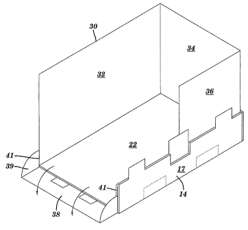
[0024] Figure 3 depicts an isometric view of the container 10 with a first
sidewall section 30
installed. First sidewall section 30 includes three segments 32, 34, and 36
that form two full
NORA-0003PCT 4
CA 02549013 2006-06-12
WO 2005/062970 PCT/US2004/043505
walls (segments 32 and 34) and a partial wall (segment 36). A second sidewall
section 40
(not shown), of the same design specifications as the first sidewall section
30 is placed
opposite the first sidewall section 30 and overlaps with segments 32 and 36 to
form the
remain walls of the container. Figure 6, described below, depicts a design
schematic of side
wall sections 30. Figure 10 depicts a cross-sectional top view of both wall
sections 30 and
40.
[00251 As also shown in Figure 3, bottom cap 14 includes a fold down end flap
38 that
allows a first side edge of the bottom cap 14 to be folded down into an open
position for
loading/unloading. Fold down end flap 38 includes rounded edges 39 that pivot
in and out of
folds 41 formed between layers that make up side flaps 17 and 19 (19 not
shown) of the
bottom cap 14. The configuration shown in Figure 3 would be typical for
loading and
unloading the container 10. Once the loading/unloading process is complete,
fold down end
flap 38 can be secured back into folds 41 of the bottom cap 14. Note that no
additional parts
are required to open and/or secure the fold down end flap 38.
[00261 Figure 4 depicts an isometric view of an erected lift van container 10
having both
sidewall sections 30 and 40 installed and the top cap 12 placed thereon. Note
that the
sidewall sections 30, 40 overlap with each other, such that only side wall
section 40 is visible
in the view shown. As noted above, both sidewall sections 30, 40 comprise the
same design
specifications - i.e., they are interchangeable and thus comprise the same (or
substantially the
same) part. Second side wall section 40 includes three segments 42, 44, 46 (46
not visible in
this view). Figure 10 shows a cross-sectional top view of the first and second
side wall
sections 30, 40.
[00271 Referring now to Figure 5, a design schematic of bottom cap 14 ("cap
14") is shown.
(As noted above, top cap 12 is identical to bottom cap 14.) Cap 14 include a
flat surface 50,
opposed side flaps 17 and 19, a fold down end flap 38, and a fixed end flap
52. As described
NORA-0003PCT 5
CA 02549013 2006-06-12
WO 2005/062970 PCT/US2004/043505
above, fold down end flap 38 includes rounded edges 39 that allows fold down
end flap 38 to
be pivoted into and out of folds 41 (formed when side flaps are folded as
described below).
Opposed side flaps 17, 19 each comprise an interior and exterior layer folded
together. In
particular, side flap 17 includes an exterior section 70, an interior section
72, an inner fold
line 74 and an outer "double" fold line 76. Interior section 72 can be folded
inwardly along
the outer "double" fold line 76 to mate with the exterior section 70, both of
which can then be
folded inwardly perpendicular to the surface 50 to form side flap 17. Interior
section 72
includes a plurality of locking tabs 78 that lock into receiving holes 80 to
secure the flap in
position. Side flap 19 is constructed in a similar fashion.
[0028] When constructed, side flaps 17, 19 form folds 41 (shown in Figure 3)
that receive the
rounded edges 39 of the fold down end flap 38 at one end, and fixed edges 86
of the fixed
end flap 52 at the other end.
[0029] As can be seen, interlocking tabs 16 are cut into the side flaps 17,
19. The tabs that
extend from the interior section 72 form interior tabs (e.g., 82), and the
tabs that extend from
the exterior section form exterior tabs (e.g., 84). Fork lift holes 18, as
described above, are
also provided. As noted, Figure 9 depicts an alternative embodiment of a cap
100, which is
substantially similar to that shown in Figure 5, except that it does not
include interlocking
tabs 16.
[0030] Referring now to Figure 6, a schematic diagram of side wall section 30
is shown,
which forms three wall segments 32, 34, and 36, described above in Figure 3.
Side wall
section 30 includes three folds 90, 92 and 94, which allow the side wall
section 30 to be
folded for storage in the collapsed position within top cap 12 and bottom cap
14 (Figure 1).
Folds 92 and 94 are used to fold the wall section 30 when erected (Figures 3
and 4). Fold 92
may be reverse scored, allowing the sidewall section 30 to be folded in both
directions. Side
NORA-0003PCT 6
CA 02549013 2006-06-12
WO 2005/062970 PCT/US2004/043505
wall section 30 also includes fork lift cutouts 68 that match up with the
forklift cutouts 18 in
the bottom cap 14. As noted above, both side wall sections 30 and 40 are
interchangeable.
[0031] Referring now to Figures 7 and 8, pallet 20 is shown, which comprises a
bottom floor
26, a plurality of blocks 24, and a pallet surface 22 (Figure 8). Blocks 24
are spaced to form
openings 92 to provide a four way entry for a fork lift device. Blocks 24 may
be formed from
any type of structure, e.g., corrugated layers, etc. Pallet floor 22 may be
comprised from,
e.g., a two-piece cross laminated / corrugated structure.
[0032] The foregoing description of the preferred embodiments of the invention
has been
presented for purposes of illustration and description. They are not intended
to be exhaustive
or to limit the invention to the precise form disclosed, and obviously many
modifications and
variations are possible in light of the above teachings. Such modifications
and variations that
are apparent to a person skilled in the art are intended to be included within
the scope of this
invention as defined by the accompanying claims.
[0033] It should be appreciated that the invention could be fabricated from
any type of
material, including, but not limited to cardboard, corrugated fiberboard,
boards constructed
from polymers, composites, plastics, foam, etc. Moreover, while the caps 12,
14 (as well as
the side wall sections) are described as being identical, they need not be
exactly the same,
i.e., they could include some differences. However, as noted above, by
maintaining the same
design for both caps and both side wall sections, the manufacturing complexity
and cost is
reduced. In addition, while the embodiments described above are generally
directed toward a
lift van container system, the inventive features could be applied to any type
of container of
any dimension.
NORA-0003PCT 7