Note: Descriptions are shown in the official language in which they were submitted.
CA 02549057 2006-06-12
WO 2005/058717 PCT/AU2004/001776
SOFTWARE AND METHODS FOR AUTOMATED PALLET
INSPECTION AND REPAIR
Field of the Invention
The present invention relates generally to the repair of wooden pallets, and
specifically
to an automated process for scanning pallets and identifying individual
elements of the
pallet for removal, replacement, or repair. It also applies to pallets
constructed from
other materials such as plastic, metal or composites.
Description of Related Art
Commer cial movement of materials typically uses a wooden pallet on which the
material
is placed or secured. This pallet is typically constructed with a flat upper
deck consisting
of planks or boards of timber nailed, screwed, or glued to parallel beams
known as
bearers or stringers. Bottom boards are similarly attached to the bearers. The
framework allows the insertion of the "forks" of a forldift or other machine
to raise and
move the pallet and its load of materials. There are several pallet designs in
use and are
distinguished generally by place of manufacture and use. For example, pallets
made and
used in Australia, New Zealand, the United States, Canada, and Europe are all
of
different designs. In some designs, for example, blocks are used with or in
place of
bearers to separate the top and bottom boards. While timber pallets are the
most
common, pallets of other materials such as plastic, metal, or composite
material are also
in use.
During normal use, the pallets may be dropped, overloaded, crushed or
otherwise
damaged. Damaged pallets are often returned to the pallet provider or other
supplier for
inspection, repair or replacement. The inspection and decision process is
currently done
by dulled human inspectors, or by automated means that implement specific
criteria,
and decide if a pallet is damaged, and if so, decide to repair or discard the
pallet. Using
human inspectors is desirable because they can inspect and immediately repair
each
pallet at a single station. This can be done by presenting each pallet in
turn, for example,
on a conveyor, such that the inspector can see pallet, decide if damaged, and
repair it or
discard it. Human operators, on the other hand, are undesirable because the
inspection
Substitute Sheet
(Rule 26) RO/AU
CA 02549057 2006-06-12
WO 2005/058717 PCT/AU2004/001776
and repair decision is not uniform, as each inspector will naturally implement
repair
based on his or her judgement. It is also undesirable from a safety point of
view as
accidents or injury may occur in such an environment.
Human operators may be replaced by an automated pallet inspection and repair
apparatus. Some current automated systems use stereoscopic pairs of cameras to
collect
pallet geometry and topography information, then use computer programmes to
make a
repair or discard decision by uniformly implementing specific pallet criteria.
This is
done by first determining the pallet's design - e.g. Australian or European -
then
comparing the geometry and topography of the individual pallet against
criteria for the
pallet's design. Current systems, however, decide only to repair or discard
each
inspected pallet, that is, each pallet either does or does not pass the
inspection criteria.
If the pallet passes, it is placed back in service. If it does not pass, it is
sent for repair.
The repair process in current automated systems, however, is similar to the
manual
inspection process above. The pallets needing repair are sent by conveyor,
past one or
more human repair stations where the repairer inspects the pallet, determines
what
needs repair and then repairs it. In some cases, a pallet may be damaged to a
degree
that it is determined to be beyond repair and may be discarded. A process
where the
repairer makes this determination has an additional disadvantage that repairer
may be
inclined to declare a pallet beyond repair, as it is minimises the work to be
done. Even in
the best case, a system with an automated inspection and a human repairer has
some of
the same disadvantages (in uniformity and safety) of the totally human
inspection and
repair process.
What is needed is a process for automatically inspecting a pallet to determine
if it needs
repair. If no repair is needed, the pallet is placed back in service. If
repair is needed, the
pallet is sent to an automated repair station with a list of repairs to be
made. The repair
station receives the pallet and malees the listed repairs. Additionally, a
determination
may be made that the pallet is beyond repair, in which case, the pallet is
sent to the
repair station and is disassembled so that undamaged components may be re-
used.
2
CA 02549057 2006-06-12
WO 2005/058717 PCT/AU2004/001776
BRIEF DESCRIPTION OF THE DRAWINGS
For a more complete understanding of the present invention and for further
advantages
thereof, reference is now made to the following Description of the Preferred
Embodiments taken in conjunction with the accompanying Drawings in which:
Figure i is a schematic top plan view diagram of a pallet;
Figure 2 is a schematic top plan view diagram of an inspection station;
Figur a g illustrates a schematic side elevation of a pallet; and
Figure q. illustrates a logic flow chart of a pallet repair process.
DESCRIPTION OF THE PREFERRED EMBODIMENTS
An automated pallet inspection and repair system and apparatus comprises an
inspection station connected to a computer. A pallet to be inspected is moved
relative to
the inspection head. The pallet may be on a conveyor or moved using a robotic
manipulator or other device. Alternatively, the pallet may be in a stationary
location and
the inspection head may move across it. The sensing head comprises of a set of
at least
one laser and a camera, with the camera recording the reflected laser profile
across a
width of a pallet. Extra cameras can be used to scan wider areas but
stereoscopic camera
pairs are not needed. Resulting information from the sensing head is collected
and
processed by the computer to represent the geometry and topography of the
pallet as a
two-dimensional representation. The representation is analysed so that
individual
elements, (viz., boards, planks, bearers, blocks, etc.) are identified and
located by
coordinates. The pallet design is determined by the number, size, and location
of the
elements. The elements are analysed against specific criteria for the pallet's
determined
design. This includes criteria for the element alone (size, location,
integrity, damage,
missing or raised nails, etc.), inter-elemental criteria (spacing, overlap,
etc.), and pallet
design criteria (missing or superfluous elements, etc.). If the pallet is
determined to
have not passed the criteria, a list of specific repairs is generated. This
list includes
which element is to be repaired and the nature of the repair (remove, replace,
reattach,
3
CA 02549057 2006-06-12
WO 2005/058717 PCT/AU2004/001776
repair, etc.). The data comprising the list of repairs to be made accompanies
the pallet to
a repair station, either physically or logically through the use of a traclang
system. In
preferred embodiments, the repair station is an automated repairer, for
example, a robot
arm using a nail gun, band saw or other saw, prying levers, etc., to implement
the exact
repairs determined necessary. After repair, the pallet is returned to service.
If the pallet
is determined to have passed the criteria, it is returned to service without
stopping at the
repair station. The analysis may also indicate that the pallet is not to be
repaired, but
rather disassembled. In this case, the list of repairs includes only the steps
to
disassemble the elements for re-use, and the parts that are to be reused and
those that
are to be discarded.
In the preferred embodiment, the present invention provides coordinate outputs
sufficient to automate the component repairs, for example through robotic arm
movements, band saw positioning and activation, nail placement, etc.
Figure 1 illustrates one design of a pallet loo. The pallet consists of top
boards 102,
labelled TB o through ~, and corresponding bottom boards labelled BBo through
BB4.
The top boards are supported by three horizontal bearers or stringers
loq.,106, and 108,
labelled Bo, B1 and B2. Other designs will have different numbers of boards,
different
sized boards, and different spacing between boards, and may have different
numbers
and styles of bearers. Blocks and connector boards may be substituted for
bearers in
some designs. In the illustrated design, top board o and top board 7 are wider
than the
other six boards. For the purpose of this invention the pallet can be
considered to be laid
out in an orthogonal x-y-z configuration where the x-axis runs horizontally
(with
reference to Figure 1) across the bottom of the pallet parallel to beam or
bearer 108. The
y-axis runs vertically (with reference to Figure 1) along the left edge of top
board 1. The
z-axis is orthogonal to both x and y.
There are four processes that make up the preferred method of automated pallet
inspection and repair. The first process is data capture. This means capturing
all of the
data about the physical or structural make up of a pallet that is required to
make the
deter minations about the nature, extent and order of the repair process. The
second
process is the analysis of the captured data. The analysis simplifies the data
and relates
4
CA 02549057 2006-06-12
WO 2005/058717 PCT/AU2004/001776
the data to known facts so that a repair process, using certain fixed
processes can be
specified. The third process is generating a list of detailed steps based on
what repair
processes are available and what repairs are needed, as determined by the data
and
analysis of it. The detailed steps necessary to make the repairs on a pallet
is called a
"recipe". The fourth process is to implement the recipe using automated
equipment. In
preferred embodiments, an industrial robot reads a step specified by the
recipe and
implements that according to a flexible programme. Each step is processed in
turn.
One embodiment of the present invention consists of two computer systems and a
mechanical means for moving pallets. These systems may reside on one or more
physical computer processors or hardware, and may be distributed or collected.
The
first computer system is called the capture system, which collects information
about the
geometry and topography of the pallet. The second computer system is called
the
analysis system, which analyses the geometry and topography of the pallet and
determines the pallet design and then using the pallet design specifications
analyses the
pallet and decides whether it is to be repaired or returned to service. It is
not required
that the two computer systems be separate or distinct. The mechanical means
moving
the pallet may be a conveyor belt or chain or a robotic arm or other system
for
transporting the pallet through the inspection head.
Figure 2 illustrates one implementation 200 of the mechanical means for moving
pallets.
This comprises a chain conveyor supporting a pallet 2oq. and moving it in the
direction
of the arrow, left to right. The pallet 2oq. moves under twin lasers 206 and
208. These
lasers illuminate and sensors capture the entire width of the pallet 2oq.. In
some
embodiments there is an overlap in the laser beams in the middle as shown by
210. As
the pallet 2oq. moves under the lasers 206 and 208, information about the
geometry and
topography of a pallet is captured by cameras and sent to the capture computer
system
212. Such laser and sensor systems are well lmown, as are the methods for
using such
lasers to collect this information. The system may be replicated to collect
data on the
other faces of the pallet simultaneously or asynchronously from the top deck.
It will be
obvious that this may also be achieved using a different number of laser and
camera
combinations than the twin set up described above.
5
CA 02549057 2006-06-12
WO 2005/058717 PCT/AU2004/001776
The capture computer system 21a performs the following steps. First it
collects the
profile information of the pallet, that is, it collects the geometry and
topography
information from the lasers and sensors. The sensors return a stream of three-
dimensional coordinates. The cameras/sensors are synchronised so that
overlapping
points illuminated by multiple lasers give the same coordinate values when
viewed from
each sensor or camera. The scans from the two lasers are then combined to give
a set of
coordinates for the entire width of the pallet. This process is repeated for
each profile
scanned as the pallet moves relative to the lasers and cameras
When analysing the top deck, the scanned data is filtered to give only the top
surface
geometry and topography. This is accomplished by discarding any points that
have a z-
coordinate that is below a given threshold or filter line. This removes from
analysis any
point corresponding to a bearer or the bottom of the pallet or the
transporting conveyor
or robotic manipulator, for example. It will be obvious that the same process
could be
applied when analysing any specific face or deck of the pallet. In some
embodiments,
individual planes are established for each bearer. The planes can be combined,
averaged
or used as separate data references.
The laser scans are timed according to the speed of the pallet transport
mechanism so
that scans occur at regular distances along the length of the pallet in the
direction of
movement. Typically, this is set to scan at lmm linear distance, though it
could be at any
chosen resolution distance.
Next, the corner points of the pallet are found using a q.5-degree filter.
This locates the
four points at the extremities of the pallet. That is, it finds the point of
(minimum x
minimum y (minimum x maximum y), (maximum x minimum y), and (maximum x
maximum y). These four points determine the corners of the pallet. These are
typically
referred to as PPo, PP1, PP2, and PPg respectively, where PPo and PP2 lie on
the x-axis,
and PPo and PP1 lie on the y-axis. PPo and PP3 are diagonally, as are PPl and
PP2.
Next, the computer software finds the offsets between the image origin and
pallet origin
to give the x and y offset distances of the pallet. That is, it calculates the
size of the pallet
by subtracting combinations of PPo, PP1, PP2, and PP3. The data is also
normalised by
relocating the coordinates so that PPo lies at the origin of the pallet
coordinate system,
6
CA 02549057 2006-06-12
WO 2005/058717 PCT/AU2004/001776
and PP1 and PP2 lie on the x- and y-axis respectively. A second set of
coordinates, based
around the image datum, is used when calculating automatic repair parameters.
To convert from the three-dimensional topographical information to a two-
dimensional
geometric representation, first the locations and heights of the bearers
(labelled Bo, B1,
B2) are found in the image by inspecting the profiles most likely to represent
bearer
locations. When the bearer heights and locations have been determined, a
series of filter
planes is drawn offset from the bearers (shown as element got in Figure 3).
This can
also be achieved by finding planes best fitting the surface of the boards and
drawing a
filter plane offset below. Each point in the three dimensional representation
is then
checked against the corresponding filter plane. Points above the filter plane
are
identified as belonging to boards, points below belonging to bearers or other
structural
elements. The board points are then further filtered and assembled into arrays
of points
on board edges belonging together. This can be done using any standard edge
finding
technique applied to the set of points above the filter line and an edge chain
following
algorithm. These edge arrays represent boards or parts of boards and are used
in later
analysis. If a two dimensional (geometry only) scanning and inspection head is
used,
electronic means (eg sensor range restrictions) are used to filter the boards
from other
data, with the same array identification and assembly process taking place.
The arrays
do not contain height related data, only 2D geometrical position of points
above the filter
line.
The analysis computer system 21q. performs the steps shown in Table 1.
Step Description
1 The data stream from the inspection head is captured to
construct a pallet
model in computer memory. This process uses the known resolution
of the
inspection head and the known pallet velocity and distance
from the sensing
head to construct a three dimensional topographic model
and subsequently a
two dimensional geometric model of the pallet being analysed.
Pallet corner
oints are calculated from to o ra hical data and stored.
2 Geometric model is broken down to give arrays of points
representing the
ed es of each board (and ed es of artial boards)
7
CA 02549057 2006-06-12
WO 2005/058717 PCT/AU2004/001776
g Board arrays are checked for completeness (i.e. is the
edge a closed loop?)
and consistency (i.e. edges do not cross). Joined boards
are split by applying
a virtual edge along the most probable line of intersection
between the
boards. Where there are multiple arrays along a single
line drawn parallel to
the Y axis and these arrays are all less than a full board
length in the Y
direction and not overlapping or intersecting, they are
classed as a single
(broken) board. Board arrays are then sorted by their minimum
X value, and
their corner oints are identified and stored.
q. By comparing the number, type and location of identified
boards and the
separation distance between pallet corner points with the
range of possible
known pallet geometries, a pallet type can be assigned
to the pallet
undergoing analysis, determined by the closest match against
the database of
specifications. This matching process can be accelerated
if the system need
only expect a single pallet style. A pallet that cannot
be matched to a specific
allet s le is marked as undefined and further anal sis
on it is halted.
Board types can be assigned (e.g. Intermediate, Lead, etc)
to each board
based on its location relative to pallet corner points
and its approximate
width (from board corner points). Boards within a specified
region of the
allet corner oints are resumed to be lead boards.
6 Pallet quality criteria are loaded from the database into
the analysis system
for the particular pallet type determined above. Each board
array can be
checked against the appropriate board criteria for that
board type. Board
checks may include board width, notches or missing material,
jagged edges,
excessive crookedness, or any other criteria. Any board
array that fails these
tests is marked as a board to be removed. Topographic data
for the region
corresponding to the board is also checked for board thickness,
end splitting,
cracks, holes and other three dimensional features, with
failures again being
recorded for removal.
The board arrays are examined against other quality criteria
to determine if
other non-removal board repairs are necessary. An example
would be the
position of the lead boards relative to the pallet corner
points, with any lead
board that is too far from the corner points marked to
be adjusted, unless it
has already been marked for removal. A hierarchy of board
repair decisions
is imposed with the board removal the highest precedence,
board
reali nment next, and an other o eration lowest.
8 Gaps are checlced against gap criteria, such as gap width.
Gaps that are
larger than a board width are checked to see if a board
will allowably fit into
the gap with appropriate resulting gaps on either side
(Fig q.). If a board will
fit, a phantom array is constructed to represent the missing
board, and it is
marked for a board lacement o eration.
g All results are stored in the database. At this point,
all arrays are marked as
either valid boards, or as boards to be removed, ad'usted
or o erated on.
CA 02549057 2006-06-12
WO 2005/058717 PCT/AU2004/001776
to When this system is implemented in an automated pallet
repair situation,
further calculations and data manipulation are required.
These calculations
are specific to each machine in the repair cell, and might
include the location
(X, Y & Z position and angles) required to insert a bandsaw
blade into a
particular gap to perform the removal operation for a board
that has been
marleed for removal. Where this blade does not fit into
the gap, the board is
marleed for removal with a different device.
11 A recipe is generated for the repair cell, with a list
of operations (jobs)
required to be performed to repair the pallet, and the
associated data for each
of these 'obs. These are sorted to ex edite the re air
c cle time
12 In an inspection system designed for sorting or for quality
control purposes
only, steps 1o and 11 are removed, and replaced by further
topographic
analysis of protruding nails and other features.
TAB LE 1
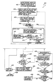
Figure q. illustrates the logic flow for step 8 in Table 1, the process for
examining the
gaps q.oo. The software defines the storage arrays to hold gap values to use
for each of
the profiles q.o2. Each gap is initialised to zero. Starting with the right
hand edge of the
left most board, the gap values are calculated for each board as shown in step
q.oq.. In
step q.o6 the gap values for each board have been stored, so the average gap
can be
calculated. In step q.o8 the average gap is compared against the criteria for
gap based on
the pallet design. If the gap is larger than the design criteria, the gap is
marked as a bad
gap, shown in step q.18 _ In step q.2o, the bad gap is examined to see whether
it is large
enough to fit a new board. If it is large enough to fit in a board, step q.2q.
calculates how
many boards will fit into the gap. That number of boards is then indicated for
the repair
orders. The software then moves to step q.22 to examine the next gap. However,
if the
decision made at step q.2o is that the gap is not wide enough to fit in the
new board and
it still exceeds the criteria for the maximum gap, then step q.28 is
performed. Step q.28
determines which boards must be removed and replaced to fix the gap.
In step q.3o a check is made to see if one of the bounding boards is crooleed.
If the
bounding boards are crooked, the offending board is indicated for removal and
replacement or repositioned, and the resulting gap is re-evaluated q.26. If
none of the
bounding boards are crooked q.3o, then a check is made to see if one of the
boards is
missing any wood (or other material for non-timber pallets) q.32. If one of
the boards is
9
CA 02549057 2006-06-12
WO 2005/058717 PCT/AU2004/001776
missing material, 432, an order is indicated to remove the board and re-
evaluate the
resulting gap in step 426. In step 432, if no boards are missing any material,
then step
434 is performed. A check of the neighbouring gaps is made. If one of the
neighbouring
gaps is smaller than the other then an order is indicated to remove the board
and re-
evaluate the resulting gap step 426. If in step 434 the gaps are equal size
then step 436
is performed, that is, the pallet is marked for manual inspection, or
alternatively a
decision can be made to arbitrarily remove one of the boards.
With reference to step 408, the average gap is compared against the design
criteria, and
if the average gap is acceptable, a test is made to determine if there is a
notch in the
board. Such a notch would give a false indication of a bad gap. The notch test
is shown
in steps 41o through 416. At 410, the gap values across the notch length are
added and
the average calculated. In step 416, the calculated average is compared to the
design
criteria. If the average is greater than the design criteria and the gap is
too big
processing continues to step 418 described above. If at step 416, the average
gap passes
the test against the design criteria that a check is made in step 414 to
determine if there
are more gap values to check. If there are more to check, the step 412 is
performed to
add the next value and then subtract the first value and recalculate the
average.
Processing then continues and step 416. If at step 414 there are no more gap
values to
check, then it has been determined that all gaps values are acceptable and
processing
continues at step 422 to move to the next gap. If there are no more gaps to
test, then
processing ends at step 438.
Returning now to step 426, a repair order indicates the removal of a board or
the
reposition it. Processing then continues at 404 to recalculate the average
gap.
In this way, the pallet is examined board by board and repair orders are
stored for later
use or the pallet is returned to service. If the pallet needs repair, specific
instructions are
determined for removing, replacing, repositioning boards, or to add one or
more boards,
or to remove a protruding nail.
This provides a technical advantage over current automated pallet inspection
and/or
repair systems, which only determine a pass-fail decision for the pallet's
suitability, and
no specific repair instructions are generated. In addition, the technique of
the present
CA 02549057 2006-06-12
WO 2005/058717 PCT/AU2004/001776
invention is sufficient to automate the repair process by connecting the
output of the
process to an automated repair station. Such a station could comprise a robot
arm
which grasps the pallet to be repaired, then, using a band saw and nail gun
and other
devices, removes and replaces specified boards. The instructions to the robot
arm would
be to, for example, "remove the board located between 22.5 cm and q.o cm from
the
leading edge, then nail a new board at 22.o cm from the leading edge."
This same logic may be applied to the inspection of and repositioning of or
replacement
of the bearers, or alternatively to the lower deck of the pallet.
Controlling the robot in an automated repair cell based on the infor mation
generated by
the pallet analysis system described above requires specific robot, PLC and
computer
system linkages or interfaces and software.
Traditional robot control design is relatively simple, based around the
premise that the
robot performs a repeatable job (or series of repeatable jobs) that can be
predefined at
the time the system is designed. Further, traditional robot systems require
human
intervention when there is a problem or a robot crash. To use a robot for
pallet repair, it
must dynamically change its program for each pallet to be repaired, based on
the
particular operations required and the location of the boards or gaps to which
these
operations must be applied. Further, it must automatically recover from
problems and
minor crashes, and flag major crashes to an operator. To achieve this, the
software
system for cell control is broken into three components - these are the robot
controller,
the programmable logic controller (PLC) and the repair recipe generation sub-
system
described in Steps to and 11 of Table 1. The recipe generation sub-system
loads the
necessary robot operations and associated position data into the PLC. This can
be done
in a single batch for a whole pallet, or sequentially as required. In
preferred
embodiments the data is sent as a single batch. Data is checked for
consistency and
completeness, and any missing data is flagged to the recipe generation system.
The robot controller contains a master job and a series of sub jobs that the
master job
can call when required. The master job communicates with the PLC. The PLC
tells the
master job on the robot controller which sub job to call, and sends it the
data that this
sub job will need to run, for example the location and angle of a particular
board to be
11
CA 02549057 2006-06-12
WO 2005/058717 PCT/AU2004/001776
operated on. This data is confirmed by the master job to the PLC, with the
master job
waiting for a handshake from the PLC before continuing. On receipt of the
handshake,
the sub-job is called. The first task in each sub job is to check the robot's
current
location. The position and angle of the pallet gripper must be within a
certain envelope
(which may be a sphere or a cylinder around a predefined point or line known
as the
sub job home position) for the operation to continue. If the robot is within
the allowable
envelope, the sub job continues with the operation. At each step of the
operation, a
handshake is exchanged with the PLC. This handshake allows the PLC to monitor
the
point in the sub job that the robot is up to, which is required for any
automatic recovery
operations. When the sub job is finished (or if an error is encountered)
control of the
robot is passed back to the master job, which communicates with the PLC to get
the next
sub job, and the process continues until the recipe is complete.
Each device in the repair cell is numbered, starting with device o2 and
worlang up to
device 99 (this system could be extended to use any number of digits depending
on the
number of devices in the cell, however two digits are used in preferred
embodiments).
Robot sub jobs that occur at each of these devices are named after the device
where they
occur, eg a two-digit code. The sub jobs that control travel between machines
are named
by combining the names of the two devices between which the robot must move
(eg the
sub job for moving from machine 12 to machine 3q. would be l2gq., whereas to
move
from gq. to 12 would be 3q.12). These numbers are generated by the repair
recipe sub-
system and passed as part of the recipe. The PLC then passes these names in
turn to the
robot master job, which then calls the matching sub job.
Some numbers are reserved for emergency or other recoveries, namely devices oo
and
01. This allows recovery sub jobs to be defined for each device as XXoo and
XXoI where
XX represents the device name. Recovery jobs generally reverse out through the
steps
previously performed at that machine, back to the robot home position for that
device
(eg if sub job o3 runs into trouble, the recovery job would be ogoo or ogol,
depending
on the alarm generated). Depending on the alarm condition, the current recipe
step is
tried again, or the alternatively the recipe is changed dynamically to
overcome the
problem. For example, if the removal of a board to be removed with device o3
fails, and
device oq. is also designed to remove boards, extra steps can be added to the
recipe
12
CA 02549057 2006-06-12
WO 2005/058717 PCT/AU2004/001776
dynamically to take the pallet to device oq. and perform the removal
operation.
Depending on the particular recipe, this action may take place immediately, or
after the
completion of any other pending operations at device o3.
The system relies on the PLC being in ultimate control at all times, and for
handshakes
between the robot and the PLC between any operations, no matter how small. For
safety
purposes, all robot operations must check their start position and confirm
this with the
PLC.
An alternative embodiment of the recipe system would be in a repair cell where
the
pallet is held in a single location and the inspection head and repair devices
are brought
to it. The pallet analysis would proceed as per the earlier description, as
would the
recipe generation. In this style of embodiment, rather than the PLC
instructing the
robot to take the pallet to a particular repair device, the PLC instructs the
robot (or other
manipulator) to bring the repair device to the pallet. The transfer of
position data is
identical to the above description, as are the handshalung and robot location
checking
procedures.
13