Language selection

Search

Patent 2549105 Summary

Third-party information liability

Some of the information on this Web page has been provided by external sources. The Government of Canada is not responsible for the accuracy, reliability or currency of the information supplied by external sources. Users wishing to rely upon this information should consult directly with the source of the information. Content provided by external sources is not subject to official languages, privacy and accessibility requirements.

Claims and Abstract availability

Any discrepancies in the text and image of the Claims and Abstract are due to differing posting times. Text of the Claims and Abstract are posted:

  • At the time the application is open to public inspection;
  • At the time of issue of the patent (grant).
(12) Patent: (11) CA 2549105
(54) English Title: APPARATUS AND METHOD FOR ENHANCED DROPLET COLLECTION IN GAS FLOWS
(54) French Title: APPAREILLAGE ET METHODE DE COLLECTE AMELIOREE DES GOUTTELETTES D'ECOULEMENTS GAZEUX
Status: Granted
Bibliographic Data
(51) International Patent Classification (IPC):
  • B01D 53/26 (2006.01)
  • B01D 53/28 (2006.01)
  • B01D 29/05 (2006.01)
  • B01D 29/56 (2006.01)
(72) Inventors :
  • MACKENZIE, DOUGLAS (Canada)
  • TOEWS, ARNOLD (Canada)
(73) Owners :
  • GAS LIQUIDS ENGINEERING LTD. (Canada)
(71) Applicants :
  • GAS LIQUIDS ENGINEERING LTD. (Canada)
(74) Agent: PARLEE MCLAWS LLP
(74) Associate agent:
(45) Issued: 2013-07-23
(22) Filed Date: 2006-05-31
(41) Open to Public Inspection: 2007-11-30
Examination requested: 2011-04-07
Availability of licence: N/A
(25) Language of filing: English

Patent Cooperation Treaty (PCT): No

(30) Application Priority Data: None

Abstracts

English Abstract

Collection apparatus are installed in a horizontal separator vessel to aid conventional coalescing media to remove mist and droplets from a gas flow, typically downstream from a compressor. The collection apparatus have filaments which act to wick the coalesced droplets either from the conventional coalescing media or from the sides of the vessel toward an annular channel which collects the droplets and assists in delivering the droplets, by gravity, to the bottom of horizontal vessel where they are carried to a collection area. Use of the collection apparatus permits a reduction in the size of the separator vessel and further permits vapor load factors of up to about 10 times that in a conventionally designed separator vessel.


French Abstract

Appareil de collecte installé dans une cuve de séparateur horizontale pour faciliter l'élimination par un milieu de coalescence classique du brouillard et des gouttelettes d'un flux gazeux, typiquement en aval d'un compresseur. L'appareil de collecte comprend des filaments qui agissent pour exercer un effet de mèche sur les gouttelettes regroupées soit depuis le milieu de coalescence classique, soit depuis les côtés de la cuve vers un canal annulaire qui collecte les gouttelettes et facilite l'acheminement des gouttelettes, par gravité, au fond de la cuve horizontale où elles sont transportées jusqu'à une zone de collecte. L'utilisation de l'appareil de collecte permet une réduction en taille du séparateur et permet en outre des facteurs de charge de vapeur allant jusqu'à 10 fois celui d'une cuve de séparateur de conception classique.

Claims

Note: Claims are shown in the official language in which they were submitted.


THE EMBODIMENTS IN WHICH AN EXCLUSIVE PROPERTY
OR PRIVILEGE IS CLAIMED ARE DEFINED AS FOLLOWS:
1. A
collection apparatus for preventing re-entrainment of
droplets coalesced from a horizontal gas flow, the collection apparatus
positioned downstream of one or more thicknesses of coalescing material in a
vessel containing the horizontal gas flow, the coalescing material forming
coalesced droplets in the horizontal gas flow at least some of which flow
along
the inner wall, comprising:
an annular channel positioned adjacent an inner wall of the vessel;
an annular arrangement of a plurality of filaments fluidly connected
to and supported by the annular channel the filaments extending horizontally
upstream therefrom along the vessel's inner wall for engaging the coalesced
droplets flowing along the inner wall and for directing the coalesced droplets
to
the annular channel while permitting passage of the gas flow horizontally
through
the vessel, leaving the coalesced droplets fluidly engaged with the plurality
of
filaments for directing horizontally therealong to the annular channel; and
a port adjacent a bottom of the annular channel for gravity draining
the coalesced droplets from the annular channel.

2. The collection apparatus of claim 1 wherein the plurality of
filaments are supported by the annular channel further comprising:
a layer of a perforated material extending upstream from the
annular channel for sandwiching the plurality of filaments between the layer
of
perforated material and the vessel's inner wall so as to intercept coalesced
droplets flowing along the inner wall while permitting passage of the
horizontal
gas flow therethrough.
3. The collection apparatus of claim 2 wherein the perforated
material is an annular screen.
4. The collection apparatus of claim 1, 2 or 3 wherein the
apparatus is adapted to be positioned between about 45 degrees to about 90
degrees relative to the vessel's inner wall, the port being positioned
downstream
toward a liquid collection area.
5. The collection apparatus of claim 4 wherein the plurality of
filaments are angled relative to the annular channel as necessary so as to be
adapted to be substantially parallel to the inner wall of the vessel.
11

6. The collection apparatus of any one of claims 1 to 5 further
comprising:
a plurality of secondary channels spanning transversely across the
annular channel, the plurality of transverse channels supporting at least the
plurality of filaments therein, the plurality of filaments forming an upstream
face
of tips, the secondary channels being fluidly connected to the annular
channel.
7. The collection apparatus of claim 7 wherein the one or more
thicknesses of coalescing material are one or more demister pads, the
collection
apparatus being adapted to be positioned substantially parallel to a
downstream
face of the demister pads, the upstream face of tips of the plurality of
filaments
substantially directly engaging the downstream face of the demister pads.
8. The collection apparatus of claim 8 wherein the upstream
face of tips of the plurality of filaments substantially engage substantially
all of
the downstream face of the demister pads, the filaments further acting to
concentrate the droplets towards the annular channel.
9. The collection apparatus of any one of claims 1 to 8 wherein
the apparatus is adapted to be positioned in the horizontal gas flow having a
vapor load factor of about 0.5 K to about 5.0 K.
10. The collection apparatus of any one of claims 1 to 9 wherein
the vessel is a lube oil scrubber fluidly connected downstream from a
compressor.
12


11. A system
for removal of mist from a gas flow through a
horizontal vessel comprising:
one or more thicknesses of coalescing material spanning a
diameter of the vessel and spaced downstream from a vessel inlet for
coalescing
droplets thereon, the coalesced droplets thereafter flowing toward an outlet
end
of the vessel at least some of which flow along an inner wall of the vessel;
a liquid collection area adjacent the outlet end of the vessel for
collecting the coalesced droplets therein; and
a first collection apparatus positioned downstream from the one or
more thicknesses of coalescing material for directing the coalesced droplets
to
the liquid collection area, the first collection apparatus having:
an annular channel adapted to be positioned adjacent the
inner wall of the vessel;
an annular arrangement of a plurality of filaments fluidly
connected to and supported by the annular channel, the filaments
extending horizontally upstream therefrom along the vessel's inner wall
for engaging the coalesced droplets flowing along the inner wall and for
directing the coalesced droplets to the annular channel while permitting
passage of the gas flow horizontally through the vessel, leaving the
coalesced droplets fluidly engaged with the plurality of filaments for
directing horizontally therealong to the annular channel; and
a port for gravity draining the coalesced droplets in the
annular channel to the liquid collection area.

13


12. The system of claim 11 wherein the plurality of filaments of
the first collection device are supported by the annular channel and the
coalesced droplets are flowing along the inner wall, further comprising:
a layer of a perforated material extending upstream from the
annular channel for sandwiching the plurality of filaments between the layer
of
perforated material and the vessel's inner wall so as to intercept coalesced
droplets flowing along the inner wall while permitting passage of the
horizontal
gas flow therethrough.
13. The system of claim 12 wherein the perforated material is an
annular screen.
14. The system of any one of claims 11 to 13 wherein the
apparatus is adapted to be positioned between about 45 degrees to about 90
degrees relative to the vessel's inner wall, the port being positioned
downstream
toward a liquid collection area.
15. The system of claim 14 wherein the plurality of filaments are
angled relative to the annular channel as necessary so as to be adapted to be
substantially parallel to the inner wall of the vessel.

14


16. The system of any one of claims 11 to 15 wherein the first
collection device further comprises:
a plurality of secondary channels spanning transversely across the
annular channel, the plurality of transverse channels supporting at least the
plurality of filaments therein, the plurality of filaments forming an upstream
face
of tips, the secondary channels being fluidly connected to the annular
channel.
17. The system of claim 16 wherein the one or more
thicknesses of coalescing material are one or more demister pads, the
collection
apparatus being adapted to be positioned substantially parallel to a
downstream
face of the demister pads, the upstream face of tips of the plurality of
filaments
substantially directly engaging the downstream face of the demister pads.
18. The system of claim 17 wherein the upstream face of tips of
the plurality of filaments substantially engages substantially all of the
downstream face of the demister pads, the filaments further acting to
concentrate the droplets towards the annular channel.


19. The system of any one of claims 11 to 18 further comprising
a second collection apparatus positioned downstream from the one or more
demister pads for directing the coalesced droplets to the collection area, the

second collection apparatus having:
an annular channel adapted to be positioned adjacent an
inner wall of the vessel;
a plurality of filaments fluidly connected to the annular
channel for engaging the coalesced droplets for directing the coalesced
droplets to the annular channel; and
a port for gravity draining the coalesced droplets in the
annular channel to the collection area.
20. The system of claim 19 wherein the first collection device
further comprises:
a plurality of secondary channels spanning transversely across the
annular channel, the plurality of transverse channels supporting at least the
plurality of filaments therein, the secondary channels being fluidly connected
to
the annular channel; and
wherein the plurality of filaments of the second collection device
are supported by the annular channel and the coalesced droplets are flowing
along the inner wall, further comprising:
an inner layer of a perforated material sandwiching the plurality of
filaments between the inner layer and the vessel's inner wall so as intercept
coalesced droplets while permitting passage of the gas flow therethrough.

16


21. The system of claim 20 wherein the one or more
thicknesses of coalescing material are one or more demister pads, the
collection
apparatus being adapted to be positioned substantially parallel to a
downstream
face of the demister pads, the upstream face of tips of the plurality of
filaments
substantially directly engaging the downstream face of the demister pads.
22. The system of claim 19 wherein the plurality of filaments of
the second collection device are supported by the annular channel and the
coalesced droplets are flowing along the inner wall, further comprising:
an inner layer of a perforated material sandwiching the plurality of
filaments between the inner layer and the vessel's inner wall so as intercept
coalesced droplets while permitting passage of the gas flow therethrough.
23. The system of claim 21 wherein the perforated material is an
annular screen
24. The system of any one of claims 11 to 23 further comprising
one or more thicknesses of coalescing material positioned in the vessel inlet
so
as to agglomerate the mist upstream from the one or more thicknesses of
coalescing material in the vessel.
25. The system of any one of claims 11 to 24 wherein the
apparatus is adapted to be positioned in the horizontal gas flow having a
vapor
load factor of about 0.5 K to about 5.0 K.

17


26. Collection apparatus for preventing re-entrainment of
coalesced droplets in a horizontal gas flow, the collection apparatus adapted
to
be positioned downstream of one or more thicknesses of coalescing material in
a
vessel containing the horizontal gas flow, comprising:
an annular channel adapted to be positioned adjacent an inner wall
of the vessel;
a plurality of filaments fluidly connected to the annular channel for
engaging the coalesced droplets for directing the coalesced droplets to the
annular channel;
a plurality of secondary channels spanning transversely across the
annular channel, the plurality of transverse channels supporting at least the
plurality of filaments therein, the plurality of filaments forming an upstream
face
of tips, the secondary channels being fluidly connected to the annular
channel;
and
a port adjacent a bottom of the annular channel for gravity draining
the coalesced droplets from the annular channel.
27. The
collection apparatus of claim 26 wherein the one or
more thicknesses of coalescing material are one or more demister pads, the
collection apparatus being adapted to be positioned substantially parallel to
a
downstream face of the demister pads, the upstream face of tips of the
plurality
of filaments substantially directly engaging the downstream face of the
demister
pads.

18


28. The collection apparatus of claim 27 wherein the upstream
face of tips of the plurality of filaments substantially engage substantially
all of
the downstream face of the demister pads, the filaments further acting to
concentrate the droplets towards the annular channel.
29. The collection apparatus of any one of claims 26 to 28
wherein the apparatus is adapted to be positioned in the horizontal gas flow
having a vapor load factor of about 0.5 K to about 5.0 K.

19

Description

Note: Descriptions are shown in the official language in which they were submitted.


CA 02549105 2013-02-06
1 APPARATUS AND METHOD FOR ENHANCED DROPLET COLLECTION IN
2 GAS FLOWS"
3
4 FIELD OF THE INVENTION
Embodiments of the invention relate to mist eliminators for coalescing
6 fluid
droplets from a vapor stream and more particularly to mist eliminators
7 positioned in a horizontal vapor flow.
8
9 BACKGROUND OF THE INVENTION
It is well known to use coalescing media, such as knitted wire mesh
11 pads and
the like, for mist elimination to coalesce small droplets of fluid which are
12 entrained
in a vapor flow. The coalescing media acts to collect liquid particles on the
13 fibers and
to coalesce the droplets into liquid films and large droplets which can then
14 move
through the coalescing media under the drag force of the gas and downward
by capillary action and gravity through the coalescing media. Typically, the
16 coalesced
collected liquid drains off the downstream face of the coalescing media to
17 a collection zone.
18 It is
known to position a separation vessel downstream of a gas
19 compressor
to remove lubricating oil mists and droplets which have become
entrained in the high pressure flow of gas leaving the compressor.
21 Separation
vessels are typically either vertical or horizontal in
22
orientation. In the case of vertical separation vessels, a gas flow velocity,
as
23 calculated
by the Souders-Brown equation [ V allowable ft/sec :7: K (PL-Pg)/ Pg)1/2],
with a
24 K of about
0.30 to about 0.35 feet/second is typically a maximum velocity to avoid
flooding of mesh pad type coalescing media commonly used. As described in
26 AMISTCO
Technical Bulletin 105, available from AMISTCO Separation Products, Inc., a
1

CA 02549105 2006-05-31
1 calculated
vapor load factor or "K" factor as defined by the Souders-Brown
2 equation
utilizes the K factor for determining the flux cross section area of a mist
3 eliminator
or knockout drum. In the case of horizontal gas flows, the K value may
4 be increased to about 0.5 using conventional mesh pads before flooding
occurs.
lf, in the case of a horizontal gas flow, the gas flow velocity is
6 increased
beyond the typically accepted value of K=0.5, the droplets which
7 collect on
the downstream face of the coalescing media often become re-
8 entrained in
the gas flow negating the separation performed by the coalescing
9 media. Thus,
conventionally large horizontal vessels have been required to keep
the flow velocity below that at which the droplets will not re-entrain in the
gas
11 flow.
12 Thus, there
is a need for apparatus and systems for mist
13 elimination
that minimize the size of the vessel required so as to reduce costs
14 and
environmental impact and increase the efficiency of mist elimination in gas
flows.
16
2

CA 02549105 2006-05-31
1 SUMMARY OF THE INVENTION
2 Collection apparatus according to embodiments disclosed herein
3 permit a reduction in separator vessel size, used to remove mists and
droplets
4 from a gas flow, with velocities and vapor loads exceeding conventional K
values
by up to about 10 times conventional design.
6 In a broad aspect, collection apparatus for the prevention of re-
7 entrainment of coalesced droplets in a horizontal gas flow adapted to be
8 positioned downstream of one or more thicknesses of coalescing material
in a
9 vessel containing the horizontal gas flow, comprises: an annular channel
adapted to be positioned adjacent an inner wall of the vessel; a plurality of
11 filaments fluidly connected to the annular channel for engaging the
coalesced
12 droplets for directing the coalesced droplets to the annular channel;
and a port
13 adjacent a bottom of the annular channel for gravity draining the
coalesced
14 droplets in the annular channel to a liquid collection area.
A first embodiment of the collection apparatus further comprises a
16 plurality of secondary channels spanning transversely across and
intersecting
17 with the annular channel, the plurality of transverse channels
supporting at least
18 the plurality of filaments therein, the secondary channels being fluidly
connected
19 to the annular channel. The first embodiment is designed to be mounted
adjacent a downstream face of a conventional coalescing media, such as a
21 demister pad. The filaments substantially contact the demister pad's
downstream
22 face or the coalesced droplets adhering thereto and act to wick the
coalesced
23 droplets into the annular channel for gravity drainage to the inner wall
of the
24 vessel where they are carried by the boundary flow to the collection
area.
3

CA 02549105 2006-05-31
1 In a second embodiment of the collection apparatus the plurality of
2 filaments are supported by the annular channel and further comprises: an
inner
3 layer of a perforated material sandwiching the plurality of filaments
between the
4 inner layer and the vessel's inner wall so as to permit passage of the
gas flow
therethrough and leaving the intercepted coalesced droplets fluidly engaged
with
6 the plurality of filaments for directing to the annular channel.
7 In another embodiment, the first and second embodiments are
8 employed in series.
9 Preferably, the perforated material is a screen. Further, the
second
embodiment is preferably mounted in the vessel adjacent the collection area,
the
11 port extending adjacent to or into the collection area for discharge of
the
12 collected coalesced droplets therein. The collection apparatus is
mounted
13 between about 45 degrees and 90 degrees relative to the inner wall of
the
14 vessel, the port being located at a leading bottom edge of the
collection
apparatus extending toward the collection area.
16
4

CA 02549105 2006-05-31
1 BRIEF DESCRIPTION OF THE DRAWINGS
2 Figure 1 is a longitudinal sectional view of a lube oil scrubber
3 vessel having a collection apparatus according to an embodiment of the
4 invention installed therein;
Figure 2 is a longitudinal sectional view of a lube oil scrubber
6 vessel having a collection apparatus according to another embodiment of
the
7 invention installed therein;
8 Figure 3 is a longitudinal sectional view of a lube oil scrubber
9 vessel having a collection apparatus according to Fig. 2 installed
therein at a 45
degree angle relative to an inner wall of the vessel;
11 Figure 4 is a longitudinal sectional view of a lube oil scrubber
12 vessel having collection apparatus according to both Figs 1 and 3
installed
13 therein, the collection apparatus being spaced from one another along a
length
14 of the vessel;
Figure 5 is top perspective view of the collection apparatus of Fig.
16 1;
17 Figure 6 is a bottom perspective view of the collection apparatus
of
18 Fig. 1; and
19 Figure 7 is a perspective view of the collection apparatus of Fig.
3.
5

CA 02549105 2006-05-31
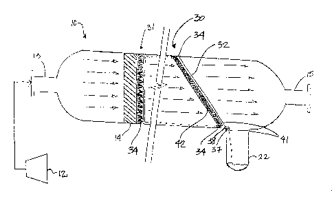
1 DETAILED DESCRIPTION OF THE PREFERRED EMBODIMENTS
2 Having
reference to Figs. 1-4, a horizontal separation vessel 10,
3 typically known as a lube oil scrubber, is connected downstream from a
4 compressor
12 and receives a high pressure, high velocity gas flow G therefrom
at an inlet 13 which contains entrained droplets and mists of lubricating oils
and
6 other such fluids used in the compressor 12, such as for lubrication.
7 Conventional
coalescing media or one or more demister pads 14 are positioned
8 across a
diameter of the vessel 10 to trap the entrained droplets and mist and
9 cause the
droplet size to increase such that the droplets become larger and
heavier and are separated from the gas flow which exits the vessel 10 at an
11 outlet 15.
Typically, the coalesced droplets 16 move diagonally by gravity toward
12 a bottom 18
of an inner wall 20 of the vessel 10 and flow therealong in the
13 boundary
flow of the gas flow G to a collection area 22. Coalesced droplets 16
14 which do not
move to the bottom wall 18 are carried along the inner wall 20 of
the vessel 10 and may gradually move downward due to gravity or the droplets
16 16 are at risk to be re-entrained in the high velocity gas flow G in the
vessel 10.
17 Collection
apparatus 30 are installed in the vessel 10 downstream
18 from the
demister pads 14 to collect the coalesced droplets 16 which are moving
19 along the
inner wall 20 of the vessel 10 and are directed through the collection
apparatus toward the collection area 22.
21 As shown in
Figs. 1, 5 and 6, a first embodiment of the collection
22 apparatus 30
comprises a transverse collector 31 having an annular channel 32
23 which is
positioned adjacent the inner wall 20 of the vessel 10. A plurality of
24 secondary
channels 33 span across and intersect with the annular channel 32 to
which the secondary channels 33 are fluidly connected. A plurality of
filaments
6

CA 02549105 2006-05-31
1 34, typically wire filaments, are supported in the secondary channels 33
and
2 extend outward therefrom away from the secondary channels 33 and the
annular
3 channel 32 to form an upstream face 39 of tips 36 of the filaments 34. The
4 collection apparatus 31 is positioned adjacent a downstream face 35 of the
demister pads 14 such that the upstream face 39 formed by the tips 36
6 substantially contacts the downstream face 35 of the demister pad 14 to
receive
7 coalesced droplets 16 collected thereon or contacts the coalesced droplets
16
8 only for receiving the coalesced droplets 16. The filaments 34 act to wick
the
9 coalesced droplets 16 from the downstream face 35 and direct the droplets
along the filaments 34 to the secondary channels 33 and to the annular channel
11 32. A drainage port 37 is provided at a bottom 38 of the annular channel
32 so
12 as to discharge the droplets along the bottom wall 18 of the vessel 10
where the
13 droplets 16 are carried by the lower velocity boundary layer of the gas
flow G to
14 the collection area 22.
Preferably, the filaments 34 are retained in the secondary channels
16 33 such that the tips 36 of the filaments 34 are splayed outwards
upstream so as
17 to form the upstream face 39 of tips 36 to cover substantially the
entire of the
18 downstream face 35. The filaments 34 become more densely concentrated as
19 the filaments 34 enter the secondary channels 33. The filaments 34 can
form a
conical shape with an apex at the secondary channels 33.
21 Having reference to Figs. 2, 3 and 7 and in a second embodiment
22 of the collection apparatus 30, an annular collector 41 comprises the
annular
23 channel 32 and the drainage port 37 at the bottom 38 of the annular
channel 32.
24 A plurality of filaments 34 are retained in the annular channel and
extend
upstream therefrom in a direction opposite to the direction of the drainage
port
7

CA 02549105 2006-05-31
1 37. A
perforated material 42, such as an annular screen, is also retained in the
2 annular
channel 32 and sandwiches the filaments 34 against the inner wall 20 of
3 the vessel
10. Coalesced droplets 16, which are carried along the inner wall 20,
4 contact the filaments 34 while the gas flow G is permitted to continue to
pass
through the to return to the main gas flow. Should pooling of the coalesced
6 droplets 16 occur in the annular channel 32, the gas flow G exits the
annular
7 channel 32 without becoming re-entrained in the gas flow G.
8 The annular
collector 41 can be mounted in the vessel 10 at a 90
9 degree angle
relative to the inner wall 20 (Fig. 2) or can be mounted at an angle
between about 45 degrees and 90 degrees relative to the wall. If the
collection
11 apparatus is
designed to be mounted at an angle other than 90 degrees (Fig. 3),
12 the
filaments 34 and are angled so as to be parallel to the inner wall 20 when
13 installed.
14 Preferably,
the filaments 34 extend slightly beyond the annular ring
32 and the screen 41, typically about % inch.
16 Preferably,
the annular collector 41 is mounted having the drainage
17 port 37
adjacent or extending into the collection area 22 so as to discharge the
18 collected coalesced droplets 16 to the collection area 22.
19 In use, the
separation vessel 10 typically has one or more
conventional coalescing media, preferably demister pads 14, positioned
21 downstream
from the inlet 13 and preferably at about one diameter distance
22 from the
inlet 13. The inlet 13 may or may not have agglomerators (not shown)
23 installed
therein for providing an initial coalescing of mist to somewhat larger
24 droplets.
One or more collection apparatus 30 according to the embodiments
8

CA 02549105 2006-05-31
1 disclosed
herein may be installed downstream from the conventional demister
2 pads 14.
3 As shown in
Fig. 1, a transverse collector 31 of the collection
4 apparatus
30, according to the first embodiment, is shown installed at the
downstream face 35 of the demister pad 14.
6 As shown in
Figs. 2 and 3, an annular collector 41 of the collection
7 apparatus 30
according to the second embodiment disclosed herein is installed
8 adjacent the
collection area 22, the drainage port 37 preferably extending
9 therein. The
collection apparatus 40 is preferably installed at about a 45 degrees
angle relative to the inner wall 20. In a preferred embodiment the collection
11 apparatus 41
is located at about 5 diameters distance from the inlet 13 of the
12 vessel 10.
13 As shown in
Fig. 4, a first transverse collector 31 according to the
14 first
embodiment is installed at the downstream face 35 of the demister pad 14
and a second collection apparatus 30, an annular collector 41, is installed
16 adjacent the
collection area 22 with the drainage port 37 preferably extending
17 therein.
18 Use of one
or more of the collection apparatus 30 disclosed herein
19 permits K
values, which represent the vapor load factor, to be in the range of 0.5
to about 5.0, which is up to about 10 times that in a conventional separator.
21 Further,
this permits use of separators which are approximately 1/3 the diameter
22 of
conventional vessels, thus decreasing the amount of materials required to
23 build the vessels and the cost associated therewith.
9

Representative Drawing
A single figure which represents the drawing illustrating the invention.
Administrative Status

For a clearer understanding of the status of the application/patent presented on this page, the site Disclaimer , as well as the definitions for Patent , Administrative Status , Maintenance Fee  and Payment History  should be consulted.

Administrative Status

Title Date
Forecasted Issue Date 2013-07-23
(22) Filed 2006-05-31
(41) Open to Public Inspection 2007-11-30
Examination Requested 2011-04-07
(45) Issued 2013-07-23

Abandonment History

There is no abandonment history.

Maintenance Fee

Last Payment of $624.00 was received on 2024-05-07


 Upcoming maintenance fee amounts

Description Date Amount
Next Payment if standard fee 2025-06-02 $624.00
Next Payment if small entity fee 2025-06-02 $253.00

Note : If the full payment has not been received on or before the date indicated, a further fee may be required which may be one of the following

  • the reinstatement fee;
  • the late payment fee; or
  • additional fee to reverse deemed expiry.

Patent fees are adjusted on the 1st of January every year. The amounts above are the current amounts if received by December 31 of the current year.
Please refer to the CIPO Patent Fees web page to see all current fee amounts.

Payment History

Fee Type Anniversary Year Due Date Amount Paid Paid Date
Registration of a document - section 124 $100.00 2006-05-31
Application Fee $400.00 2006-05-31
Maintenance Fee - Application - New Act 2 2008-06-02 $100.00 2008-04-16
Maintenance Fee - Application - New Act 3 2009-06-01 $100.00 2009-04-16
Maintenance Fee - Application - New Act 4 2010-05-31 $100.00 2010-04-19
Request for Examination $800.00 2011-04-07
Maintenance Fee - Application - New Act 5 2011-05-31 $200.00 2011-04-07
Maintenance Fee - Application - New Act 6 2012-05-31 $200.00 2012-05-08
Final Fee $300.00 2013-05-08
Maintenance Fee - Application - New Act 7 2013-05-31 $200.00 2013-05-09
Maintenance Fee - Patent - New Act 8 2014-06-02 $200.00 2014-04-10
Maintenance Fee - Patent - New Act 9 2015-06-01 $200.00 2015-04-10
Maintenance Fee - Patent - New Act 10 2016-05-31 $250.00 2016-05-04
Maintenance Fee - Patent - New Act 11 2017-05-31 $250.00 2017-05-29
Maintenance Fee - Patent - New Act 12 2018-05-31 $250.00 2018-05-29
Maintenance Fee - Patent - New Act 13 2019-05-31 $250.00 2019-05-28
Maintenance Fee - Patent - New Act 14 2020-06-01 $250.00 2020-05-29
Maintenance Fee - Patent - New Act 15 2021-05-31 $459.00 2021-05-26
Maintenance Fee - Patent - New Act 16 2022-05-31 $458.08 2022-04-28
Maintenance Fee - Patent - New Act 17 2023-05-31 $473.65 2023-05-30
Maintenance Fee - Patent - New Act 18 2024-05-31 $624.00 2024-05-07
Owners on Record

Note: Records showing the ownership history in alphabetical order.

Current Owners on Record
GAS LIQUIDS ENGINEERING LTD.
Past Owners on Record
MACKENZIE, DOUGLAS
TOEWS, ARNOLD
Past Owners that do not appear in the "Owners on Record" listing will appear in other documentation within the application.
Documents

To view selected files, please enter reCAPTCHA code :


To view images, click a link in the Document Description column. To download the documents, select one or more checkboxes in the first column and then click the "Download Selected in PDF format (Zip Archive)" or the "Download Selected as Single PDF" button.

List of published and non-published patent-specific documents on the CPD .

If you have any difficulty accessing content, you can call the Client Service Centre at 1-866-997-1936 or send them an e-mail at CIPO Client Service Centre.


Document
Description 
Date
(yyyy-mm-dd) 
Number of pages   Size of Image (KB) 
Maintenance Fee Payment 2023-05-30 1 33
Abstract 2006-05-31 1 18
Description 2006-05-31 9 306
Claims 2006-05-31 8 218
Drawings 2006-05-31 7 253
Representative Drawing 2007-11-02 1 12
Cover Page 2007-11-22 1 43
Representative Drawing 2013-07-02 1 13
Drawings 2013-02-06 7 243
Claims 2013-02-06 10 279
Description 2013-02-06 9 305
Cover Page 2013-07-02 1 44
Assignment 2006-05-31 5 198
Maintenance Fee Payment 2017-05-29 1 33
Maintenance Fee Payment 2018-05-29 1 33
Fees 2008-04-16 1 40
Fees 2010-04-19 1 200
Fees 2011-04-07 1 201
Prosecution-Amendment 2011-04-07 1 34
Prosecution-Amendment 2011-05-11 1 36
Fees 2009-04-16 1 200
Fees 2012-05-08 1 163
Prosecution-Amendment 2012-09-13 3 107
Prosecution-Amendment 2013-02-06 23 752
Fees 2013-05-09 1 163
Correspondence 2013-05-08 1 37
Fees 2014-04-10 1 33
Fees 2015-04-10 1 33
Fees 2016-05-04 1 33