Note: Descriptions are shown in the official language in which they were submitted.
CA 02549187 2012-07-24
CLEVIS ASSEMBLIES FOR MEDICAL INSTRUMENT AND
METHODS OF MANUFACTURE
DESCRIPTION OF THE INVENTION
Field of the Invention
[001] Embodiments of the invention relate to medical devices, for example
endoscopic instruments. More particularly, embodiments of the invention relate
to
features on the distal clevis portion of such devices and instruments. The
clevises
may be stamped from a sheet material and formed to obtain a substantially
cylindrical
end and at least one clevis arm.
Background of the Invention
[002] Endoscopic medical devices may be used in cooperation with an
endoscope to perform a medical procedure on a patient. For example, an
endoscopic biopsy forceps may be used for taking tissue samples from the human
body for analysis. Endoscopic instruments typically include a proximal handle,
a
distal end effector assembly, and a long, slender, flexible member connecting
the
handle to the distal assembly. The elongate member is covered with a PTFE, FEP
or
polyolefin sheath along substantially its entire length. The member may
include a
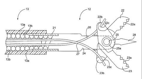
pair of axially displaceable control wires extending therethrough. The control
wires
may be flexible and longitudinally inelastic, and may be formed from metal
such as
steel. The control wires are coupled to on their proximal ends to a portion of
the
handle and on their distal ends to a portion of the end effector assembly.
[003] An endoscopic medical procedure is typically accomplished in
connection with an endoscope which is inserted into a body and guided by
manipulation to the procedure site. The endoscope typically includes a long
narrow
flexible tube with an optical lens and a narrow lumen for receiving the
endoscopic
medical device, for example a biopsy forceps. The practitioner guides the
endoscope
1
CA 02549187 2012-07-24
to the procedure site, with appropriate imaging through use of the optical
lens, and
inserts the endoscopic medical device through the lumen of the endoscope to
the
procedure site. While viewing the procedure site through use of the optical
lens of
the endoscope, the practitioner manipulates the actuating handle cause the end
effector, for example, biopsy forceps jaws, to perform the medical procedure.
After
the procedure, the practitioner and/or an assistant carefully withdraws the
medical
instrument from the endoscope.
[004] The distal assembly of many endoscopic instruments include a clevis
that connects the distal assembly to the elongate member and also holds the
distal
end effectors, such as biopsy forceps jaws. One current cast clevis design has
two
opposing distal arms. An axle protrudes from one of the distal arms, while the
opposing distal arm has a through hole. When the jaws are placed onto the
axle, the
opposing distal arm is folded over to place the axle in the through hole, and
then the
end of the axle protruding past the through hole is riveted so as to prevent
the distal
arms from spreading. Other clevis arrangements are shown and described in U.S.
Patent No. 5,716,374.
SUMMARY OF THE INVENTION
[005] A clevis assembly is disclosed for a medical instrument. The medical
instrument includes a clevis having a base and a plurality of arms extending
from the
base and an axle to extend between the plurality of arms. Each of the
plurality of
arms is configured to accommodate a portion of the axle and an end of the axle
includes a flared portion to engage an outer surface of one of the plurality
of arms.
[006] Also disclosed is a medical instrument including a handle portion, an
end effector assembly, and an elongate member connecting the handle portion to
the
end effector assembly. The end effector assembly includes a clevis having a
base
and a plurality of arms extending from the base and an axle to extend between
the
plurality of arms. Each of the plurality of arms is configured to accommodate
a portion
of the axle and an end of the axle includes a flared portion to engage an
outer
surface of one of the plurality of arms.
2
CA 02549187 2009-07-31
[006a] According to one aspect of the invention there is provided a clevis
assembly for a medical instrument comprising: a clevis having a base and a
plurality of arms extending from the base; and an axle to extend between the
plurality of arms, wherein each of the plurality of arms is configured to
accommodate a portion of the axle, wherein an end of the axle includes a
flared
portion to engage a first outer surface of one of the plurality of arms,
wherein the
axle has a deformed portion at an end of the axle opposite the flared portion,
wherein the deformed portion lies on a second outer surface of another of the
plurality of arms, and wherein the second outer surface is not a surface
facing a
hole or a U-shaped groove to receive the axle, the hole or U-shaped groove
being defined by the another of the plurality of arms.
[006b] According to another aspect of the invention there is provided a
medical instrument comprising: a handle portion; an end effector assembly; and
an elongate member connecting the handle portion to the end effector assembly,
wherein the end effector assembly comprises: a clevis having a base and a
plurality of arms extending from the base; and an axle to extend between the
plurality of arms; wherein each of the plurality of arms is configured to
accommodate a portion of the axle, wherein an end of the axle includes a
flared
portion to engage a first outer surface of one of the plurality of arms,
wherein the
axle has a deformed portion at an end of the axle opposing the flared portion,
wherein the deformed portion lies on a second outer surface of another of the
plurality of arms, and wherein the second outer surface is not a surface
facing a
hole or a U-shaped groove to receive the axle, the hole or U-shaped groove
being defined by the another of the plurality of arms.
[007] According to another aspect of the invention there is provided a
method of manufacturing an end effector assembly of a medical instrument, the
method comprising: manipulating a sheet of material to form a clevis, the
clevis
including a base and a plurality of arms extending from the base; and mounting
an axle to the plurality of arms, the axle holding an end effector and
including a
first flared portion at a first end of the axle; wherein mounting the axle
includes
engaging the first flared portion with an outer surface of one of the
plurality of
arms; and wherein each of the plurality of arms defines a U-shaped groove to
receive the axle.
3
CA 02549187 2009-07-31
[008] According to another aspect of the invention there is provided a
clevis for a medical instrument comprising: a base; and a plurality of arms
extending from the base, at least one of the plurality of arms defining a
groove
configured to receive an axle.
[009] According to another aspect of the invention there is provided a
medical instrument comprising: a handle portion; an end effector assembly; and
an elongate member connecting the handle portion to the end effector assembly,
wherein the end effector assembly comprises: a base; and a plurality of arms
extending from the base, at least one of the plurality of arms defining a
groove
configured to receive an axle.
[010] According to another aspect of the invention there is provided a
method of manufacturing a clevis of a medical instrument, the method
comprising: manipulating a sheet of material to form a clevis, the clevis
including
a base and a plurality of arms extending from the base, at least one of the
plurality of arms defining a groove configured to receive an axle.
[011] According to another aspect of the invention there is provided a
clevis for a medical instrument comprising: a base; and a plurality of arms
extending from the base, wherein at least one of the plurality of arms
includes a
reinforcing portion.
[012] Additional objects and advantages of the invention will be set forth
in part in the description which follows, and in part will be obvious from the
description, or may be learned by practice of the invention. The objects and
advantages of the invention will be realized and attained by means of the
elements and combinations particularly pointed out in the appended claims.
[013] It is to be understood that both the foregoing general description
and the following detailed description are exemplary and explanatory only and
are not restrictive of the invention, as claimed.
3a
CA 02549187 2009-07-31
BRIEF DESCRIPTION OF THE DRAWINGS
[014] The accompanying drawings, which are incorporated in and
constitute a part of this specification, illustrate embodiments of the
invention and
together with the description, serve to explain the principles of the
invention.
[015] Fig. 1 is a schematic view of a medical instrument according to an
embodiment of the present invention.
[016] Fig. 2 is a partial cross-sectional view of an end effector assembly
of the medical instrument of Fig. 1.
[017] Fig. 3A is a perspective view of a clevis of the end effector
assembly of Fig. 2.
[018] Fig. 3B is a schematic view of a production layout of the clevis of
Fig. 3A.
[019] Fig. 3C is a perspective view of an axle for use with the clevis of
Fig. 3A.
[020] Fig. 4A is a perspective view of a clevis of an end effector
assembly for use in a medical instrument, according to another embodiment of
the present invention.
[021] Fig. 4B is a schematic view of a production layout of the clevis of
Fig. 4A.
[022] Fig. 4C is a perspective view of an axle for use with the clevis of
Fig. 4B.
DESCRIPTION OF THE EMBODIMENTS
[023] Reference will now be made in detail to embodiments of the
invention, examples of which are illustrated in the accompanying drawings.
Wherever possible, the same reference numbers will be used throughout the
drawings to refer to the same or like parts.
[024] An exemplary embodiment of an endoscopic instrument 10 is
depicted in Fig. 1. The endoscopic instrument 10 includes a handle portion 11
and an end effector assembly 12 connected to each other by a flexible elongate
member 13. Control wires 26, 27 extend between the handle portion 11 and the
end effector assembly 12 through the flexible elongate member 13.
4
CA 02549187 2006-06-02
WO 2005/060834 PCT/US2004/038237
[025] The handle portion 11 includes a ring portion 11 c disposed at the
proximal end of an elongate portion 11 b. A spool portion 11 a is disposed
around
the elongate portion 11 b and is configured to move longitudinally relative to
the
elongate portion 11 b. The spool portion 11 a is connected to the control
wires 26,
27. The elongate member 13 may include an inner coiled portion 13b (see Fig.
2)
surrounded by an outer covering or jacket portion 13a. The inner coiled
portion 13b
is hollow, and configured to accommodate control wires 26, 27 and allow the
longitudinal movement of the control wires 26, 27 therethrough. The handle
portion
11 and elongate member 13 described are exemplary only and may have other
suitable configurations.
[026] An exemplary embodiment of an end effector assembly 12 is depicted
in Fig. 2. The end effector assembly 12 has a clevis 21 which is coupled, on
its
proximal end to the elongate member 13. The end effector assembly 12 also has
a
pair of forceps jaws 22, 23 that may be substantially similar in shape and
appearance.
[027] The clevis 21 has a pair of clevis arms 24 which accommodate an
axle 25 therethrough. Jaws 22, 23 are rotatably mounted on the portion of the
axle
25 between the clevis arms 24. Each jaw 22, 23 has a distal cutting edge 22a,
23a,
a proximal tang 22b, 23b, and a mounting hole 22c, 23c on the proximal tang
22b,
23b. The proximal tangs 22b, 23b are each coupled to the distal end of a
respective control wire 26, 27 which run through the hollow center of the
elongate
member 13. Manipulation of the handle portion 11, for example the movement of
the spool portion 11 a relative to the elongate portion 11 b, results in the
longitudinal
movement of the control wires 26, 27 relative to the elongate member 13. The
movement of the control wires 26, 27 acts on the proximal tangs 22b, 23b of
the
jaws 22, 23, resulting in the opening and closing of the jaws 22, 23 relative
to each
other. The end effector assembly 12 may also include a flat knife or spike 28
which
is mounted on the distal end of the clevis 21 and disposed between the jaws
22,
23.
[028] An exemplary embodiment of a clevis is shown in Figs. 3A-3C. The
clevis 21 may be formed as a unitary molded or cast member. The clevis 21 has
a
proximal end 29 from which the clevis arms 24 extend, and the proximal end 29
may be configured so that is can be crimped or welded to the distal end of the
CA 02549187 2006-06-02
WO 2005/060834 PCT/US2004/038237
elongate member 13. For example, the proximal end 29 can be wrapped to form a
cylinder or a broken cylinder 33 configured to centrally receive, or be
received by,
the elongate member 13. Each of the clevis arms 24 have a mounting hole 30 for
receiving an axle 25. The clevis arms 24 are joined by a substantially
orthogonal
cross member 31 disposed distal to the proximal end and proximal to the
mounting
holes 30. A central tab 32 may extend distally from the cross member 31 to
spike
28 and be provided with a third mounting hole 30 that is located at a
substantially
similar position to the other mounting holes 30 on the clevis arms 24. This
third
mounting hole 30 may improve stability of the axle 25. The jaws 22, 23 may be
mounted on both sides or either side of the central tab 32 with the spike 28
extending between the jaws 22, 23. As will be described in connection with the
embodiment of Figs. 4A-4B, clevis 21 may include stiffening ribs along the
arms 24
to provide additional strength and make the arms 24 less flexible in certain
directions.
[029] As shown in Fig. 3B, the clevis 21 may be stamped from a stainless
steel sheet 34 which is cut (stamped) to form at least two relatively broad
proximal
bases 39 and at least two relatively narrow substantially parallel clevis arms
24,
one arm 24 extending from each base 39. The cut sheet is formed by bending the
cross member 31 on either side of the central tab in an "S" configuration so
that the
mounting holes 30 of each clevis arm 24 and the central tab 32 are aligned
substantially coaxially with each other. The steel sheet 34 may also be cut so
that
a distal spike 28 may extend from the central tab 32. The arms 24 may be bent
inward at an angle, for example, of approximately 15 degrees along a portion
24a
just proximal of the mounting holes 30. The at least two proximal bases 39 are
bent towards each other to form a bifurcated cylinder 33. The bifurcated
cylinder
33 can be crimped, welded, or otherwise affixed to the distal end of the
elongate
member 13.
[030] An axle 25 with one flared end or flange 25a as shown in Fig. 3C is
then provided. The axle 25 may have a substantially circular cross-section
with a
substantially constant inner circumference (e.g., inner diameter) for the
entire
length of the axle 25. The flared end or flange 25a may also have a
substantially
circular cross section that tapers from a maximum outer circumference (e.g.,
outer
diameter) at the portion configured to contact an outer surface of the arms
24, to a
6
CA 02549187 2006-06-02
WO 2005/060834 PCT/US2004/038237
minimum circumference (e.g., inner diameter) substantially similar to the
either the
outer circumference of the non-flared portion of the axle 25 or the inner
circumference of the axle 25. The end effector assembly 12, for example jaws,
may be placed on the axle 25 via the end 25b opposite the flared end or flange
25a. The end effector assembly 12 may be placed on the axle 25 after placing
end
25b of the axle 25 through the first mounting hole 30, and then the end 25b
may be
placed through the other mounting hole 30. In embodiments wherein there is a
third arm 24 between the outer arms 24, end 25b may first be placed through
one
mounting hole 30, a portion of the end effector assembly 12, for example a
jaw,
may be placed on the axle 25. The end 25b may then be placed through the
mounting hole on the central arm 24, the other portion of the end effector
assembly
12 may then be placed on the axle 25, and then the end 25b may be placed
through the remaining mounting hole 30. At this time, the flared end or flange
25a
may contact the outer surface of an art-n 24, while the outer surface of the
rest of
the axle 25 may contact the inner surfaces of the mounting holes 30 and rotate
within the mounting holes 30. The other end 25b of the axle 25 is then flared
out,
or otherwise configured, to lodge the axle 25 in the arms 24 of the clevis 21,
making the axle 25 and the end effector assembly 12 relatively difficult to
dislodge
from the mounting holes 30, for example, during the actuation of the end
effector
assembly 12. In such a state, portions of the end 25b are in contact with the
outer
surface of an arm 24 and flared out portions of the end 25b may also be
disposed
within the adjacent mounting hole 30 (i.e., the circumference of the end 25b
in the
mounting hole 30 may increase and form a press-fit with the mounting hole 30
due
to the flaring out of the rest of the end 25b).
[031] In various embodiments, the inner portion of the axle 25 may be
hollow or solid, and may have any desired cross-sectional shape, and may even
have a cross-sectional shape that varies along its length. The outer surface
of the
axle 25 may not be smooth. That surface may have grooves or other features,
for
example, to assist in the alignment of portions of the end effector assembly
12 on
the axle 25. That surface may also have a roughened surface at certain
portions to
interact with portions of the clevis 21 defining holes 30 and thereby limit
its
rotational motion relative to those arms. The flared end or flange 25a may not
be
disposed around the entire circumference of an end of the axle 25, but may
instead
7
CA 02549187 2006-06-02
WO 2005/060834 PCT/US2004/038237
be a tab or a plurality of tabs disposed around the end of the axle 25 that
function
substantially similarly to the flange 25a. In addition to being flared out,
the other
end 25b of the axle 25 may be threaded so that a nut may be screwed on, may be
configured to be riveted, or may be configured to accept an adhesive.
[032] The design of the axle 25 and its use during the forming of clevis 21
may improve manufacturability of the end effector assembly 12 by utilizing the
placement of the axle 25 in the mounting holes 30 as an alignment aid, if
necessary, for the clevis 21 and the jaws 22, 23. Furthermore, by flaring out
each
end 25a, 25b of the axle 25, the axle 25, and anything mounted to the axle 25,
for
example, the jaws 22, 23, may be prevented from axially shifting in the
mounting
holes 30. However, in some cases, it may be desirable to flare out the ends
25a,
25b of the axle 25 in a manner so as to allow axial shifting of the axle 25
and/or the
jaws 22, 23 in the mounting holes 30.
[033] The design of the axle 25 with a flared end 25a may improve the
manufacturability of the axle 25 by utilizing the central orifice of the axle
25 as an
alignment in the production of the axle 25. For example, manufacturability may
be
improved because the design of the axle 25 may ensure riveting accuracy
axially.
With this design of the axle 25 with an orifice, rework or replacement of the
axle 25
is possible during manufacturing, possibly avoiding disposal of the entire
axle or
device.
[034] Another exemplary embodiment of a clevis is shown in Figs. 4A-4B.
The clevis 121 is formed as a unitary molded or cast member and has a
substantially cylindrical proximal end 129 from which the clevis arms 124
extend.
The proximal end 129 of the clevis 121 is wrapped to form a cylinder or a
broken
cylinder 133, and may be crimped, welded, or otherwise affixed to the distal
end of
the elongate member 13. The clevis arms 124 each define at least one U-shaped
groove 130 for receiving an axle pin 125 shown in Fig. 4C. The clevis arms 124
are
joined by a substantially orthogonal cross member 131 disposed proximal to the
U-
shaped grooves 130. A central tab 132 may extend distally from the cross
member
131 and be provided with a third U-shaped groove 130. The jaws 22, 23 may be
mounted on both sides or either side of the central tab 132 with a spike 128
extending between the jaws 22, 23. The clevis arms 121 may also include
stiffening ribs 135 on the outside surfaces 136 of each of the clevis arms 121
so as
8
CA 02549187 2006-06-02
WO 2005/060834 PCT/US2004/038237
to provide additional strength, and make the arms 121 less flexible in certain
directions.
[035] As shown in Fig. 4B, the clevis 121 may be stamped from a stainless
steel sheet 134 which is cut (stamped) to form at least two relatively broad
proximal
bases 139 and at least two relatively narrow substantially parallel clevis
arms 124,
one arm 124 extending from each base 139. The cut sheet is formed by bending
the cross member 131 on either side of the central tab in an "S" configuration
so
that the U-shaped grooves 130 of each clevis arm 124 and the central tab 132
are
aligned substantially coaxially with each other. The steel sheet 134 may also
be
cut so that a distal spike 128 may extend from the central tab 132. The arms
124
may be bent inward at an angle, for example, of approximately 15 degrees along
a
portion 124a just proximal of the U-shaped grooves 130. The at least two
proximal
bases 139 are bent towards each other to form a bifurcated cylinder 133. The
bifurcated cylinder 133 can be crimped, welded, or otherwise affixed to the
distal
end of the elongate member 13.
[036] The U-shaped grooves 130 are configured to receive and retain an
axle pin 125, for example, as depicted in Fig. 4C, configured to accommodate
the
jaws 22, 23. The axle pin 125 may be snapped or otherwise affixed into place
in
the U-shaped grooves 130. For example, the U-shaped grooves 130 may have
protrusions or bumps 137 (shown in Fig. 4B) on the inside portions of their
ends
configured to retain the axle pin 125. Bumps 137 would overlie pin 125 once
pin
125 is in place within grooves 130. Alternatively or additionally, pin 125 may
be
bonded within grooves 130 with a suitable biocompatible adhesive. Other
contemplated methods of retaining the axle pin include spot welding, seam
welding,
brazing, resistance welding of contact areas, and any other method known in
the
art.
[037] The jaws 22, 23 may be placed on the axle pin 125, and then the axle
pin 125 may be placed in the U-shaped grooves 130, simplifying the process of
both installing the jaws 22, 23 and aligning axle pin 125 in the U-shaped
grooves
130. As in the embodiment of Figs. 3A-3C, this configuration is also tolerant
of
slight axial misalignments of the U-shaped grooves 130 during the bending of
the
sheet 134.
9
CA 02549187 2006-06-02
WO 2005/060834 PCT/US2004/038237
[038] The stiffening ribs 135 may be stamped on the sheet 134, and
displace some of the material on the inside surface 138 of the sheet to the
outside
surface 136. This configuration imparts greater stability on the arms 124, and
makes it more resistant to bending or torqueing either due to outside forces,
or due
to the actuation of the end effector assembly 112.
[039] The pin 125 may have a substantially circular cross-section with a
substantially constant inner circumference (e.g., inner diameter) for the
entire
length of the pin 125. The flared ends or flanges 125a, 125b may also have a
substantially circular cross section that tapers from a maximum outer
circumference
(e.g., outer diameter) at the portion configured to contact an outer surface
of the
arms 24, to a minimum circumference (e.g., inner diameter) substantially
similar to
either the outer circumference of the non-flared portion of the pin 125 of the
inner
circumference of the pin 125. The end effector assembly 12, for example jaws,
may be placed on the pin 125, and then the pin 125 may be inserted into the
grooves 130. At this time, the flared ends or flanges 125a, 125b may contact
the
outer surface of an arm 24, while the outer surface of the rest of the pin 125
may
contact the inner surfaces of the grooves 130 and rotate within the grooves
130. In
such a state, the pin 125 and the end effector assembly 12 may be relatively
difficult to dislodge from the grooves 30, for example, during the actuation
of the
end effector assembly 12. Portions of the pin 125 may also be in contact with
bumps or protrusions 137 which may assist in retaining the pin 125 in the
grooves
130.
[040] In various embodiments, the inner portion of the pin 125 may be
hollow or solid, and may have any desired cross-sectional shape, and may even
have a cross-sectional shape that varies along its length. The outer surface
of the
pin 125 may not be smooth. That surface may have grooves or other features,
for
example, to assist in the alignment of portions of the end effector assembly
12 on
the pin 125. That surface may also have a roughened surface at certain
portions to
interact with portions of the clevis 121 defining U-shaped grooves 130 and
thereby
limit its rotational motion relative to those arms 124. The flared ends or
flanges
125a, 125b may not be disposed around the entire circumference of an end of
the
pin 125, but may instead be a tab or a plurality of tabs disposed around the
ends of
the pin 125 that function substantially similarly to the flange 25a in Fig.
3C.
CA 02549187 2006-06-02
WO 2005/060834 PCT/US2004/038237
Furthermore, instead of being flared out, either end 125a, 125b of the pin 125
may
be threaded so that a nut may be screwed on, may be configured to be riveted,
or
may be configured to accept an adhesive.
[041] There have been described and illustrated herein several
embodiments of a clevis for an endoscopic instrument and methods of making the
same. While particular embodiments of the invention have been described, it is
not
intended that the invention be limited thereto, as it is intended that the
invention be
as broad in scope as the art will allow and that the specification be read
likewise.
[042] Thus, while particular materials have been disclosed, it will be
appreciated that other materials could be utilized. For example, the disclosed
clevises may be formed of any suitable biocompatible material including
various
metals and non-metals. In addition, while cylindrical portions have been shown
as
incomplete or broken cylinders, it will be recognized that welding, soldering,
brazing, or other operations may be used to complete the cylindrical portions
if
desired. For example, the clevis and end effector may not only be stamped out
of
steel, but may also be cast, molded, or machined out of bronze, plastics,
metals,
ceramics, or other suitable materials known in the art. Additionally, the jaws
may
be substantially similar in shape to each other, however, they may also be
different
in configuration from each other.
[043] In a further example, while the clevis is shown with respect to use in a
biopsy forceps instrument, the clevis could be used with any of a variety of
end
effectors as part of any endoscopic or non-endoscopic medical device,
including,
for example, clamp, scissors, dissectors, graspers, etc. In various
embodiments,
the invention is not limited to use in endoscopic procedures or medical
instruments,
but may also be used in any other medical procedure (e.g., gastrointestinal,
urological, gynecological, cardiological, etc.) or non-medical procedure, or
in
medical or non-medical instruments.
[044] Moreover, while particular configurations have been disclosed in
reference to the mounting holes and the spike, other configurations could be
used
as well. In yet another example, any of the features disclosed in the
specification
may be rearranged to be on any other portion disclosed in the specification.
For
example, a clevis may have arms where at least one of the arms has a mounting
hole, while at least one other arm has a U-shaped grooves. It will therefore
be
11
CA 02549187 2012-07-24
appreciated by those skilled in the art that yet other modifications could be
made to
the provided invention.
[045] Other embodiments of the invention will be apparent to those skilled in
the art from consideration of the specification and practice of the invention
disclosed
herein. The specification and examples are exemplary only.
12