Note: Descriptions are shown in the official language in which they were submitted.
CA 02549371 2006-05-23
A GROUND OPENING DEVICE
TECHNICAL FIELD
This invention relates to a ground opening device.
BACKGROUND ART
Modern agricultural methods commonly involve the planting of large areas of
ground
with the same crop. In such instances the ideal situation, from a crop
management
viewpoint, is for all the plants in the crop to grow at the same rate so that
the entire
crop can be treated as though It were a single plant.
The key to this is consistent seed germination and seedling emergence for all
plants
10. in the crop. This requires that seeds must be sown at a consistent depth
in the soil.
When seeds are sown individually by hand this is not a significant problem.
However,
it can be a problem when, as is commonly the case, the seeds are sown
mechanically.
Any large area of ground (plot) for seeding is likely to contain a range of
soil
conditions. The composition or type of. soil may change, as may the soil
moisture
content and degree of compaction. These and other factors can influence the
resistance of the soil to penetration by the seeding apparatus. Therefore, a
seeding
'machine set to sow seeds at a particular depth in one region of the plot may
not sow
at the same depth in another region, leading to variations in seed germination
and
seedling emergence.
Tillage of soil, for example by ploughing, has the effect of breaking up and
loosening
the soil. It may also produce greater homogeneity of the soil by mixing soil
from
surrounding areas together. Tilled soils are often levelled to some extent,
commonly
by use of a harrow or some form of raking of the soil surface, prior to
seeding.
1
CA 02549371 2006-05-23
Typically a seed drill opener, towed behind a tractor or other mechanised farm
vehicle
is then used to plant the seed. A seed drill opener will usually have one or
more
opening devices, such as discs, blades, knives or tines, to open a slot in the
ground.
The depth of the slot, and in turn the depth of planting of the seed, is then
determined
by the amount of force applied downwardly onto the opening device.
If the soil has been loosened by tillage, springs of various types may be
sufficient to
provide the necessary downward force =and to allow the opening device to rise
and fall
in response to small changes in the surface topology.
Generally the downward force on the opening device is increased until the
desired
depth of penetration is achieved. Further penetration is usually prevented by
use of a
=-depth-limiting device, such as a gauge wheel, which is rigidly attached to
the opening
device. The gauge wheel is adjusted to sit on the surface of the ground when
the
opening device is at the required depth, thus preventing the opening device
from
being lowered beyond that point.
.15 In practice an additional load may be placed onto the opening, device in
order to
compensate for small variations in soil conditions.
A disadvantage with this method Is that the amount of addifional force
required is a
matter of judgement and therefore consistency of depth penetration over the
whole
plot cannot be assured
While an effect of tilting and harrowing of the soil is to reduce the
variability of the soil
condi#ions over the plot, nevertheless variations will remain and some
inconsistency
of depth for seeding can occur.
Increasingly, moreover, the practice of tillage of soils is being considered
less
desirable. Not only is It expensive and fime consuming, but also in many
regions it is
believed to be contributing to degradation of the environment through
increased rates
2
CA 02549371 2006-05-23
of soil erosion, loss of soil moisture content and leaching of essential
minerals and
nutrients from the opened soil.
In such regions the seeds are planted directly into non-tilled ground. In non-
tiilage
applications the concept ts to limit or minimise the disturbance of the
surface and the
soil. Generally plant and other material on and above the surface is left
intact,
removed or reduced without disturbing the surface If possible. The seeds can
then be
planted using a seed driil opener adapted for use in non-tilled soils.
Aspects of seed drili openers and their use in non-filled soils are disclosed
in US
4,275,671, US 5,269,237 and US 6,644,226.
Drill seed openers for use in non-tilled soil must cope with greater
variations in the
force required to penetrate the soil and surface material than in the case of
tilled soil.
Firstly the force required to penetrate non-tilled ground will in general be
greater than
the force required to penetrate the same groUnd that has been loosened by
tillage.
Secondly, the variability of soil conditions has not been ameliorated by
tillage.
Thirdly, there are likely to be greater surface irregularities in non-tilled
soils, as tilling
and harrowing will not have levelled these out.
Therefore the seed drill opener operating in non-tilled soil must use larger
forces and
cope with greater variation in conditions than in tilled soil.
A problem with the current operation of a seed drill opener is that there is
no way of
compensating for all variations of soil conditions even in tilled soils. This
[s a much
greater problem for seeding in non-tilled soils, where the forces and
variations in
conditions are much greater.
It is an object of the present invention to address the foregoing problems or
at least to
provide the public with a useful choice.
3
CA 02549371 2006-05-23
All references, including any patents or patent applications cited in this
specification
are hereby incorporated by reference. No admission is made that any reference
constitutes prior art. The discussion of the references states what their
authors
assert, and the applicants reserve the right to challenge the accuracy and
pertinency
of the cited documents. lt will be clearly understood that, although a number
of prior
art publications are referred to herein, this reference does not constitute an
admission
that any of these-documents form part of the common general knowledge in the
art, in
New Zealand or in any other country.
It is acknowledged that the term 'comprise' may, under varying jurisdictions,
be
attributed with either an exclusive or an inclusive meaning. For the purpose
of this
specification, and 'unless otherwise noted, the term 'comprise' shall have an
inclusive
meaning - i.e. that it will be taken to mean an inclusion of not only the
listed
components, it directly references, but also other non-specified components or
elements. This rationale will also be used when the term 'comprised'
or'comprising'
is used in relation to one or more steps in a method or process.
Further aspects and advantages of the present invention will become apparent
from
the ensuing description which is given by way of example only.
DtSCt.OSURE OF INVENTION
According to one aspect of the present invention there is provided a ground
opening
device which includes,
a ground-penetrating element configured to penetrate a ground surface,
a down drive element corlfigured to apply a downward force to the ground-
penetrafing
element,
a reaction force sensor configured to sense a ground reaction force in
response to
the action of the ground-penetrating element,
4
CA 02549371 2006-05-23
characterised in that
the ground opening device includes a controller configured to adjust the
downward
force on the ground-penetrating element in response to the sensed ground
reaction
force.
According to another aspect of the present invention there is provided a
method of
controlling a ground opening device having a ground-penetrating element, a
down
drive element, a ground reaction force sensor and a controller,
characterised by the steps of
a) applying a downward force to the ground-penetrating element using the down
drive element, and
b) sensing a ground reaction force using the ground reaction force sensor; and
c) using the controller to adjust the downward force of the ground-penetrating
element in response to the sensed ground reaction force.
Aground-opening device may be considered to be any implement that breaks the
surface of the ground and penetrates to some depth into the soil. Spades,
forks,
hoes and driiis are all familiar ground opening devices in domestic gardening.
On a larger scale, as is common in modern agricultural practice, the ground
opening
device may be a plough or harrow, among others. Such ground-opening devices
are
used to prepare large areas of ground and numerous specialised devices have
been
constructed for this purpose.
In a preferred embodiment of the current invention the ground-opening device
is a
seed drill opener. Seed drili openers are devices used to open the ground and
insert
seeds, usually at a predetermined depth. Seed drilt openers usually include a
device
for covering the implanted seed and closing the opening as part of the seeding
5
CA 02549371 2006-05-23
operafion. The seed drill opener is normally attached to a vehicle, such as a
tractor,
which pulls the seed drill opener over the ground.
Reference will be made throughout this specification to a ground-opening
device
being a seed dritl opener. However, those skilled in the art will be aware
that there
are other forms of ground opening devices, such as ploughs, harrows and hoes
among others, and that reference to a seed drill opener only should not be
seen as
limiting.
Seed drill openers are normally configured for a particular task. For example
the
design and operation of a seed drill opener will depend on such things as
whether it is
to be used on. titled or untiiied ground, and the nature of the crop to be
sown as
different seeding depths may be required for different crops.
In a preferred embodiment of the current invention the ground-opening device
is a
seed drill opener for seeding non-filled ground.
US 4,275,671, US 5,269,237 and US 6,644,226 all disclose seed drill openers
configured for use in non-tilled ground.
Reference will be made throughout this specification to a ground-opening
device
being a seed drill opener configured for seeding non tilled ground. However,
those
skilled in the art will be aware that there are other forms of seed drill
openers, such as
those for use on tilled ground, and that reference to a seed drill opener
configured for
use on non-tilted ground only should not be seen as limiting.
While the current invention may be used to advantage with a wide range of
ground
opening devices, It Is particularly advantageous (as will be outlined below)
when used
with a seed driii opener on non-tilled ground.
Proper germination of a seed depends, among other things like soil temperature
and
moisture, on the depth of planting of the seed. A seed drill opener must
therefore
6
CA 02549371 2006-05-23
provide a means of opening the ground to the required depth and implanting the
seed.
Opening the ground is achieved by use of a ground-penetrating element. It is
well
known that practically any substantialiy rigid implement may be used to
penetrate the
ground, particuiariy if sufficient force is applied. However, in agriculture
ground-
penetrating elements are normally configured to achieve particuiar results
depending
on the task to be performed and the .nature of the ground. Common examples of
ground-penetrating elements used in agriculture include blades, knives, discs
and
tines, among others.
9n a preferred embodiment of the current inven#ion the ground-penetrating
element
includes a disc.
In an alternate embodiment of the. current invention the ground-penetrating
element
includes a=tine. The tine.may be a rigid -Dr non-rigid prong, often with a
pointed end,
which is pushed into the soil.
Reference will be'made throughout this specification to a ground-penetrating
element
as including a disc. However, those skilled in the art will be aware that
other forms of
ground-penetrating elements, such as tines, knives or blades, could be
included,
(either alone or In combination with a disc or other such element), and that
reference
to the ground-penetrating element as including a disk only should not be seen
as
limiting.
Preferably substantially flat discs are used in seed drill openers for use on
non-tilled
ground. Curved discs may be used, although these create wider openings in the
ground. In part, the intent in non-tillage seeding is to minimise the
disturbance to the
ground and surface, thus minimising the potential for erosion and maintaining
the
moisture content and nutrient levels of the soil. Therefore a thin narrow
incision, such
as may be obtained by drawing a substantiafly vertically oriented
substantially flat disc
7
CA 02549371 2006-05-23
In a=straight line through the soil, may provide an advantage in reducing the
amount
of disturbance to the ground.
Each ground-penetrating element may include one or more discs, or a
combination of
one or more discs with one or more blades. One such combination for use in non-
tiliage operations includes a flat disc as described above, with one or more
side
blades configured to contact the disc. This arrangement can be-used to clear
stubble
and other surface debris from the side of the disc, as well as to. create a
contoured
incision which may be used to. advantage, for example to allow the =sowing of
seeds at
one level and the deposition of fertiliser at another.
In other non-tillage applications a coulter may be used to cut surface.
stubble and
partially open the soil ahead of the seed drill opener. A coulter, which Is a
type of
ground-penetrating element, is typically a broad disc or combination of discs,
often
with a sharp, fluted circumference.
Drawing a coulter through the soil ahead of the seed drill opener has the
effect of
loosening the soil In a limited channel (partial tillage) ahead of the ground-
penetrating
element of the seed drill opener. However, use of a coulter will normally
result In
greater ground disturbance than use of the flat disc ground-penetra#ing
element
described above.
In a preferred embodiment- of the current invention the ground-opening device
can
deliver seeds. For example the ground-penetrating element may have a seed
delivery
tube associated with it such that a seed can be deposited at a consistent
position
relative to the disc.
In a preferred embodiment of the current invention the ground-opening device
can
deliver fertiliser. As for the seed tube described above, the ground-
penetrating
element may have a fertiliser delivery tube associated with it such that
fertiliser can be
8
CA 02549371 2006-05-23
deposited at a consistent position (normally near but not at the position of
the seed
delivery position) relative to the disc.
Considerable force is required to drive a ground-penetrating element, such as
a disc
and side blade, into non-tilled ground. The amount of force required depends
on the
resistance of the soil and on the desired depth of penetration. Less force is
required
for tilled land as the tillage process loosens the soil.
In non-fillage operation a force of up to 5000 N is required to force a normal
sized
disc to seeding depth in hard ground.
Commercial seed drill openers generally have a number of discs on each frame.
Hence, for example, a seed drill opener having 20 discs wiil require around
100,000 N
of force to provide full penetration of all discs into non-tilled soil.
The required downward force can be achieved in part by the weight of the seed
driil
opener itself. The seed drill opener normally has a heavy rigid frame to which
the
Aiscs are attached. The seed drill opener may also include a seed bin or
hopper.
Force derived from the weight of the frame must be applied to achieve correct
operation of the seed drill opener. This downward force, which is transferred
to the
ground-penetrating elements, is provided by a down drive element.
Reference to a down drive element throughout this specification should be
understood to refer to any device which applies a downward force directly or
indirectly
onto a ground-penetrating element.
In the most basic application the down drive element may be provided by
placing
additional. weights onto the seed drill opener until the necessary penetration
is
achieved. This arrangement however does not allow for any adjustment of the
downward force and therefore cannot be used (easily) to modify the downward
force
in response to changes in the soil condition.
9
CA 02549371 2006-05-23
In a preferred embodiment of the current invention the down drive element
includes a
hydraulic ram.
Reference to a hydraulic ram throughout this specification should be
understood to
mean any device that regulates and uses hydraulic pressure to transmit or
apply a
force to an object.
In alternate embodiments the down drive element may include a pneumatic ram, a
spring or a resllient, buffer, or any combination of these. Springs andfor
resilient
buffers may be used with hydraulic rams in order to transmit the forces from
the
hydraulic rams to the ground-penetrating elements.
Reference will be made throughout this specification to a down drive element
as
including a hydraulic ram. However, those skilled in the art will be aware
that there
are numerous forms,of down drive elements that could be included (either alone
or in
combination with a hydraulic ram); such as pneumatic rams, springs and
buffers, and
that reference to the down drive element-as including a hydraulic ram only
should not
be seen as limiting.
In a preferred embodiment of the invenfion each ground-penetrating element is
individually connected to a hydraulic ram.
The source of oil. pressure is common to each hydraulic ram and Is typically
derived
from an agricultural tractor of other vehicle used to pull the seed driil
opener along.
The oil pressure system may operate in common with one or more pressure
accumulators. The accumulators provide volumetric changes and cushioning that
allows the ground-penetrating elements to rise and fall as they follow
variations in the
height of the soil surface without significantly changing the overall
hydraulic pressure
of the oil.
CA 02549371 2006-05-23
In alternate embodiments a number of. ground-penetrating elements may be
connected together on a rigid frame, with the frame having an individual
connection to
the hydraulic ram. In this way the same down force can be applied to a number
of
discs at the same time. This arrangement is simpler than having each disc
connected
directly to the hydraulic pressure regulator device, and therefore more
economical to
make.
The seed drill opener is typically attached to a tractor having a hydraulic
ram. In use
a downward force is applied by the hydraulic ram individually to each disc on
the seed
drill opener until the disc penetrates the ground to the required depth.
The resistive upward forces of the soil oppose penetration of the ground by
the
ground-penetrating element. Therefore a force greater than the resistive
forces of the
soil must be applied by the. hydraulic ram to the seed drill opener in order
for the seed
drill opener to penetrate into the ground.
The seed drill opener usually Includes a penetration-limiting device.
Reference to a penetration-limiting device throughout this specification
should be
understood to be any device attached to the frame of the ground-opening
machine, or
to the ground-penetrating element, which is configured to reside on the
surface of the
ground without penetrating into it.
The position of the penetration-limiting device is adjusted so that when it is
in contact
with the ground the ground-penetration element will be at the desired
penetration
depth.
Preferably the penetration-limiting device is a gauge wheel, attached to the
disc or the
rigid frame to which the disc is attached.
11
CA 02549371 2006-05-23
Other forms of penetration-limitÃng devÃces such as skids or plates could be
used and
reference to a penetration-limiting device as a gauge wheel only throughout
this
specificatÃon should not be seen as limiting.
An advantage of using a gauge wheel, rather than a skid or plate, is that the
gauge
.5 wheel creates less -rolÃing resistance when drawn across the ground,
placing less load
on the tractor transmission.
The gauge wheel is preset to a fixed position relative to the disc such that
the disc will
be at the correct depth when the gauge wheel is touching the surface of the
ground.
In operatÃon the hydraulic ram applies a down force to the disc so that it
penetrates
'Ãnto the ground until the gauge wheeÃ. Ãs located on the surface of the
ground. It is
then normal practice to- apply an addit;onaà load, through the hydraulÃc ram,
to the
disc.
The gauge wheel prevents the disc from penetrating deeper into the soÃI_ The
purpose of the additional toad is to enable the disc to compensate for any
minor
variatÃons In the resistive forces exerted by the soil.
The loading on the gauge wheel is defined as the ground reaction force. Thus
the
ground reaction force is zero untii the gauge wheel is in contact with the
surface.
The ground reaction force Is initiaÃly set by the operator who selects an
excess force
to apply to the disc so as to keep it at the required depth under the given
conditions.
As the depth of penetration of the disc is fixed by the action of the gauge
wheel, the
additional force becomes a load on the gauge wheel that is equal in magnitude
to the
.upward force exerted by the ground on the gauge wheel.
The ground reactÃon force is not equal to (and generally much less than) the
sum of
the resistive forces of the soil that are overcome in penetrating the soil
with the disc.
12
CA 02549371 2006-05-23
The ground reaction force will alter depending on the soil -conditions
encountered by
the disc. For example, if the soil becomes more compacted (denser) the
resistive
forces. of the soil will increase pushing the disc toward the surface. This
wiil reduce
the. magnitude of the ground reaction force (which is the difference between
the
downward force applied by the hydraulic ram and the sum of the resistive
forces of
the soil),
In an,extreme case the ground reaction force could reduce to zero, indicating
that the
gauge wheel is no longer in contact with the ground, and as a consequence the
disc
is no longer at the correct depth. It is therefore of considerable advantage
to know
.10 =the magnitude of the ground reaction force at all times.
The ground-opening machine includes a reaction force sensor configured to
sense
:the'ground reaction force in response to the action of the ground-penetrating
element.
Reference to a ground reaction force sensor throughout this specification
should be
understood to refer to any apparatus *,or device that is configured to measure
the
ground reaction force.
In a preferred embodiment of the current invention the reaction force sensor
includes
an electronic stain gauge.
In altemative embodiments the ground reaction force sensor may include an
hydraulic
pressure sensor or a pneumatic pressure sensor,
Reference will be made throughout this specification to a ground reaction
force
sensor including an electronic strain gauge. However, those skilled in the art
will be
aware that other forms of reaction force sensors could be included, such as
hydraulic
or pneumatic pressure sensors, or mechanical sensors, and that reference to a
reaction force sensor including an electronic strain gauge only should not be
seen as
limiting.
13
CA 02549371 2006-05-23
Typically the ground reaction force sensor involves electronic strain gauges
mounted
on or in a block that comes under strain as the up-thrust changes. The
electronic
strain gauge produces a voltage in proportion to the measured strain. This
voltage
may be used to determine the amount of force to be applied to the seed drill
in order
to maintain the ground reaction force at or near a pre-set level.
information regarding the sensed ground reaction force, typically in the form
of a
voltage, the magnitude of which is proportional to the ground reaction force
or to a
change in that force, is transmitted to a controller.
Reference to a controller throughout this specification should be understood
to refer
to a device or person used to regulate a function of the ground-opening
device. In
particular the controller is= configured.to adjust the down force on the
ground-
,penetrating element in response to the sensed ground reaction force.
In a- preferred embodiment of the current invention the controller includes an
automated electronic device configured to receive a signal proportional to the
sensed
reaction force from the reaction force sensor and to adjust the down force on
the
ground-penetrating element in response to the received signal.
In an altemate embodiment the controller includes an hydraulic actuator which
is
connected to the reaction force sensor which includes an hydraulic pressure
sensor.
The -controller is configured to adjust the down force on the ground-
penetrating -
element in response to the sensed pressure.
In yet another alternate embodiment of the current invention the controller is
an
operator who manually adjusts the down force on the ground-penetrating element
in
response to the sensed ground reaction force. This may be indicated by various
means, for example a display on a monitor, a pressure gauge or an audio
signal, or
combinations of these among others.
14
CA 02549371 2006-05-23
Reference is made throughout this specification to a controller as an
automated
electronic controller configured to receive a signal from a reaction force
sensor and to
adjust the down force on the ground-penetrating element in response to the
signal.
However, those skilled In the art will knoinr that other forms of controller
may be used,
including an operator; and that reference to a controller as including an
automated
electronic device only should not be seen as limiting.
An advantage of using an electronic strain gauge to sense the ground reaction
force
is that the electronic strain gauge output is in the form of an electronic
signal which is
proportional to the sensed -ioad or a change =in it. This signal can be
processed
electronically and additional information obtained from the analysis.
For example, if the sensed ground reaction force is changing rapidly or
erratically it
may be appropriate for the controller to adjust the =down force based on a
time-
averaged or smoothed value of the sensed response, or introduce some
hysteresis
into the reaction.
an a preferred embodiment of the current invention the controller adjusts the
downward force on the ground-penetrating element in response to the sensed
ground
reaction force such that the reaction force of the penetrati.on-limiting
device is kept
substantially constant at the preset level. In this manner the correct depth
of
penetration, and hence seeding, will be maintained
The ground opening device of the current invention includes a ground reaction
force
sensor to measure changes in the resistive forces encountered by the ground
penetrating element. Information from the sensor is transmitted to the
controller
where the information is processed and used to adjust the force on the ground
penetrating eiement so as to compensate for the change in resistive forces. In
this
manner substantially the same ground reaction force is maintained on the gauge
wheel at all times, thus ensuring the desired penetration depth for sowing the
seed.
1S
CA 02549371 2006-05-23
In a preferred embodiment of the current invention the ground reaction sensor
and
controller can be disabled. For example, the feedback should not be used when
the
ground penetrating disc is lifted from the soil during turning or transport,
or if the
gauge wheel is lifted for any reason other than when in use.
Seed drills using the current invention are provided with a major advantage
over other
devices which do not measure the ground reaction force and therefore have no
way
of knowing how the resistive forces are changing, nor the effect this may be
having on
the sowing depth.
Seed drills using the present invention may adjust the load on the seed driil
so as to
maintain it at or near a pre-determined value. The pre-determined value of the
ground reaction force on the gauge wheel is chosen to provide the desired
depth of
penetration of the seed drill for the prevailing conditions. The use of the
present
invention provides the advantage of continual monitoring of the ground force
reaction
on the gauge wheel and adjustment of it in order to maintain the correct
penetration
under changing soil conditions. In this way seed planted using seed driils
equipped
with the present invention will be at a consistent depth thus helping to
ensure uniform
germination and plant emergence. This is of major economic value to the farmer
as
all plants in the crop grow consistently and can be treated as required at the
same
time.
The use of the current invention provides the greatest advantage when used in
non-
tilled ground, as it is these conditions that the greatest variations in
resistive forces
are likely to be encountered.
16
CA 02549371 2006-05-23
BRIEF DESCRIPTION OF DRAWINGS
Further aspects of the present invention will become apparent from the
following
description which is given by way of example only and with reference to the
accompanying drawings in which:
Fi ure 1 shows a schematic of a ground-opening device; and
Figure 2 shows a schematic of a Force Control System; and
Fiaure 3 shows a schematic of another Force Control Sytem.
BEST MODES FOR CARRYING OUT THE INVENTION
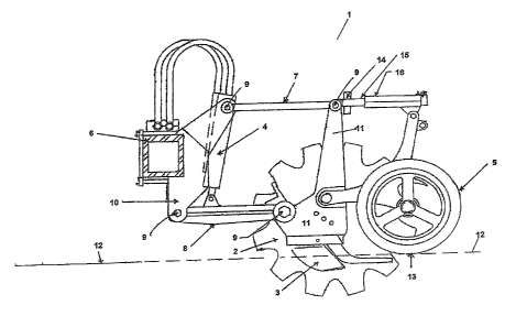
Figure 1 shows a side view of a#ypical non tillage seed drill opener generally
indicated by arrow 1.
The basic elements of the seed drill opener (1) consist of a ground
penetrating disc
(2), one or more rigid ground penetrating side blades (3), an hydraulic ram
(4) and a
gauge wheel (5).
The seed drill opener (1) is attached to a rigid frame (6) that is attached to
a tractor
(not shown). The arms (7) and (8) are attached pivotally at points (9) at each
end of
the arms, one end of each arm to the rigid frame mounting plate (10) and the
other
end of each arm to the rigid frame (11) onto which the ground penetrating disc
(2) is -
attached.
An hydraulic ram (4) attached to. the lower pivoting arm (8) is used to exert
a down
force that causes the disc (2) and side blades (3) to penetrate beneath the
surface
(12) of the ground.
At a certain hydraulic pressure the hydraulic ram (4) will not only cause the
disc (2)
and side blades (3) to penetrate beneath the surface (12), but will also cause
the
17
CA 02549371 2006-05-23
gauge wheel (5) to press upon the ground surface (12).
The configuration of the gauge wheel (5) is such that it will not normally
penetrate the
ground but will press upon its surface (12).
The magnitude of the force exerted by the gauge wheel (on the ground surface)
is
equal and opposite to the up-thrust force (13) from the ground.
The magnitude of the up-thrust (13) is measured by a ground reaction force
sensor
.(14) located in an appropriate component of the mounting bracket (15) for the
gauge
wheel (5). In the example shown in figure 1, the mounting bracket (15) also
has an
adjustable component (16) that facilitates alterations in depth of sowing by
altering
the position of the gauge wheel (5) relafive to the position of the side
blades (3) which
are the devices that implant the seed and fertiliser in the soil.
The system wili remain in equilibrium until the soil's resistance to
penetration
changes. This may occur due to a change in the composition of the soil, the
compaction of the soil, or the moisture content of the soil. Other factors may
also
influence the resistance to penetration, such as the speed at which the disc
is drawn
through the soil.
Any change in soil resistance is -first registered as a change in the
magnitude of the
up-thrust force (13) exerted by the soil on the gauge wheel (5) and recorded
by the
ground reaction force sensor (14).
-20 Typically the ground reaction force sensor (14) includes one or more
electronic strain
gauges mounted on or in a metallic block that come under strain as the up-
thrust (13)
changes. The strain gauge produces a voltage proportional to the strain. This
output
is sent via cables to a controller (17) on the machine or tractor.
Figure 2 shows a schematic outline of a typical force control system as used
with the
.25 present invention. A continuous small sensitising voltage (18) is sent
from a controller
18
CA 02549371 2006-05-23
.(17), typically located in the tractor cab, in order to sensitise the ground
reaction force
sensor (14). The sensitising voltage (18) is sent several times per second.
The
return signal voltage (19) from the ground reaction sensor (14) is a measure
of the
magnitude of strain (load) that the ground reacbon force sensor (14) is
experiencing
at that particular point in time. The sensitising voltage (18) and return
signal voltage
=(19) are transported from and to the controller (17) and the ground reaction
force
sensor (14) via insulated electrical cables.
The controller (17) averages and filters the electrical information received
from the
return signal voltage (19) several times per second. When the return signal
voltage
(19) differs (within pre-set sensitivity limits) from the pre-set values that
the operator
has set for the controller (17) for the field conditions in which the drill is
operating, the
controller (17) sends separate electrical control signals (20) via other
electrical cables,
to electro-hydraulic solenoids in a hydraulic controller (21) mounted on the
tractor or
on the drill.
- The electro-hydraulic solenoids in the hydraulic controller (21) are able to
draw
"instant" oil under pressure (or alternativeiy return oil to) the tractor's
internal hydraulic
system or from a separate closed circuit hydraulic system operating remotely
from the
tractor.
The eiectro-hydraulic solenoids are opened and closed in order to increase or
decrease the pressure of the hydraulic oil in the hydraulic ram (shown as 4 in
Figure
1) and thus increase or decrease the down force applied to the disc (shown as
2 in
Figure 1) and blades (shown as 3 in Figure 1) that penetrate the soil, so as
to return
the up-thrust (shown as 13 In Figure 1) to its pre-selected value as chosen by
the
operator.
Typically in a field situation, the up-thrust (13 in Figure 1) is checked and
the down
force is reset if necessary approximately every metre of forward travel of the
driil,
19
CA 02549371 2006-05-23
although faster or slower sensitivity is also possible.
On larger machines multiple ground reaction force sensors (14) are positioned
across
a seed drill. A schematic of a typical force control system for multiple
reaction force
sensors (14) is shown in Figure 3. A separate averaging device (22) blends and
averages the signals from these multiple ground reaction force sensors (14) so
that a
single average return signal voltage (19) is sent to the controller (17) and
processed
substantialiy as described above. The frequency of load sensing in hydraulic
control
of the down force is adjustable at any time by the operator.
In rough ground conditions that might otherwise cause the return signal
voltage (19)
to change excessively, the sensiti:vity of the controller (17) can be
decreased.
Alternatively, the system may be deactivated altogether in rough ground
conditions,
= stony soils and when. the openers are carried clear of the ground for
transport
purposes.
Aspects of the present invention have been described by way of example only
and it
should be appreciated that modifications and additions may be made thereto
without
departing from the scope thereof.