Language selection

Search

Patent 2549620 Summary

Third-party information liability

Some of the information on this Web page has been provided by external sources. The Government of Canada is not responsible for the accuracy, reliability or currency of the information supplied by external sources. Users wishing to rely upon this information should consult directly with the source of the information. Content provided by external sources is not subject to official languages, privacy and accessibility requirements.

Claims and Abstract availability

Any discrepancies in the text and image of the Claims and Abstract are due to differing posting times. Text of the Claims and Abstract are posted:

  • At the time the application is open to public inspection;
  • At the time of issue of the patent (grant).
(12) Patent: (11) CA 2549620
(54) English Title: MOTOR DRIVE FOR A CAMPER JACK
(54) French Title: MOTEUR POUR CRIC DE CAMPEUSE
Status: Granted
Bibliographic Data
(51) International Patent Classification (IPC):
  • B60S 9/06 (2006.01)
  • B60P 3/36 (2006.01)
  • F16H 1/16 (2006.01)
(72) Inventors :
  • GARCEAU, BERNARD F. (United States of America)
(73) Owners :
  • NORCO INDUSTRIES, INC. (United States of America)
(71) Applicants :
  • NORCO INDUSTRIES, INC. (United States of America)
(74) Agent: BERESKIN & PARR LLP/S.E.N.C.R.L.,S.R.L.
(74) Associate agent:
(45) Issued: 2013-02-12
(22) Filed Date: 2006-06-06
(41) Open to Public Inspection: 2007-05-22
Examination requested: 2011-05-24
Availability of licence: N/A
(25) Language of filing: English

Patent Cooperation Treaty (PCT): No

(30) Application Priority Data:
Application No. Country/Territory Date
11/164,440 United States of America 2005-11-22

Abstracts

English Abstract

A motor drive for camper jacks or screw jacks that rapidly operates the screw jack between a retracted position and an extended no load position. A manual operator then operates the screw jack between the extended no load position and an extended loaded position. The motor drive and manual operator share a right angle gear mechanism.


French Abstract

Un entraînement moteur pour des crics de caravane ou des crics à vis qui fait fonctionner rapidement le cric à vis d'une position rétractée à une position étendue sans charge. Un opérateur manuel peut ensuite utiliser le cric à vis de la position étendue sans charge à la position étendue avec charge. L'entraînement moteur et l'opérateur manuel utilisent un mécanisme d'entraînement à angle droit.

Claims

Note: Claims are shown in the official language in which they were submitted.


Claims


Having described the invention, what is claimed is:


1. A drive for a screw jack comprising:
a motor having an axis of rotation; and
a gear mechanism having a shaft therein, an end of the shaft having a hex head
thereon,
an opposite end of the shaft having a hex socket therein, the hex socket
having a
complementary shape and size to the hex head,
wherein the gear mechanism is a right angle gear mechanism having:
a worm gear attached to the motor, the worm gear rotating about the motor axis
of
rotation; and
a spur gear mounted on the shaft, the spur gear engaging the worm gear, the
shaft having
an axis extending at a right angle to the motor axis of rotation.


2. The drive according to claim 1, wherein the teeth on the spur gear are at
an angle large
enough to permit back driving of the motor.


3. A drive for a screw jack, the screw jack having a drive screw rotating
about an axis, the
drive comprising:
a motor having an axis of rotation; and
a right angle gear mechanism having:
a worm gear attached to the motor, the worm gear rotating about the motor axis
of
rotation;
a spur gear mounted on a shaft, the spur gear engaging the worm gear, the
shaft having an
axis extending at a right angle to the motor axis of rotation, wherein an end
of the
shaft has a hex head thereon, an opposite end of the shaft has a hex socket
therein,
the hex socket having a complementary shape and size to the hex head.


4. The drive according to claim 3, wherein the teeth on the spur gear are at
an angle large
enough to permit back driving of the motor.


-6-


5. In combination:
a screw jack including an elongated drive screw rotating about an axis, the
drive screw
having a hex head on one end thereof; and
a drive apparatus operating the screw jack, the drive apparatus comprising:
a motor having an axis of rotation; and
a right angle gear mechanism having:
a worm gear attached to the motor, the worm gear rotating about the motor axis
of
rotation; and
a spur gear mounted on a shaft, the spur gear engaging the worm gear, the
elongated
drive screw axis extending at a right angle to the motor axis of rotation.


6. The combination according to claim 5, wherein the spur gear shaft has a hex
socket on an
end thereof, the hex socket engaging the drive screw hex head.


7. The combination according to claim 6, wherein the spur gear shaft has a hex
head on a
second end thereof, the spur gear hex head having the same shape and size as
the drive screw hex
head.


8. The combination according to claim 5, wherein the screw jack comprises a
leveling
scissors jack.


9. The combination according to claim 5, wherein the screw jack comprises a
stabilizing
jack.


10. A screw jack comprising:
means for rapid translation of the screw jack between a retracted position and
an
extended no load position, the means for rapid translation of the screw jack
comprising an electric motor; and
means for further translation of the screw jack between the extended no load
position and
an extended loaded position, the means for further translation of the screw
jack
comprising a manual operator.


-7-


11. The screw jack according to claim 10, wherein the screw jack comprises a
leveling
scissors jack.


12. The screw jack according to claim 10, wherein the screw jack comprises a
stabilizing
jack.


13. The screw jack according to claim 10, wherein the means for rapid
translation of the
screw jack and the means for further translation comprises a shared right
angle gear mechanism.

14. An assembly comprising:
a drive including a motor having an axis of rotation, and a gear mechanism
having a shaft
therein, an end of the shaft having a head thereon, an opposite end of the
shaft
having a socket therein, the socket having a complementary shape and size to
the
head,
wherein the gear mechanism is a right angle gear mechanism having a worm gear
attached to the motor, the worm gear rotating about the motor axis of
rotation; and
a spur gear mounted on a shaft, the spur gear engaging the worm gear, the
shaft
having an axis extending at a right angle to the motor axis of rotation,
wherein the
teeth on the spur gear are at an angle large enough to permit back driving of
the
motor;
a screw jack including an elongated drive screw rotatable about an axis, the
drive screw
having a head on one end thereof that is complementary to the socket of the
gear
mechanism; and
at least one bracket attached to the drive and to the screw jack.


15. The assembly according to Claim 14, wherein the at least one bracket is
planar.


16. The assembly according to Claim 14, wherein the at least one bracket is
attached to the
drive along a first planar surface and attached to the screw jack along a
second planar surface.


-8-


17. The assembly according to Claim 16, wherein the first planar surface and
the second
planar surface are parallel.


18. The assembly according to Claim 16, wherein the first planar surface and
the second
planar surface are perpendicular.


19. The assembly according to Claim 14 further comprising a recreational
vehicle lift
platform attached to the screw jack.


20. The assembly according to Claim 14, wherein the at least one bracket
includes at least
two apertures.


21. The assembly according to Claim 14, where the head is a hex head and the
socket is a hex
socket.


22. A vehicle assembly comprising:
at least one drive including a motor having an axis of rotation, and a gear
mechanism
having a shaft therein, an end of the shaft having a head thereon, an opposite
end
of the shaft having a socket therein, the socket having a complementary shape
and
size to the head,
wherein the gear mechanism is a right angle gear mechanism having a worm gear
attached to the motor, the worm gear rotating about the motor axis of
rotation; and
a spur gear mounted on a shaft, the spur gear engaging the worm gear, the
shaft
having an axis extending at a right angle to the motor axis of rotation,
wherein the
teeth on the spur gear are at an angle large enough to permit back driving of
the
motor;
at least one screw jack including a lift platform and an elongated drive screw
rotatable
about an axis, the drive screw having a head on one end thereof that is
complementary to the socket of the gear mechanism;
at least one bracket, wherein the at least one bracket is configured to attach
the at least
one drive and the at least one screw jack; and


-9-


a recreational vehicle connected to the lift platform of the at least one
screw jack.

23. The vehicle assembly according to Claim 22, wherein the at least one screw
jack is a a
leveling scissors jack.


24. The vehicle assembly according to Claim 22, wherein the at least one screw
jack is a
stabilizing jack.


25. The vehicle assembly according to Claim 22, wherein the at least one
bracket is planar.

26. The vehicle assembly according to Claim 22, wherein the at least one
bracket is attached
to the at least one drive along a first planar surface and attached to the at
least one screw jack
along a second planar surface.


27. The vehicle assembly according to Claim 22 further comprising at least one
lift platform
attached to the at least one screw jack, wherein the at least one lift
platform is connected to a
recreational vehicle.


28. The vehicle assembly according to Claim 27, wherein the at least one lift
platform is
bolted to the recreational vehicle.


29. The vehicle assembly according to Claim 22, wherein the head is a hex head
and the
socket is a hex socket.


30. An assembly comprising:
means for rapid translation of a screw jack between a retracted position and
an extended
no load position, the means for rapid translation of the screw jack comprising
an
electric motor;
means for further translation of the screw jack between the extended no load
position and
an extended loaded position and subsequent translation of the screw jack
between


-10-


the extended loaded position and the extended no load position, the means for
further translation of the screw jack comprising a manual operator; and
means for rapid translation of the screw jack between the extended no load
position and
the retracted position, the means for rapid translation of the screw jack
comprising
the electric motor.


31. The assembly according to Claim 30, wherein the screw jack is a leveling
scissors jack.

32. The vehicle assembly according to Claim 30, wherein the screw jack is a
stabilizing jack.

33. The vehicle assembly according to Claim 30, wherein the means for rapid
translation of
the screw jack and the means for further translation comprises a shared right
angle gear
mechanism.


-11-

Description

Note: Descriptions are shown in the official language in which they were submitted.


CA 02549620 2006-06-06

Docket No. 116534.00154
MOTOR DRIVE FOR A CAMPER JACK

BACKGROUND OF THE INVENTION

[0001] This invention relates generally to a screw jack for recreational
vehicles and more
particularly to motor operator for a screw jack for recreational vehicles.
[0002] Recreation vehicles, such as motor homes, travel trailers, campers,
etc., are preferably
leveled and stabilized when parked for convenience and comfort. Stabilizing
the RV reduces
vibration and bouncing upon movement inside. Prior art screw jacks can be slow
to operate
between a retracted or travel position and an extended position where the
screw jack can be
loaded to level and stabilize the recreational vehicle.
[0003] The foregoing illustrates limitations known to exist in present screw
jacks. Thus, it is
apparent that it would be advantageous to provide an alternative directed to
overcoming one or
more of the limitations set forth above. Accordingly, a suitable alternative
is provided
including features more fully disclosed hereinafter.

SUMMARY OF THE INVENTION

100041 In one aspect of the present invention, this is accomplished by
providing a drive for a
screw jack comprising: a motor having an axis of rotation; and a gear
mechanism having a shaft
therein, an end of the shaft having a hex head thereon, an opposite end of the
shaft having a hex
socket therein, the hex socket having a complementary shape and size to the
hex head.
100051 In a second aspect of the present invention, this is accomplished by
providing a drive
for a screw jack, the screw jack having a drive screw rotating about an axis,
the drive
comprising: a motor having an axis of rotation; and a right angle gear
mechanism having: a
worm gear attached to the motor, the worm gear rotating about the motor axis
of rotation; a
spur gear mounted on a shaft, the spur gear engaging the worm gear, the shaft
having an axis
extending at a right angle to the motor axis of rotation, wherein the spur
gear shaft is coaxial
with the drive screw axis of rotation.
[0006] In a further aspect of the present invention, this is accomplished by
providing in
combination: a screw jack including an elongated drive screw rotating about an
axis; and a
drive apparatus operating the screw jack, the drive apparatus comprising: a
motor having an

-1-


CA 02549620 2006-06-06

Docket No. 116534.00154
axis of rotation; and a right angle gear mechanism having: a worm gear
attached to the motor,
the worm gear rotating about the motor axis of rotation; a spur gear mounted
on a shaft, the
spur gear engaging the worm gear, the elongated drive screw axis extending at
a right angle to
the motor axis of rotation.
[0007] In a further aspect of the present invention, this is accomplished by
providing a screw
jack comprising: means for rapid translation of the screw jack between a
retracted position and
an extended no load position, the means for rapid translation of the screw
jack comprising an
electric motor; and means for further translation of the screw jack between
the extended no
load position and an extended loaded position, the means for further
translation of the screw
jack comprising a manual operator.
[0008] The foregoing and other aspects will become apparent from the following
detailed
description of the invention when considered in conjunction with the
accompanying drawing
figures.

BRIEF DESCRIPTION OF THE DRAWING FIGURES

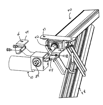
[0009] FIG. 1 is a perspective view of a drive for use with a screw jack
according to the present
invention;
[0010] FIG. 2 is second perspective view of the drive shown in FIG. 1;
[00111 FIG. 3 is a perspective view of the drive shown in FIG. I and a screw
drive stabilizing
jack;
[0012] FIG. 4 is a perspective view of the stabilizing jack shown in FIG. 3;
[0013] FIG. 5 is a perspective view of the drive shown in FIG. 1 and a screw
drive leveling
scissors jack;
[0014] FIG. 6 is a perspective view of the leveling scissors jack shown in
FIG. 3;
[0015] FIG. 7 is a plan view of the drive shown in FIG. 1, with a portion of
the gear housing
removed; and
[0016] FIG. 8 is a plan view of the drive gear mechanism shown in FIG. 1, with
a portion of
the gear housing removed.

-2-


CA 02549620 2006-06-06

Docket No. 116534.00154
DETAILED DESCRIPTION

[0017] FIG. 1 illustrates a jack power drive 10 for power operation of a screw
jack or camper
jack such as the stabilizing jack 40 shown in FIG. 4 or the leveling scissors
jack 50 shown in
FIG. 6. Drive 10 comprises a motor 20 connected to a gear assembly 22.
Preferably, gear
assembly 22 is a right angle gear assembly. The motor 20 includes a armature
shaft (not
shown) that extends into the right angle gear assembly 22. A worm gear 28 (see
FIG. 7) fits on
the end of the motor armature shaft.
100181 As shown in FIGS. 7 and 8, the right angle gear assembly 22 includes a
housing 25 that
is attached to the motor 20. A spur gear shaft (not numbered) is rotatably
supported within the
housing 25. The spur gear shaft has a centerline 23 that extends at a right
angle to a centerline
21 of the motor. A spur gear 27 is mounted on the spur gear shaft and engages
the motor worm
gear 28. One end of the spur gear shaft terminates in a hex head 24 and the
other end of the
spur gear shaft terminates in a hex socket 26. Hex socket 26 has a
complementary shape and
size to hex head 24.
100191 Drive 10 is intended to work with many types of screw jacks, i.e.,
jacks that use an
elongated threaded drive rod. One type of screw jack 40, a stabilizing jack,
is shown in FIGS.
3 and 4. Stabilizing jack 40 is operated by rotating an elongated threaded
screw (not shown) to
extend a leg 48. The elongated threaded screw terminates in a hex head 42. The
jack hex head
42 has a shape and size that is complementary to drive hex socket 26. Drive 10
is attached to
stabilizing jack 40 by fitting stabilizing jack hex head 42 into drive hex
socket 26. Brackets 44
are attached to drive 10 and stabilizing jack 40. Screws fit through mounting
holes 45 in
bracket 44 and mounting holes 47 in stabilizing jack 40 to attached the drive
10 to the
stabilizing jack 40 and to the recreational vehicle.
[0020] In operation, motor 20 is rotated in a first direction, which via the
right angle gear
assembly 22, rotates hex head 42 and the elongated threaded screw in a first
direction causing
leg 48 to extend from a recessed position (not shown) to an extended position.
Motor 20 is
operated until leg 48 contacts the ground and begins to pick up load. In a
preferred
embodiment, motor 20 is not large enough to continue to operate jack 40 once
load is picked up
by jack 40. To continue to operate jack 40 to pick up load and stabilize the
recreational
vehicle, drive hex head 24 is manually operated to continue to rotate the
right angle gear shaft

-3-


CA 02549620 2006-06-06

Docket No. 116534.00154
and the elongated jack threaded drive shaft to which drive 10 is attached by
drive hex socket
26. Any appropriate operator, such as a socket wrench, a box wrench, an
adjustable wrench,
crank handle, etc., can be used to engage drive hex head 24 and to manually
operate drive 10.
[00211 In a preferred embodiment, the teeth on spur gear 27 extend at an angle
29 to the spur
gear center line 23. Angle 29 is large enough to allow back driving of motor
20. This
facilitates the manual operation of the drive 10 without impeding the
operation of motor 20.
[0022] To lower the recreational vehicle and retract jack 40 to the recessed
position, the above
operation is reversed. Drive hex head 24 is manually operated to lower the
recreation vehicle
until the load on the jack 40 is reduced. Then, motor 20 is operated to fully
retract jack 40 to
the recessed position.
[0023] One second type of screw jack 50, a leveling scissors jack, is shown in
FIGS. 5 and 6.
Leveling scissors jack 50 is operated by rotating an elongated threaded screw
53 to raise a lift
platform 51. The elongated threaded screw 53 terminates in a hex head 52. The
jack hex head
52 has a shape and size that is complementary to drive hex socket 26. Drive 10
is attached to
leveling scissors jack 50 by fitting scissors jack hex head 52 into drive hex
socket 26. Brackets
54 are attached to drive 10 and leveling scissors jack 50. The leveling
scissors jack 50 is
attached to the recreational vehicle by bolting the lift platform 51 to the
recreational vehicle.
Apertures 57 in mounting brackets 54 fit about the ends 56 of a scissors jack
trunnion and the
mounting brackets 54 are secured to the right angle gear housing 25.
[0024] In operation, motor 20 is rotated in a first direction, which via the
right angle gear
assembly 22, rotates hex head 52 and the elongated threaded screw 53 in a
first direction
causing the leveling scissors jack 50 to extend from a retracted position (not
shown) to an
extended position. Motor 20 is operated until foot 58 contacts the ground and
the jack 50
begins to pick up load. In a preferred embodiment, motor 20 is not large
enough to continue to
operate jack 50 once load is picked up by jack 50. To continue to operate jack
50 to pick up
load and level the recreational vehicle, drive hex head 24 is manually
operated to continue to
rotate the right angle gear shaft and the elongated jack threaded drive shaft
to which drive 10 is
attached by drive hex socket 26. Any appropriate operator, such as a socket
wrench, a box
wrench, an adjustable wrench, crank handle, etc. can be used to engage drive
hex head 24 and
to manually operate drive 10.

-4-


CA 02549620 2006-06-06

Docket No. 116534.00154
[0025] To lower the recreational vehicle and retract jack 50 to the retracted
position, the above
operation is reversed. Drive hex head 24 is manually operated to lower the
recreation vehicle
until the load on the jack 50 is reduced. Then, motor 20 is operated to fully
retract jack 50 to
the retracted or recessed position.
[0026] In a further aspect, the present invention comprises a means for
rapidly translating the
jack 40, 50 between the retracted position to an extended no load position and
a means for
further translating the jack 40, 50 to an extended loaded position. The means
for rapidly
translating the jack to the extended no load position comprises the motor 20,
right angle gear
mechanism 22 and the jack threaded screw 53. The means for further translating
the jack to the
extended loaded position comprises the right angle gear assembly 22, the jack
threaded screw
53 and the manual operator attached to the drive hex head 24.

-5-

Representative Drawing
A single figure which represents the drawing illustrating the invention.
Administrative Status

For a clearer understanding of the status of the application/patent presented on this page, the site Disclaimer , as well as the definitions for Patent , Administrative Status , Maintenance Fee  and Payment History  should be consulted.

Administrative Status

Title Date
Forecasted Issue Date 2013-02-12
(22) Filed 2006-06-06
(41) Open to Public Inspection 2007-05-22
Examination Requested 2011-05-24
(45) Issued 2013-02-12

Abandonment History

There is no abandonment history.

Maintenance Fee

Last Payment of $624.00 was received on 2024-01-04


 Upcoming maintenance fee amounts

Description Date Amount
Next Payment if standard fee 2025-06-06 $624.00
Next Payment if small entity fee 2025-06-06 $253.00

Note : If the full payment has not been received on or before the date indicated, a further fee may be required which may be one of the following

  • the reinstatement fee;
  • the late payment fee; or
  • additional fee to reverse deemed expiry.

Patent fees are adjusted on the 1st of January every year. The amounts above are the current amounts if received by December 31 of the current year.
Please refer to the CIPO Patent Fees web page to see all current fee amounts.

Payment History

Fee Type Anniversary Year Due Date Amount Paid Paid Date
Registration of a document - section 124 $100.00 2006-06-06
Application Fee $400.00 2006-06-06
Maintenance Fee - Application - New Act 2 2008-06-06 $100.00 2008-05-23
Maintenance Fee - Application - New Act 3 2009-06-08 $100.00 2009-05-25
Maintenance Fee - Application - New Act 4 2010-06-07 $100.00 2010-05-04
Maintenance Fee - Application - New Act 5 2011-06-06 $200.00 2011-05-05
Request for Examination $800.00 2011-05-24
Maintenance Fee - Application - New Act 6 2012-06-06 $200.00 2012-03-26
Final Fee $300.00 2012-12-04
Maintenance Fee - Patent - New Act 7 2013-06-06 $200.00 2013-05-29
Maintenance Fee - Patent - New Act 8 2014-06-06 $200.00 2014-05-02
Maintenance Fee - Patent - New Act 9 2015-06-08 $200.00 2015-05-01
Maintenance Fee - Patent - New Act 10 2016-06-06 $250.00 2016-02-08
Maintenance Fee - Patent - New Act 11 2017-06-06 $250.00 2017-05-11
Maintenance Fee - Patent - New Act 12 2018-06-06 $250.00 2018-05-22
Maintenance Fee - Patent - New Act 13 2019-06-06 $250.00 2019-05-09
Maintenance Fee - Patent - New Act 14 2020-06-08 $250.00 2020-05-27
Maintenance Fee - Patent - New Act 15 2021-06-07 $459.00 2021-05-03
Maintenance Fee - Patent - New Act 16 2022-06-06 $458.08 2022-05-17
Maintenance Fee - Patent - New Act 17 2023-06-06 $473.65 2023-05-24
Maintenance Fee - Patent - New Act 18 2024-06-06 $624.00 2024-01-04
Owners on Record

Note: Records showing the ownership history in alphabetical order.

Current Owners on Record
NORCO INDUSTRIES, INC.
Past Owners on Record
GARCEAU, BERNARD F.
Past Owners that do not appear in the "Owners on Record" listing will appear in other documentation within the application.
Documents

To view selected files, please enter reCAPTCHA code :


To view images, click a link in the Document Description column. To download the documents, select one or more checkboxes in the first column and then click the "Download Selected in PDF format (Zip Archive)" or the "Download Selected as Single PDF" button.

List of published and non-published patent-specific documents on the CPD .

If you have any difficulty accessing content, you can call the Client Service Centre at 1-866-997-1936 or send them an e-mail at CIPO Client Service Centre.


Document
Description 
Date
(yyyy-mm-dd) 
Number of pages   Size of Image (KB) 
Maintenance Fee Payment 2020-05-27 1 33
Abstract 2006-06-06 1 9
Description 2006-06-06 5 215
Claims 2006-06-06 3 79
Representative Drawing 2007-05-01 1 18
Cover Page 2007-05-22 1 41
Claims 2011-05-24 6 198
Drawings 2012-04-17 8 177
Cover Page 2013-01-21 1 43
Representative Drawing 2013-02-05 1 19
Correspondence 2008-06-04 1 14
Correspondence 2008-06-04 1 18
Assignment 2006-06-06 7 201
Correspondence 2008-03-20 2 56
Prosecution Correspondence 2011-05-24 15 434
Prosecution-Amendment 2012-02-10 2 41
Prosecution-Amendment 2012-04-17 7 112
Correspondence 2012-12-04 1 46