Note: Descriptions are shown in the official language in which they were submitted.
CA 02549700 2006-06-07
PROCESS AND DEVICE FOR THE AUTOMATIC IDENTIFICATION OF
BREATHING TUBES
FIELD OF THE INVENTION
The present invention pertains to a process and a device for the automatic
identification of breathing tubes.
BACKGROUND OF THE INVENTION
Modern respiration systems are characterized by increasing complexity and
diversity
of possible uses. A plurality of components are frequently to be connected
before a
respiration system is ready for use. Different interfaces may be connected
with such
respiration systems, as a rule, with connection means, which may sometimes
imply an
increased risk for errors and possibly availability problems.
The connection of the breathing tube or the breathing tube system represents
an
essential connecting measure during the configuration of breathing systems.
The breathing
tube and the breathing tube system shall hereinafter be considered to be
equivalent in
connection with the present invention, because the particular fluidic design
of the tubes and
systems is not critical.
It is known, in principle, that the risk for misconnections can be reduced in
medical
engineering systems by connecting identification means to the individual
components (DE
201 13 789 U1).
However, this has not hitherto been used in the area of breathing systems and
breathing tubes because it was assumed that misconnections can be ruled out by
the
mechanical design of the connectors. However, the standards and types of
breathing tubes
that have meanwhile become established have led to a diversity that cannot be
systematized
exclusively by certain types of connectors. Each standard type of connector is
now designed
such that it can be connected to different breathing tube systems, which are
intended for very
special modes of respiration. However, this makes necessary the accurate
identification of the
type of the breathing tube system connected.
CA 02549700 2006-06-07
Various parameters, which are necessary for the optimal functionality of the
device
and are determined by the nature of the tube, have hitherto been measured for
this purpose by
the system and entered by the user in the software of the device. These
include, for example,
tube volumes or modes of heating.
SUMMARY OF THE INVENTION
The object of the present invention is to propose a possibility of reducing
the risk for
misconnections in breathing systems and of improving the ease of use without
having to
resort to a substantially increased effort.
According to the invention, a process is provided for the automatic
identification of
the type of a breathing tube. A memory element is connected to the breathing
tube, on which
data identifying the breathing tube are stored. The memory element is read by
means of a
reading unit which is part of a respirator (ventilator), when the breathing
tube is brought into
the vicinity of the respirator.
According to another aspect of the invention, a device is provided for the
automatic
recognition of the type of a breathing tube according to the process. At least
one breathing
tube is connected to a respirator with a memory element, on which data
identifying the
breathing tube are stored, is rigidly connected to the breathing tube. The
respirator has means
that make possible the reading of the data from the memory element when the
breathing tube
is located in the vicinity of the respirator.
The present invention is based essentially on the fact that when a breathing
tube is
connected to a respirator, connection elements will interact with one another,
which require
the relatively accurate positioning of an end of the breathing tube in
relation to the respirator.
This positioning is used to position a memory element, which is connected to
the breathing
tube and can be read by a reading unit, which is connected to the respirator.
Data that make it
possible to identify the type of the breathing tube are stored in the memory
element.
The present invention consists of a process for the automatic identification
of the type
of a breathing tube, in which a memory element, which is connected to the
breathing tube and
on which data identifying the breathing tube are stored, is read by a reading
unit that is part of
2
CA 02549700 2006-06-07
the respirator, when the breathing tube is brought into the vicinity of the
respirator.
The type of the breathing tube is advantageously identified by reading the
memory
element, which is connected to the breathing tube and on which data
identifying the breathing
tube are stored when the breathing tube is connected to the respirator.
Misinterpretation due
to the reading of other data storage media, which are located in the vicinity
of the reading
unit, are avoided as a result.
An alarm is advantageously triggered when a breathing tube that is not
suitable for an
intended mode of respiration is identified or a mode of respiration that does
not fit the
identified breathing tube is set on the respirator.
At the same time, a check can be performed to determine whether the breathing
tube is
connected correctly to the respirator, and an alarm is triggered when the
breathing tube is not
connected correctly to the respirator. Correct connection is defined in the
sense of the present
invention as the use of an intended breathing tube and the arrangement thereof
in a functional
manner. Incorrect positioning can be extensively ruled out as a result.
It is especially advantageous if the reading unit is designed as a writing and
reading
unit and additional data are stored in the memory element connected to the
breathing tube
while the breathing tube is being connected to the respirator. Possible
additional data may be,
for example, respiration parameters, patient data, accounting data, therapy
data and/or
diagnostic data as well as data that log the use of the breathing tube. These
include data about
cleaning and sterilization steps.
As a result, possibilities advantageously arise for keeping these additional
data
available for a later use. For example, after the breathing tube has been
connected to a
respirator, stored respiration parameters can be read and these respiration
parameters can be
taken over by the connected respirator, preferably after release by authorized
personnel. The
data may just as well be processed and passed on to a central system of the
hospital's logistic
unit or a patient management system.
One advantage of the present invention is that breathing tubes are frequently
intended
to remain in the vicinity of the patient for a rather long time in modern
respiration systems,
whereas the respirators proper are replaced more frequently or are connected
to the patient for
a short time only. Due to the connection, according to the present invention,
of the data
3
CA 02549700 2006-06-07
storage means with a breathing tube that remains in the vicinity of the
patient for a longer
period of time, loss of this data storage medium while the breathing tube is
located in the
vicinity of the patient is nearly ruled out. The breathing tube thus assumes
the function of an
always available, patient-related data storage unit in a manner according to
the present
invention. The connection of a data storage means with a breathing tube, which
remains in
the vicinity of the patient for a rather long time, is automatically linked
with the fact that no
additional actions are necessary for making available the data storage unit
and this data on the
data storage unit can never be forgotten.
The means for reading the data from the memory element are advantageously
integrated in a pneumatic interface at the respirator and are designed such
that reading takes
place when a breathing tube compatible with this interface is connected. The
connection
means that can be connected to one another or the parts of the pneumatic
interface that can be
connected to one another are connected to the data transmission means at least
in a
sufficiently dimensionally stable manner in such a way that ensures that in
case of the
components connected to one another, namely, the breathing tube and the
respirator, the data
transmission means are arranged at least such that data transmission can take
place. This
principle of connecting data transmission means to position-determining
connection means
that can be connected to one another is to be considered to be integrated in
the sense of the
present invention.
Due to the integration of the data transmission means into the pneumatic
interface,
which must be connected for the operation of the respiration system anyway, it
is achieved,
furthermore, that no additional actions are necessary for connecting the data
storage means at
the breathing tube to a writing or reading unit, which is located at the
respirator, which is
highly advantageous for operation under pressure of time.
It is especially advantageous if the data transmission takes place in a
contactless
manner, which is especially advantageous when oxygen is handled.
In an advantageous embodiment of a system according to the present invention,
the
data storage means and/or the data transmission means are designed such that
they are
suitable for the storage and the transmission of additional information via
breathing tubes that
4
CA 02549700 2006-06-07
can be connected to the respirator. This information may contain, for example,
data on
manufacture, storage and shelf life.
In another advantageous embodiment, the data storage means and/or data
transmission
means are designed such that they are suitable for the storage and
transmission of patient data,
therapy data andlor diagnostic data. The data storage means can thus partially
assume the
function of an electronic patient file and make necessary data automatically
available to the
particular attending physician.
It proved to be particularly advantageous if the data transmission means
andlor data
storage means are part of an RFID system. The data storage means, in
particular, comprises
at least one memory element in the form of an RFID tag, which is rigidly
connected to the
breathing tube.
To prevent unauthorized access to the stored data, it is advantageous to code
the data
and to make them available only during reading by a corresponding decoding
method. It is
necessary for this that means for coding and decoding the transmitted andlor
stored data be
contained. These means may comprise, for example, suitable software
components, which
are integrated in a control unit of the respirator.
Furthermore, it is advantageous if means are contained that make it possible
to
manually store information that prevents the further use of the breathing tube
connected to the
respirator. These include, for example, a manual switch, which ensures the
transmission and
storage of a blocking code on actuation. If this code is subsequently read,
the respirator will
demand the replacement of the blocked breathing tube. This may be useful in
case of unclear
risks for infection or obvious damage.
The present invention will be explained in greater detail on the basis of an
exemplary
embodiment. The various features of novelty which characterize the invention
are pointed out
with particularity in the claims annexed to and forming a part of this
disclosure. For a better
understanding of the invention, its operating advantages and specific objects
attained by its
uses, reference is made to the accompanying drawings and descriptive matter in
which
preferred embodiments of the invention are illustrated.
CA 02549700 2006-06-07
BRIEF DESCRIPTION OF THE DRAWINGS
In the drawings:
Figure 1 is a schematic view showing a device for carrying out the process
according
to the present invention in the form of a respiration system;
Figure 2 is a block diagram of such a respiration system;
Figure 3 is a schematic view showing a respiration system according to the
present
invention in the area of the pneumatic interface, i.e., the connection of the
breathing tube to
the respirator; and
Figure 4 is a schematic view showing the general design of a respiration
system for
carrying out the process according to the present invention
6
CA 02549700 2006-06-07
DESCRIPTION OF THE PREFERRED EMBODIMENTS
Referring to the drawings in particular, a respiration system equipped
according to the
present invention comprises a breathing tube or a breathing tube system with a
memory
element. Furthermore, respirators are comprised, which have a reading and
writing unit,
which can communicate with the memory element when the breathing tube system
is
connected. Compared to conventional respiration systems, this offers numerous
advantages,
which will be described below.
There are a plurality of types of breathing tubes. Thus, there are disposable
tubes and
tubes that can be used several times, different tube lengths, different
diameters, double tube
systems, coaxial tubes, tubes with a semipermeable membrane for the passage of
moisture,
tubes heated by electric heating wires, and tubes with temperature sensors and
flow-
measuring units.
Many patients undergo mechanical respiration within the framework of their
medical
care, and different respiration systems may be used one after another in the
course of the
treatment.
Each combination of a given type of tube with a certain respirator requires
defined
respiration parameters and rules out other respiration parameters. In
addition, respiration
parameters must be selected according to therapeutic criteria. The essential
parameters are
the form of respiration, the oxygen content, the respiration rate, optionally
the stroke volume,
the maximum volume, the respiration pressure as well as a maximum allowable
pressure.
Currently existing respiration systems make it necessary to set the patient's
individual
respiration parameters manually by the user on each respirator in order to
ensure optimal
treatment.
The optimal setting of the parameters depends on a large number of individual
factors
of the patient, which describe the respiration demand. The optimal setting of
the respiration
parameters therefore requires a considerable amount of time on the part of the
attending staff.
After the beginning of the medical care, a patient usually passes through
different
stations. These may be an ambulance/helicopter, outpatient department,
induction, OP,
termination, intensive care unit and various transportations inside and
outside the hospital. If
7
CA 02549700 2006-06-07
respiration is required for a patient, the parameters must be set anew by the
staff for each
respiration system along this chain in conventional systems.
The effort described decreases and the risk for error is substantially
diminished due to
the use of a respiration system equipped according to the present invention.
The type of the
connected breathing tube is automatically identified.
Respiration parameters may be stored as data sets in the memory element, which
is
integrated in the breathing tube system. The breathing tube system remains at
the patient
when the clinical area or the respirator is changed. After connecting another
respirator, these
data are available for the newly connected respirator, which makes possible
the automatic or
semi-automatic setting of the necessary respiration parameters. Furthermore,
it is possible to
store data on forbidden parameters that must not be set by any means when the
particular type
of tube is used, which markedly reduces the risk for the incorrect supply of
the patient. It is
thus possible to embody at least an alarm device, which triggers an alarm when
a breathing
tube that is not suitable for an intended mode of respiration is identified or
if a mode of
respiration that does not fit the identified breathing tube is set on the
respirator.
In addition or as an alternative to respiration parameters, data on a
performed
treatment can be stored in the memory element and later read for accounting
purposes. For
example, the minutes of respiration performed can thus be logged.
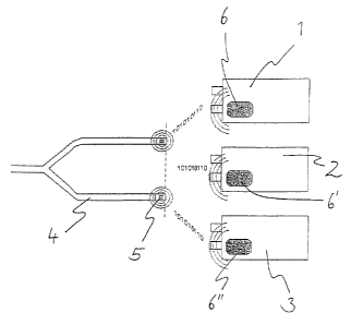
Figure 1 shows a device for carrying out the process according to the present
invention
in the form of a respiration system. The exemplary embodiment pertains to a
system
comprising at least two respirators, and three respirators 1, 2, 3 in this
case, and at least one
breathing tube system 4, wherein the respirators are able to store and read
individual
respiration parameters of the patient on a memory element 5 on the breathing
tube system 4 in
a contactless manner when one of the respirators l, 2, 3 is connected to the
breathing tube
system 4. In addition, data that make it possible to identify the type of the
connected
breathing tube system 4 are stored on the memory element 5. The respirators
are an
emergency respirator 1, an intensive care respirator 2 and an anesthesia
respirator 3, as they
may be used at a patient at different points in time.
8
CA 02549700 2006-06-07
The connection is established such that respiration parameters of one
respirator are
stored with a respective writing and reading unit 6, 6', 6" on the memory
element S of the
breathing tube system 4 and these parameters are read by the other respirators
from the
memory element 5 in the breathing tube system 4 and can thus be set
automatically or semi-
automatically by the individual respirators. It is thus achieved that the
respiration parameters
set on the first respirator are also set on another respirator after the
breathing tube system is
plugged into that other respirator.
Basic requirements on breathing tubes are described in EN12342. This standard
also
defines the mechanical interface to the respiration system, which is usually
designed by
means of a conical male connector at the respiration system and a female
connector at the
breathing tube. The common standards of 22 mm, 1 S mm and 10 mm diameter exist
for the
connectors. This connector system represents a pneumatic interface in the
sense of the
present invention, which ensures in the connected state the accurate
positioning of the shaped
parts that are in contact with one another.
Each respirator automatically stores all settings of the respiration
parameters on the
memory element in the breathing tube system. After the tube is plugged into
another
respirator, the latter will automatically read the particular data last stored
on the memory
element and sets these data on the new respirator. This may possibly take
place after polling
and confirmation on the display screen. If something has in turn changed in
the settings in
this respirator, this is automatically stored in the memory element and
optionally transmitted
to another respirator connected at a later point in time. In order not to
change the process
within the clinical procedure, a passive, cableless memory element is used,
which can be read
without additional working steps.
The advantage of the solution for the user is the marked simplification of the
clinical
processes and consequently the cost reduction due to fewer and shorter working
steps.
The complicated manual individual programming of every individual respirator
for a
particular patient is eliminated and replaced by a brief polling. After a
change in the clinical
area or the respiration system, optimal respiration parameters can be set
within a few seconds,
whereas substantially more time is necessary for this in conventional systems.
9
CA 02549700 2006-06-07
Furthermore, optimal treatment of the patient is ensured in all areas, because
errors in
operating the system are extensively ruled out. A stable and lastingly
optimized state of
respiration can be achieved due to the continued use of optimized respiration
parameters on
different devices.
The communication between the breathing tube system and the particular
respirator
takes place via a contactless data connection in the exemplary embodiment.
The memory element is embodied by an RFID chip, a so-called tag, in the tube
nozzle.
This tag is applied either by bonding or injection. It is arranged
geometrically in the tube
nozzle such that it can be read and written on by a writing and reading unit
in the respirator
via an antenna when the breathing tube system is connected to the respirator.
The RFID embodies an inductive process, in which an antenna on a tag is
excited with
a defined frequency. A small chip on the RFID tag thereupon sends back the
stored
information. There are a large number of different RFID standards and RFID
tags with
different functionalities.
Figure 2 shows a block diagram of a respiration system according to the
present
invention. The respirator 1 itself contains a control unit ?, which controls
all the processes
occurring during the operation of the device. Data necessary for this can be
entered via an
operating unit 8. The breathing tube system 4 that can be connected to the
respirator 1 has an
RFID tag as a memory element 5. A writing and reading unit 6 in the respirator
1 can
communicate with this RFID tag, which is embodied via a corresponding antenna
9. The
writing and reading unit 6 can also pass on the data read from the RFID tag to
the control unit
7. If the RFID tag contains data on respiration parameters, these can replace
entry via the
operating unit. The respiration parameters are displayed, instead, on the
operating unit 8 and
taken over by the user as a setting by a release.
Various data, which identify the breathing tube system, are already written on
the
RFID tag in the state in which the breathing tube system is supplied. These
data contain
information in the form of an identification number, a manufacturer code and
make it possible
to read the date of manufacture and other specific data. Furthermore,
respiration parameters,
which must not be set with the breathing tube system, are stored. For example,
large stroke
CA 02549700 2006-06-07
volumes, which would be typical for the respiration of adult patients, can
thus be prevented
from being set on the respirator when a breathing tube system is used for
newborns.
When the respirator recognizes the RFID tag, this means that a tube is
connected.
Respiration parameters that may already be stored on the RFID tag are
subsequently
compared with the respiration parameters set in the software of the device and
stored on the
RFID tag by the user in case of a change. Conversely, the stored respiration
parameters are
read from the RFID tag by means of the writing and reading unit after the
breathing tube
system is connected to a respirator and are used by an associated control
device to
automatically or semi-automatically, after release, set the mode of
respiration, which is
usually performed by a software of the device.
Figure 3 shows a respiration system according to the present invention in the
area of
the pneumatic interface. A breathing gas connection with a variable-angle male
connector 10
is arranged at a respirator 1. A breathing tube system 4 is connected to this
connector 10 by
connecting a sealing nozzle 11 as a female connector with the male connector
10. An RFID
tag, not visible in this figure, is connected to an antenna 12. In this
example, a coil is
embedded as an antenna 12 of the tag by injection molding in the nozzle 11
such that its
windings are directed at right angles to the axis of the tube connection. An
antenna 9 of a
device-side writing and reading unit is arranged in this variant at right
angles to the axis of the
part of the breathing gas connection 13 which is rigidly connected to the
respirator 1. It is
achieved in this manner that the fields that are formed around the antennas 9,
12 have a
parallel component each in relation to the receiving antenna in all positions
of the variable-
angle male connector 10 (except a connector bent at right angles), which
ensures a sufficient
inductive coupling for carrying out the present invention.
Figure 4 shows the general design of a respiration system for carrying out the
process
according to the present invention. It is a respiration system that comprises
at least one
breathing tube system 44 and a respirator 41, which can be connected to one
another via
positioning-determining connection means 410, 411, wherein the breathing tube
system 44
contains at least one memory element 45, which can be read via an interface
46, which is
mechanically connected to the position-determining connection means 410, 411.
While specific embodiments of the invention have been shown and described in
detail
11
CA 02549700 2006-06-07
to illustrate the application of the principles of the invention, it will be
understood that the
invention may be embodied otherwise without departing from such principles.
12