Note: Descriptions are shown in the official language in which they were submitted.
CA 02550029 2011-10-18
CONFINING POSITIVE AND NEGATIVE IONS WITH FAST OSCILLATING
ELECTRIC POTENTIALS
Field of Invention
100011 The present invention relates to mass spectrometry and more
specifically to
confining positive and negative ions with fast oscillating electric
potentials.
BACKGROUND
100021 The present invention relates to mass spectrometry.
100031 A mass spectrometer analyzes masses of sample particles, such as
atoms and
molecules, and typically includes an ion source, one or more mass analyzers
and one or more
detectors. In the ion source, the sample particles are ionized. The sample
particles can be
ionized with a variety of techniques that use, for example, chemical
reactions, electrostatic
forces, laser beams, electron beams or other particle beams. The ions are
transported to one
or more mass analyzers that separate the ions based on their mass-to-charge
ratios. The
separation can be temporal, e.g., in a time-of-flight analyzer, spatial e.g.,
in a magnetic sector
analyzer, or in a frequency space, e.g., in ion cyclotron resonance ("ICR")
cells. The ions can
also be separated according to their path or trajectory stability in a
multipole ion trap or ion
guide. The separated ions are detected by one or more detectors that provide
data to
construct a mass spectrum of the sample particles.
100041 In the mass spectrometer, ions are guided, trapped or analyzed
using magnetic
fields or electric potentials, or a combination of magnetic fields and
electric potentials. For
example, magnetic fields are used in ICR cells, and multipole electric
potentials are used in
multipole traps such as three-dimensional ("3D") quadrupole ion traps or two-
dimensional
("2D") quadrupole traps.
100051 For example, linear 2D multipole traps can include multipole
electrode
assemblies, such as quadrupole, hexapole, octapole or greater electrode
assemblies that
include four, six, eight or more rod electrodes, respectively. The rod
electrodes are arranged
in the assembly about an axis to define a channel in which the ions are
confined in radial
directions by a 2D multipole potential that is generated by applying radio
frequency ("RF")
voltages to the rod electrodes. The ions are traditionally confined axially,
in the direction of
the channel's axis, by DC biases applied to the rod electrodes or other
electrodes such as
1
CA 02550029 2006-06-15
WO 2005/074004 PCT/US2005/001846
plate lens electrodes in the trap. In a portion of the channel defined by the
rod electrodes, the
DC biases can generate electrostatic potentials that axially confine either
positive ions or
negative ions, but cannot simultaneously confine both. Additional AC voltages
can be
applied to the rod electrodes to excite, eject, or activate some of the
trapped ions.
[0006] In MS/MS experiments, selected precursor ions (also called parent
ions) are
first isolated or selected, and next reacted or activated to induce
fragmentation to produce
product ions (also called daughter ions). Mass spectra of the product ions can
be measured to
determine structural components of the precursor ions. Typically, the
precursor ions are
fragmented by collision activated dissociation ("CAD") in which the precursor
ions are
kinetically excited by electric fields in an ion trap that also includes a low
pressure inert gas.
The excited precursor ions collide with molecules of the inert gas and may
fragment into
product ions due to the collisions.
[0007] Product ions can also be produced by electron capture dissociation
("ECD") or
ion-ion interactions. In ECD, low energy electrons are captured by multiply
charged positive
precursor ions, which then may undergo fragmentation due to the electron
capture. To induce
ECD processes in ICR cells, the precursor ions and the electrons are radially
confined by
large magnetic fields, typically from about three to about nine Tesla.
Axially, the positive '
precursor ions and the electrons are confined by electrostatic potentials in
adjacent regions.
Near the border of the adjacent regions, trajectories of the precursor ions
and the electrons
may overlap and ECD may take place. Alternatively, the trapped precursor ions
may be
exposed to a flux of low energy electrons.
[0008] Multipole ion traps typically use RF multipole potentials to
radially confine
ions. An electron's mass-to-charge ratio is one hundred thousand to one
million times
smaller than mass-to-charge ratios of typical precursor ions. Conventional
multipole traps,
however, can simultaneously confine only particles whose mass-to-charge ratios
do not differ
more than about a few hundred times. It has been suggested that ECD can be
performed in a
multipole trap if additional magnetic fields are used to trap the electrons or
a large flux of
electrons is introduced.
[0009] Ion-ion interactions have been used to generate product ions in 3D
quadrupole
traps, where an oscillating 3D quadrupole potential can simultaneously confine
positive and
negative ions in a central volume, and no electrostatic potentials are
required to provide axial
confinement.
2
CA 02550029 2006-06-15
WO 2005/074004 PCT/US2005/001846
SUMMARY
[0010] In a two-dimensional (2D) multipole ion trap or ion guide that
defines an
internal volume, ions are confined by oscillating electric potentials in both
radial and axial
directions. In general, in one aspect, the invention provides techniques for
trapping or
guiding ions. Ions are introduced into an ion trap or ion guide. The ion trap
or ion guide
includes a first set of electrodes and a second set of electrodes. The first
and second sets of
electrodes are arranged to define an ion channel to trap or guide the
introduced ions. Periodic
voltages are applied to electrodes in the first set of electrodes to generate
a first oscillating
electric potential that confines the ions in the ion channel in at least a
first dimension, and
periodic voltages are applied to electrodes in the second set of electrodes to
generate a second
oscillating electric potential that confines the ions in the ion channel in at
least a second
dimension.
[0011] Particular implementations can include one or more of the
following features.
The application of periodic voltages to the first and second sets of
electrodes can provide ion
confinement in three dimensions. The first oscillating electric potential can
confine the ions
radially. The second electricpotential can confine the ions axially. The first
and second sets
of electrodes can comprise elements, and have at least one element in common.
Introducing
ions can include introducing positive ions and negative ions into the ion trap
or ion guide.
The ion trap or ion guide can include a first end and a second end, and the
positive and
negative ions can be introduced at the first end and the second end,
respectively. The ion trap
or ion guide can include two or more sections, and one or more DC biases can
be applied to
one or more of the sections of the ion trap or ion guide to confine the
positive or the negative
ions into one or more trapping regions. Applying periodic voltages to
electrodes in the first
set of electrodes can include applying periodic voltages with a first
frequency, and applying
periodic voltages to electrodes in the second set of electrodes can include
applying periodic
voltages with a second frequency that is different from the first frequency.
The first and
second frequencies can have a ratio that is about an integer number or a ratio
of integer
numbers. The first and second frequencies have a ratio of about two. The first
and second
oscillating electric potentials can have different spatial distributions. The
ion channel can
have an axis of symmetry, and the first oscillating electric potential can
define substantially
zero electric field on at least a portion of the axis of the ion channel, and
the second
oscillating electric potential can define substantially non-zero electric
field on the same
portion of the axis of the ion channel. The first oscillating potential can
include an oscillating
quadrupole, hexapole or larger multipole potential. The second oscillating
potential can
3
CA 02550029 2006-06-15
WO 2005/074004
PCT/US2005/001846
include an oscillating local dipole potential. The first and second
oscillating electric
potentials can define a pseudopotential for each particular mass and charge of
the introduced
ions such that each of the defined pseudopotentials specifies a corresponding
potential barrier
along the ion channel. The first set of electrodes can include a plurality of
rod electrodes.
The second set of electrodes can include a plurality of rod electrodes and/or
can include one
or more plate ion lens electrodes. The second set of electrodes can include a
first plate ion
lens electrode at a first end of the ion channel and a second plate ion lens
electrode at a
second end of the ion channel.
[0012] In general, in another aspect, the invention provides an
apparatus. The
apparatus includes a first set and a second set of electrodes and a
controller. The first and
second sets of electrodes are arranged to define an ion channel to trap or
guide ions. The
controller is configured to apply periodic voltages to electrodes in the first
set and the second
set to establish a first oscillating electric potential and a second
oscillating electric potential,
wherein the first and second oscillating electric potentials have different
spatial distributions
and confine ions in the ion channel in radial and axial directions,
respectively.
[0013] Particular implementations can include one or more of the
following features.
The controller can be configured to confine simultaneously positive and
negative ions in the
ion channel in both radial and axial directions. The controller can be
configured to apply
periodic voltages to electrodes in the first set of electrodes with a first
frequency, and to
electrodes in the second set of electrodes with a second frequency that is
different from the
first frequency. The first and second frequencies can have a ratio that is
about an integer
number or a ratio of integer numbers. The first set of electrodes can include
a plurality of rod
electrodes. The second set of electrodes can include a plurality of rod
electrodes or one or
more plate ion lens electrodes. The second set of electrodes can include a
first plate ion lens
electrode at a first end of the ion channel and a second plate ion lens
electrode at a second
end of the ion channel.
[0014] The invention can be implemented to provide one or more of the
following
advantages. Positive and negative ions can be simultaneously confined in an
internal volume
or trapping region defined by electrode structures and associated applied
voltages in a 2D
multipole ion trap. Due to the simultaneous confinement in the same volume,
product ions
can be generated by ion-ion interactions. The 2D multipole ion trap can trap
substantially
more (typically, thirty to one hundred fold more) positive and negative ions
than a 3D
quadrupole trap. Thus, the 2D multipole trap can provide more product ions for
a later
analysis, which can be performed with larger signal-to-noise ratios, and low
abundance
4
CA 02550029 2006-06-15
WO 2005/074004 PCT/US2005/001846
product ions may also be detected. The positive and negative ions can be more
conveniently
introduced in a 2D multipole ion trap than into a 3D quadrupole trap. For
example, the
positive ions can be introduced at one end of a linear 2D multipole trap and
the negative ions
can be introduced at the other end. The positive ions can be precursor ions
and the negative
ions can be reagent ions that may induce charge transfer to or from the
precursor ions.
Alternatively, the positive ions can be reagent ions and the negative ions can
be precursor
ions. Alternatively, negative reagent ions may abstract charged species,
typically one or
more protons, from the precursor ion. The charge transfer can reduce a
multiple charge of the
precursor ion, invert the charge polarity of the precursor ion, or induce a
fragmentation of the
precursor ion. For precursor ions such as phosphopeptide ions, the charge
transfer reaction
may precipitate fragmentation that results in product ion spectra that are
more informative
than the product ion spectra of the same species produced with CAD alone. Such
charge
transfer may induce fragmentation or simply charge reduction of ions other
than the precursor
ions, such as fragmentation or charge reduction of the product ions produced
by prior charge
transfer reactions. In a linear 2D quadrupole trap or other 2D multipole rod
assembly,
precursor ions and reagent ions having opposite sign of charge can be trapped
in the same
volume both radially and axially by a superposition of RF electric potentials,
without large
magnetic fields. A segmented linear trap can initially store precursor ions
and reagent ions in
separate segments and induce fragmentation later by allowing the precursor
ions and the
reagent ions to interact in the same segment or segments. Before allowing
their interaction,
the precursor ions or the reagent ions may be manipulated in the separate
segments using
conventional methods, such as selecting the precursor or reagent ions by
established methods
of isolation. The ion-ion interactions can be stopped at any time by re-
segregating the
positive and negative ion populations. In a channel where an ion population
includes positive
ions, negative ions or both, and the ions are radially confined by electric
fields defined by a
primary RF potential, a secondary RF electric potential can define electric
fields that
selectively confine ions of the population in the axial direction of the
channel based on the
mass and charge of an ion, but independent of the sign of the ion's charge.
Thus, axial
confinement can be used as a valve or a gate that can be opened or closed to
allow or block
the passage of ions in the axial direction. Axial confinement can be provided
by an electric
potential that is generated by secondary RF voltages applied to lens end plate
electrodes. In
an assembly with two or more axial segments, the ions can be axially confined
by applying
different combination of RF voltages to multipole rods in different segments
of the assembly.
One or more of the segments of the assembly, can be implemented by separate 2D
multipole
CA 02550029 2006-06-15
WO 2005/074004
PCT/US2005/001846
traps. Axial confinement may also be achieved by applying secondary RF
voltages to
auxiliary electrodes located around, adjacent or in between the multipole rod
electrodes of the
multipole ion trap. Because linear ion traps are readily adapted to other mass
spectrometers,
after performing ion-ion reaction experiments in the linear ion traps, the
product ions can be
easily transported for analysis to different mass analyzers, such as TOF,
FTICR or different
RF ion trap mass spectrometers. Thus ion-ion experiments can use a wide range
of
instruments, not just 3D quadrupole ion traps.
[0015] The details of one or more embodiments of the invention are set
forth in the
accompanying drawings and the description below. Unless otherwise noted, the
verbs
"include" and "comprise" are used in an open-ended sense - that is, to
indicate that the
"included" or "comprised" subject matter is a part or component of a larger
aggregate or
group, without excluding the presence of other parts or components of the
aggregate or
group. The terms "front", "center", and "back," are used to denote parts of an
apparatus, such
as a multipole ion trap or equivalent thereof, in schematic illustrations
without particular
reference to the actual locations of the parts of the apparatus in any
absolute sense, such as
when the apparatus is inverted or rotated. Other features and advantages of
the invention will
become apparert from the description, the drawings and the claims.
BRIEF DESCRIPTION OF THE DRAWINGS
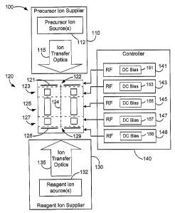
[0016] FIG. 1 is a schematic diagram illustrating apparatus for mass
spectrometry
according to one aspect of the invention.
[0017] FIGS. 2A-2D are schematic diagrams illustrating axial confinement
of ions
with oscillating electric potentials.
[0018] FIG. 3 is a schematic flow diagram illustrating a method for mass
spectrometry according to one aspect of the invention.
[0019] FIG. 4 is a schematic flow diagram illustrating a method for
inducing ion-ion
reactions.
[0020] FIGS. 5A-5F are schematic diagrams illustrating an exemplary
implementation of inducing ion-ion reactions in a multipole trap.
[0021] FIG. 6 is a schematic diagram illustrating an alternative
embodiment of
apparatus to induce ion-ion interactions.
[0022] FIG. 7 is a schematic diagram illustrating yet another alternative
embodiment
of apparatus to induce ion-ion interactions.
6
CA 02550029 2006-06-15
WO 2005/074004 PCT/US2005/001846
DETAILED DESCRIPTION
[0023] FIG. 1 illustrates a mass spectrometry system 100 configured to
operate
according to one aspect of the invention. The system 100 includes a precursor
ion supplier
110, a 2D multipole ion trap 120, a reagent ion supplier 130 and a controller
140. The
precursor ion supplier 110 generates ions that include precursor ions. The
ions generated by
the precursor ion supplier 110 are injected into the 2D multipole ion trap
120. The reagent
ion supplier 130 generates ions that include reagent ions. The ions generated
by the reagent
ion supplier 130 are also injected into the 2D multipole ion trap 120. The 2D
multipole ion
trap 120 defines a channel in which the precursor ions and the reagent ions
can be confined
both radially and axially by oscillating electric potentials generated by
periodic voltages that
are applied to different electrodes in the ion trap 120 by the controller 140.
[0024] The precursor ion supplier 110 includes one or more precursor ion
sources 112
to generate precursor ions from sample molecules, such as large biological
molecules, and
ion transfer optics 115 to guide the generated ions from the precursor ion
sources 112 to the
ion trap 120. Precursor ions can be generated using electrospray ionization
("ESI"),
thermospray ionization, field, plasma or laser desorption, chemical ionization
or any other
technique to generate precursor ions. The precursor ions can be positive or
negative ions and
can have single or multiple charges. For example, ESI techniques produce
multiply charged
ions from large molecules that have multiple ionizable sites.
[0025] The reagent ion supplier 130 includes one or more reagent ion
sources 132 to
generate reagent ions from sample molecules, and ion transfer optics 135 to
guide the
generated ions from the reagent ion sources 132 to the ion trap 120. Upon
interaction, the
reagent ions may induce charge transfer from the reagent ions to other ions,
such as the
precursor ions generated by the precursor ion supplier 110. The reagent ions
can induce
proton transfer or electron transfer to or from the precursor ions. For
positive precursor ions,
the reagent ions can include anions derived from perfluorodimethylcyclohexane
(PDCH) or
SF6. For negative precursor ions, the reagent ions can be positive ions, such
as Xenon ions.
The choice of the particular reagent ions can depend on the precursor ions
and/or parameters
of the ion trap.
[0026] For positive precursor ions, the reagent ion sources 132 generate
negative
reagent ions using chemical ionization, ESI, thermospray, particle
bombardment, field,
plasma or laser desorption. For example in chemical ionization, negative
reagent ions are
generated by associative or dissociative processes in a chemical plasma that
includes neutral,
positively and negatively charged particles, such as ions or electrons. In the
chemical
7
CA 02550029 2006-06-15
WO 2005/074004 PCT/US2005/001846
plasma, low energy electrons may be captured by neutral particles to form a
negative ion.
The negative ion may be stable or may fragment into product ions that include
negative ions.
The negative reagent ions can be extracted from the chemical plasma, for
example, by
electrostatic fields. In alternative implementations, the reagent ion sources
132 generate the
reagent ions using other techniques. For example, positive or negative ions
can be generated
by selection of the appropriate voltage and the use of ESI.
[0027] The ion transfer optics 115 and 135 transport the ions generated
by the
precursor ion sources 112 and the reagent sources 132, respectively, to the
multipole ion trap
120. The ion transfer optics 115 or 135 can include one or more 2D multipole
rod assemblies
such as quadrupole or octapole rod assemblies to confine the transported ions
radially in a
channel. The ions can be transported between different rod assemblies by inter-
multipole
lenses. The ion transfer optics 115 or 135 can be configured to transport only
positive or
negative ions or to select ions with particular ranges of mass-to-charge
ratios. The ion
transfer optics 115 or 135 can include lenses, ion tunnels, plates or rods to
accelerate or
decelerate the transported ions. Optionally, the ion transfer optics 115 or
135 can include ion
traps to temporarily store the transported ions.
[0028] The multipole ion trap 120 includes a front plate lens 121, a back
plate lens
128 and one or more sections between the lenses 121 and 128. In the
implementation shown
in FIG. 1, the ion trap 120 includes a front section 123, a center section 125
and a back
section 127. The front lens 121 defines a front aperture 122 to receive the
ions transported by
the ion transfer optics 115 from the precursor ion sources 112, and the back
lens 128 defines
a back aperture 129 to receive the ions transported by the ion transfer optics
135 from the
reagent ion sources 132. Each of the sections 123, 125 and 127 includes a
corresponding 2D
multipole rod assembly, such as a quadrupole rod assembly including four
quadrupole rod
electrodes. Each of the multipole rod assemblies is operable to confine ions
in at least one
dimension in a channel about an axis 124 of the ion trap 120. In this channel,
ions can be
radially and axially confined in one or more of the sections 123, 125, 127 by
oscillating
electric potentials generated by the voltages applied to the multipole rod
electrodes and the
lenses 121 and 128 of the ion trap 120. In alternative implementations, one or
more of the
sections 123, 125 and 127 can be implemented by separate 2D ion traps. In the
implementation depicted in Figure 1, a first set of electrodes (which may
include electrodes
corresponding to one or more from the front section 123, center section 125
and back section
127) is operable to confine ions in at least a first dimension in the ion
channel, to trap or
guide the introduced ions. In this particular case, the first set of
electrodes is utilized to
8
CA 02550029 2006-06-15
WO 2005/074004
PCT/US2005/001846
radially confine the ions in the ion channel. The first set of electrodes can
include a plurality
of rod electrodes. A second set of electrodes (which may include electrodes
corresponding
to the front lens 121 and the back lens 128) is operable to confine ions in at
least a second
dimension in the ion channel. In this particular case, the second set of
electrodes is utilized
to axially confine the ions in the ion channel. The second set of electrodes
can include a
plurality of rod electrodes or one or more end plate ion lens electrodes. In
this
implementation, the first and second sets of electrodes are operable to
confine ions in three
dimensions. Although in this particular example the first set and the second
set of electrodes
are discrete sets of electrodes, in another implementation, the first and
second sets of
electrodes may have common elements (but activated with different voltages).
For example
the first set of electrodes can include a plurality of electrodes from the
front section 123,
center section 125 and back section 127, and the second set of electrodes can
include a
plurality of electrodes from the front section 123 and back section 127. The
controller 140
applies a corresponding set of RF voltages 143, 145 and 147 to multipole rod
assemblies in
the sections 123, 125 and 127, respectively, to generate oscillating 2D
multipole potentials
that confine ions in radial directions in the channel about the axis 124. In
one
implementation, the controller 140 applies a primary set of RF voltages to
each of the rod
assemblies in the sections 123, 125 and 127. For quadrupole assemblies with
two pairs of
opposing rods, the primary set of RF voltages can include a first RF voltage
for the first pair
of opposing rods, and a second RF voltage with the same RF frequency and
opposite phase
for the second pair of opposing rods. Alternatively, the controller 140 can
apply RF voltages
143, 145 and 147 with different frequencies or phases to multipole rod
assemblies in different
sections of the ion trap.
[0029] The controller 140 can also apply RF voltages 141 and 148 to the
front lens
121 and the back lens 128, respectively. The RF voltages 141 and 148 can have
different
frequencies or phases from the frequencies or phases of the sets of RF
voltages 143 and 147
applied to the rod assemblies in the front section 123 and the end section
128, respectively.
The RF voltages 141 and 148 applied to the front lens 121 and the back lens
128 generate
oscillating electric potentials that can simultaneously confine positive and
negative ions in the
axial direction at the corresponding end of the channel about the axis 124.
Axially confining
ions with oscillating electric potentials is further discussed below with
reference to FIGS. 2A-
2D.
[0030] The controller 140 can apply different DC biases 151-158 to the
lenses 121
and 128 and the rod assemblies in different sections of the ion trap 120.
Depending on the
9
CA 02550029 2006-06-15
WO 2005/074004 PCT/US2005/001846
sign of the DC bias applied in a section of the trap 120, positive or negative
ions can be
axially confined in that section. For example, positive precursor ions can be
trapped in the
front section 123 by applying a negative DC bias to the multipole rods in the
front section
123 and substantially zero DC bias to the center section 125 and the front
lens 121.
Similarly, negative reagent ions can be trapped in the back section 127 by
applying a positive
DC bias to the multipole rods in the back section 127 and substantially zero
DC bias to the
center section 125 and the back lens 121. By applying different DC biases to
different
segments and lenses, the positive and negative ions can be received or
separated in the ion
trap 120, as discussed below with reference to FIGS. 4-5F. The controller 140
can also apply
additional AC voltages to the electrodes in the ion trap to eject ions from
the ion trap 120
based on the ions' mass-to-charge ratios.
[0031] FIG. 2A is a schematic illustration of confining positive ions 210
and negative
ions 215 simultaneously in a 2D multipole ion trap at an end section 230 that
is adjacent to an
ion lens 220. For example, the end section 230 can be the front section 123 or
the back
section 127 of the ion trap 120 and the ion lens 220 can be the front lens 121
or the back lens
128 in the system 100 (FIG. 1).
[0032] The end section 230 includes a 2D multipole rod assembly 232 that
receives
RF voltages from an RF voltage source 240 to generate an oscillating 2D
multipole potential
to confine radially the positive 210 and negative 220 ions close to an axis
234 of the
multipole ion trap. For example, the rod assembly 232 can be a quadrupole rod
assembly that
generates an oscillating 2D quadrupole potential about the axis 234.
[0033] The ion lens 220 receives RF voltages from the RF voltage source
245 to
generate an oscillating electric potential that axially confines both the
positive 210 and the
negative 215 ions. That is, the axially confining potential prevents the ions
210 and 215 from
escaping the end section 230 through an aperture 225 in the ion lens 220. The
axially
confining potential has a different spatial distribution than the multipole
potential generated
by the assembly 232. The multipole potential defines substantially zero
electric fields at the
axis 234, and the axially confining potential defines substantially non-zero
electric fields at at
least a portion of the axis 234 near the ion lens 220.
[0034] The multipole rod assembly 232 includes rod electrodes that
receive RF
voltages with a first frequency and the ion lens 220 receives RF voltages with
a second
frequency. In one implementation, the first frequency and the second frequency
are related to
each other by a rational number. For example, the first frequency is
substantially an integer
multiple or an integer fraction of the second frequency. Alternatively, the
first frequency can
CA 02550029 2006-06-15
WO 2005/074004 PCT/US2005/001846
be any other multiple or fraction of the second frequency. Or the first and
second frequencies
can be substantially equal, while the ion lens 220 receives an RI' voltage
that is out-of-phase
with the RF voltages received by the rod assembly 232. Typically, the rod
assembly 232
receives RF voltages with multiple phases. In a quadrupole rod assembly,
neighboring rod
electrodes receive voltages that are 180 degrees out of phase relative to each
other. Thus, the
ion lens 220 can receive an RF voltage that has about (plus or minus) ninety-
degree phase
difference relative to each of the voltages received by the rod electrodes in
the quadrupole
rod assembly.
[0035] FIG. 2B shows a coordinate system 250 to schematically illustrate
a trajectory
260 describing a typical movement of the positive 210 or negative 215 ions
when they
approach the ion lens 220. In the coordinate system 250, a vertical axis 252
represents time
and a horizontal axis 255 represents a corresponding axial distance of the
ions from the ion
lens 220 along the axis 234. The trajectory 260 illustrates ion movements in
the absence of a
background gas. If background gas molecules are present, the ion trajectories
become
different. For example, small gas molecules may provide a damping for a large
ion's
movement; or the ion's trajectory may become stochastic due to random
collisions between
the ion and the gas molecules.
[0036] The trajectory 260 includes three trajectory portions 262, 264 and
266. In the
first trajectory portion 262, the ions move only in the multipole potential
that radially
confines the ions close to the axis 234, where the multipole potential defines
substantially
zero electric fields. Thus along the axis 234, the ions may move axially with
a substantially
uniform speed and approach the aperture 225 in the ion lens 220. The
substantially uniform
speed is represented in the trajectory 260 by a substantially uniform slope of
the first
trajectory portion 262.
[0037] In the second trajectory portion 264, the ions experience electric
fields that are
generated by the oscillating electric potential due to the RF voltage applied
to the ion lens
220. The oscillating potential defines electric fields that force the ions to
oscillate according
to the frequency of the applied RF voltage. These oscillations of the ions are
represented by
fluctuations in the second trajectory portion 264. The fluctuations can be
described as fast
oscillations about a center corresponding to an average location of the ion
during a few
oscillations. This center moves more slowly and smoothly than the ion itself,
as
schematically illustrated by a center trajectory 268 in FIG. 2B.
[0038] The center trajectory 268 can be determined using an adiabatic
approximation
-- a detailed description of the approximation (including limits of its
applicability) can be
11
CA 02550029 2006-06-15
WO 2005/074004 PCT/US2005/001846
found in "Inhomogeneous RF fields: A versatile tool for the study of processes
with slow
ions" by Dieter Gerlich in State-selected and stat-to-state ion-molecule
reaction dynamics,
Part 1. Experiment, Edited by Check-Yiu NG and Michael Baer, Advances in
Chemical
Physics Series, Vol. LXXXII, 1992 John Wiley & Sons, Inc. The adiabatic
approximation
describes separately the fast oscillations in the second trajectory portion
264 and the much
slower motion of the oscillations' center along the center trajectory 268. For
a particular ion,
the center trajectory 268 can be described as if the ion moved in a
pseudopotential Vp (which
is also referred to as the effective potential or the quasipotential) that is
independent of time
and the sign of the charge of the ion. The pseudopotential Vp, however,
depends on the ion's
mass m, a charge number ("Z") that specifies the net number and sign of the
ion's charge
("Q= Z e"), and characteristics of the oscillating electric potential that
causes the fast
oscillations. For an oscillating electric potential that generates an electric
field E(r,t)
oscillating with an angular frequency ("a") and an amplitude E(r) at a
location r as
[0039] E(r,t) = E(r) cos( a t),
[0040] the pseudopotential Vp(r) is given at the location r as
[0041] Vp(r) = Z e E(r)2 / ( 4 m Q2) (Eq. 1).
[0042] As the ion approaches the aperture 225 along the axis 234, the
lens 220
generates an increasing electric field amplitude E(r) and, according to Eq. 1,
an increasing
magnitude of the pseudopotential Vp. The negative of the gradient of the
product Ze Vp
points away from the lens 220 and the aperture 225 defined by the lens 220,
because the sign
of the pseudopotential is the same as the sign of the ion's charge. The
negative of the
gradient determines the direction and strength of an average force experienced
by the ion.
Subject to this average force, the ion turns back before reaching the aperture
225, as
illustrated by the center trajectory 268. Thus in the channel about the axis
234, the ion is
axially confined by the oscillating electric potential generated by the RF
voltage applied to
the lens 220.
[0043] Because the pseudopotential Vp has the same sign as the charge
number Z of
the ion, it can confine both the positive 210 and negative 215 ions. The
pseudopotential Vp
depends on the mass m of the ion and the ion's charge (Q = Z e). According to
this
dependence, the same oscillating electric potential may confine some ions
while allowing
other ions to pass.
[0044] FIG. 2C illustrates an example in which a smaller ion 212 and a
larger ion 214
approach the ion lens 220 in the end section 230. The ions 212 and 214 have
the same
12
CA 02550029 2006-06-15
WO 2005/074004 PCT/US2005/001846
positive charge and similar kinetic energies, but the larger ion 214 has a
larger mass than the
smaller ion 212. The ions 212 and 214 are confined radially close to the axis
234 by a 2D
multipole field generated by RF voltages applied to the multipole rod
electrodes 232 by the
RF voltage source 240. The RF voltage source 245 applies RF voltages to the
ion lens 220 to
generate an oscillating electric field that confines the smaller ion 212 but
allows the larger ion
214 to leave the end section 230 and pass through the aperture 225 of the lens
220.
[0045] FIG. 2D schematically illustrates pseudopotentials for the example
shown in
FIG. 2C. In a coordinate system 270, pseudopotential values are represented on
a vertical
axis 272, and an axial distance from the lens 220 along the axis 234 is
represented on a
horizontal axis 274. The represented pseudopotentials are defined by the same
oscillating
electric potential generated by the ion lens 220.
[0046] The oscillating electric potential defines a first pseudopotential
282 for the
small ion 212 and a second pseudopotential 284 for the large ion 214. Because
these
pseudopotentials are defined by the same oscillating electric potential, the
electric field
amplitude E(r) is the same for both (see Eq. 1). Thus, the first 282 and
second 284
pseudopotentials have similar shapes as a function of the axial distance ("r")
from the lens
220. The pseudopotentials 282 and 284 have substantially zero values at large
distances from
the lens 220, and increase as the corresponding ions approach the lens 220.
Each of he
increasing pseudopotentials 282 and 284 defines a barrier as the maximum value
of the
corresponding pseudopotential along the axis 234 of the ion trap. The first
pseudopotential
282 defines a first barrier 283, which is higher than a second barrier 285
defined by the
second pseudopotential 284. The difference between the barriers 283 and 285 is
due to the
mass-to-charge difference between the smaller ion 212 the larger ion 214. For
other ions
with different mass and/or charge values, the pseudopotential barriers can be
determined by
finding the maximum value of Eq. 1 for locations along the axis 234.
[0047] The smaller ion 212 and the larger ion 214 have average energy
levels 292 and
294, respectively. The average energy levels can be defined by averaging the
ions' energy
during one period of the oscillating potential. In the example, the average
energy levels 292
and 294 have similar values. For the smaller ion 212, the average energy level
292 is below
the corresponding barrier 283. Accordingly, the smaller ion 212 is axially
confined by the
oscillating electric potential. After reaching the point where the average
energy level 292 is
substantially equal to the local value of the pseudopotential 282, the smaller
ion 212 turns
away from the lens 220. For the larger ion 214, however, the average energy
level 294 is
above the corresponding barrier 285. Accordingly, the larger ion 214 is not
confined axially
13
CA 02550029 2006-06-15
WO 2005/074004 PCT/US2005/001846
by the oscillating electric potential, and can leave the end section 230
through the aperture
225.
[0048] The above described adiabatic approximation and the corresponding
pseudopotentials have limits of applicability. For example, the adiabatic
approximation can
be used only if the electric field amplitudelE(r)1 is substantially larger
than its variation
measured by the electric field's gradient ("VE") times a characteristic
amplitude of the fast
oscillations. That is, if the electric field changes too much between extremes
of a single
oscillation of an ion, the adiabatic description is invalid and the
pseudopotential cannot be
used to describe the ion's motion.
[0049] Based on this condition, a dimensionless adiabacity parameter can
be
defined for an ion with mass m and charge Z in an electric field oscillating
with a single
frequency CI as
[0050] =2 Z !VP/ m
[0051] Typically, the adiabatic approximation is valid if the adiabacity
parameter is
less than about 0.3. The adiabacity parameter is inversely proportional to the
mass-to-
charge ratio m/Z of the ion. That is, the larger the mass-to-charge ratio of
the ion, the more
likely it is that the adiabatic approximation is valid.
[0052] Near the axial pseudo potential barriers in a quadrupole trap, the
trapped ions
may experience undesired linear, non-linear, or parametric excitations, and
can escape from
the trap. Such excitations may be avoided if the ions are trapped with
appropriately chosen
RF electric fields.
[0053] FIG 3 illustrates a method 300 for performing mass analysis
according to the
techniques described above. The method 300 can be performed by a system
including a 2D
multipole ion trap in which positive and negative ions can be confined
radially and axially by
separate oscillating electric potentials as discussed above with reference to
FIGS. 1-2D. For
example, the system can include the system 100 (FIG. 1) in which an RF voltage
can be
applied to the front lens 121 or the back lens 128 to axially confine both
positive and negative
ions in the ion trap 120. Alternatively, the method 300 can be performed using
segmented
traps discussed below with reference to FIGS. 6 and 7.
[0054] The system induces fragmentation of precursor ions into product
ions by
confining the precursor ions and reagent ions in the multipole ion trap
radially and axially
with separate oscillating electric potentials (step 310). The precursor ions
can be positive
ions and the reagent ions can be negative ions, or vice versa. The precursor
and reagent ions
14
CA 02550029 2006-06-15
WO 2005/074004 PCT/US2005/001846
are introduced in the same portion of a channel defined by the multipole ion
trap, for
example, as discussed below with reference to FIGS 4-5F. In the channel,
positive and
negative ions are confined both radially and axially by oscillating electric
potentials.
[0055] Being confined in the same portion of the channel, the precursor
and reagent
ions interact with each other and charge may be transferred from the reagent
ions to the
precursor ions. The charge transfer may induce charge reduction of a multiply
charged
precursor ion or even a polarity reversal of the precursor ions. The charge
transfer may have
an energy that dissociates the precursor ions into two or more fragments. The
term "interact"
as used herein, is used to describe a chemical interaction, one in which
bonding, attachment,
abstraction, charge transfer, catalysis, or other such chemical reactions
takes place. A
chemical reaction typically being a change, or transformation in which one set
of ions
decomposes, combines with other substance, or interchanges constituents with
other ions.
The term "interact" is not intended to embrace interactions in which no
transformation takes
place, for example, situations in which ions merely physically collide and/or
scatter.
[0056] Typically when CAD is used alone in ion traps, only the precursor
ions are
activated to fragment them into product ions, and the generated product ions
are not activated
to be further fragmented. In charge transfer induced reactions, however, the
reagent ions may
also interact with the fragments of the precursor ions to yield further
fragmentation or other
product.
[0057] In alternative implementations, the ion-ion interactions between
the precursor
and reagent ions can be used for other purposes than fragmentation. For
example, interaction
with reagent ions can be used for charge reduction in a mixture of precursor
ions that have
the same mass but different multiple charged states. The charge reduction can
provide a
suitable number of desired charge states of the precursor ions. The reagent
ions can also be
used to reduce charge of multiply charged product ions generated, for example,
from some
highly charged precursor species. The charge reduction of the product ions can
simplify the
mass analysis and the interpretation of the resulting product ion mass
spectrum. Instead of
both positive and negative ions, only positive or only negative ions can also
be radially and
axially confined and manipulated in the ion trap by oscillating electric
potentials.
[0058] The system removes the reagent ions from the ion trap while
retaining the
product ions (step 320). To retain positive product ions and remove negative
reagent ions, a
negative DC bias can be applied to the section including the ions. When they
are exposed to
the negative DC bias, negative reagent ions become axially unstable, while the
positive
product ions become axially more stable. To retain negative product ions and
remove
CA 02550029 2006-06-15
WO 2005/074004 PCT/US2005/001846
, positive reagent ions, a positive DC bias can be applied to the same
section. Alternatively,
the reagent ions can be removed by resonance ejection or destabilized radially
in the ion trap.
[0059] The system analyzes the product ions according to their mass-to-
charge ratios
(step 330). In one implementation, the multipole ion trap selectively ejects
the product ions
based on their mass-to-charge ratios. The system detects the ejected product
ions using one
or more particle multipliers, and determines their mass-to-charge spectra. In
alternative
implementations, the ejected product ions can be guided to a mass analyzer,
such as a time of
flight analyzer, a magnetic, electromagnetic, ICR or quadrupole ion trap
analyzer or any other
mass analyzer that can determine the mass-to-charge ratios of the product
ions. The mass-to-
charge ratios of the product ions can be used to reconstruct the structure of
the precursor ions.
[0060] In alternative implementations, the reagent ions, the precursor
ions or the
product ions can be further manipulated in the ion trap. For example before
analyzing the
product ions (step 330), some of the product ions may be ejected from the ion
trap.
[0061] FIG. 4 illustrates a method 400 for inducing fragmentation of
precursor ions
using reagent ions. The method 400 can be performed by a system, such as the
system 100
(FIG. 1), that includes a segmented multipole ion trap with two or more
sections in which
multipole rods define an ion channel to trap or guide ions.
[0062] The system injects and isolates precursor ions in the multipole
ion trap (step
410). To isolate positive precursor ions with particular mass-to-charge
ratios, positive ions
are generated from a sample and injected into the ion channel of the ion trap.
Next, the ion
trap ejects sample ions that have mass-to charge ratios other than the mass-to-
charge ratios of
the chosen precursor ions using, for example, resonance ejection. Thus, only
the desired
precursor ions remain trapped in the ion trap. Optionally, the ion trap can
receive the sample
ions and eject some of the non-precursor ions simultaneously.
[0063] The system moves the positive precursor ions into a first
trapping region of the
multipole ion trap (step 420). To do so, the system can apply a negative DC
bias to multipole
rods in the first section and substantially zero or smaller negative DC biases
to other sections.
[0064] The system injects negative reagent ions into a second trapping
region of the
multipole ion trap (step 430). The second trapping region is different from
the first trapping
region in which the positive precursor ions are trapped. The positive ions in
the first trapping
region are separated from the negative ions in the second trapping region by
electrostatic
potential barriers generated by negative and positive DC biases that are
applied to the first
and second sections, respectively. Alternatively, the first and second
trapping regions can be
separated by a third ion-deprived region by imposing an oscillating electric
potential
16
CA 02550029 2006-06-15
WO 2005/074004 PCT/US2005/001846
generated with suitably applied electrode voltages that defines
pseudopotentials which axially
confine and separate both the positive and the negative ions in the channel of
the ion trap.
[0065] The system allows the positive precursor ions and the negative
reagent ions to
move into the same trapping regions of the multipole ion trap to induce
fragmentation of the
precursor ions (step 440). If DC biases separated the ions in the first
trapping region from the
ions in the second trapping region, the system can remove the DC biases and
allow the
positive and negative ions to move in both of the first and second trapping
regions. Without
DC biases, the positive and negative ions can be trapped simultaneously in the
ion trap by
oscillating electric potentials that axially confine ions in the ion channel
of the ion trap, as
discussed above with reference to FIGS. 1-2D. If the first and second trapping
regions are
separated by a third trapping region in which an oscillating electric
potential axially confines
both the precursor and the reagent ions, the system can alter or turn off the
oscillating
potential such that the precursor ions, the reagent ions, or both can traverse
through the
intermediate third region. Being confined in the same trapping region or
regions of the ion
trap, the positive precursor ions and the negative reagent ions can interact
such that charge
transfer reactions (ion-ion reactions) may fragment the precursor ions.
[0066] FIGS. 5A-5E schematically illustrate an exemplary implementation
of the
method 400 using negative reagent ions and axially confining oscillating
potentials. In the
example, a 2D multipole ion trap 500 defines an ion channel about an axis 502.
The trap 500
includes a front lens 503, a front section 504, a center section 505, a back
section 506, and a
back lens 507. Each of the sections 504-506 includes a corresponding set of
multipole rods
that receive RE voltages (e.g., with a frequency of about 1.2MHz) to generate
an oscillating
multipole potential that radially confines ions in the ion channel about the
axis 502. In
addition, the lenses 503 and 507 can also receive RF voltages to axially
confine ions in the
ion channel. In the ion trap 500, DC biases can be applied to any of the
components 503-507.
In the ion trap 500, a 0.001 ton of Helium gas provides dissipation or damping
for the ions.
[0067] In FIG. 5A, positive sample ions 511 are injected into the ion
trap 500. The
sample ions 511 include ions with different masses and single or multiple
positive charges.
The sample ions 511 can be generated by ESI or any other ionization technique.
[0068] The sample ions are injected into the ion trap through an aperture
in the front
lens 503, and are accumulated in a trapping region within the center section
505. During
injection, different DC biases are applied to different components of the ion
trap 500, as
illustrated by a schematic diagram 510. The front lens 503, the front section
504 and the
center section 505 receive negative DC biases 513, 514 and 515, respectively.
The negative
17
CA 02550029 2006-06-15
WO 2005/074004
PCT/US2005/001846
biases 513, 514 and 515 have progressively larger values, such as about ¨3
Volts, -6 Volts
and ¨10 Volts, respectively, to generate electrostatic fields that impel the
positive sample ions
511 towards the center section 505. The back section 506 receives a positive
DC bias 516,
such as about +3 Volts, to generate an electrostatic field that prevents the
sample ions 511
from escaping the center section through the back lens 507, which receives a
substantially
zero DC bias 517, e.g., having a value less than about 30 mV.
[0069] FIG. 5B illustrates the isolation of precursor ions from the
sample ions 511
trapped in the center section 505 of the ion trap 500. An AC voltage is
applied to the
multipole rods in the center section 505 in addition to the RF voltages that
generate the
multipole fields. The AC voltage generates electric fields that cause the trap
to eject ions that
have different mass-to-charge ratios than the selected precursor ions, leaving
only the
precursor ions in the trap 500.
[0070] A schematic diagram 520 illustrates DC biases applied to different
components of the trap 500 during the isolation. The front lens 503 and the
back lens 507
have substantially zero DC biases 523 and 527, respectively. The center
section 505 has a
negative DC bias 525, such as about ¨10 V. The front section 504 and the back
section 506
have negative DC biases 524 and 526, respectively, whose values are less
negative than the
bias 525 to generate electrostatic fields that axially confine the positive
ions in a trapping
region within the center section 505.
[0071] FIG. 5C illustrates the movement of the precursor ions 531 from
the center
section 505, in which they have been isolated, to the front section 504. As
illustrated by a
schematic diagram 530, the center section 505 has a DC bias 535 of about ¨10
V. A DC bias
534 having a larger negative value than the DC bias 535 of the center section
505 is applied
to the front section 504, causing the positive precursor ions 531 to move from
the center
section 505 into the front section 504. For example, the DC bias 534 can have
a value of
about ¨13V. Thus, an electrostatic field is generated that moves the positive
precursor ions
531 from the center section 505 to the front section 504. The front lens 503
has a
substantially zero DC bias 533 to generate an electrostatic field that
prevents the positive
precursor ions from escaping from the front section 504 through the front lens
503. The back
section 506 and the back lens 507 have a negative bias 536 and a substantially
zero bias 537,
respectively, to generate electrostatic fields that move the positive
precursor ions towards the
front section 504 and prevent their escape through the back lens 507.
[0072] FIG. 5D illustrates the injection of negative reagent ions 541
into the center
section 505 while the positive precursor ions 531 are held within the front
section 504 of the
18
CA 02550029 2006-06-15
WO 2005/074004
PCT/US2005/001846
ion trap 500, illustrating two trapping regions. The reagent ions 541 can be
generated by
chemical ionization or any other suitable ionization technique. The negative
reagent ions are
injected into the ion trap through an aperture in the back lens 507, and are
accumulated in the
center section 505. During injection, different DC biases are applied to
different components
of the ion trap 500, as illustrated by a schematic diagram 540. The back lens
507, the back
section 506 and the center section 505 receive positive DC biases 547, 546 and
545,
respectively. The positive biases 547, 546 and 545 have larger and larger
values, such as
about +1 V, +3 V and +5 V, respectively, to generate electrostatic fields that
move the
negative reagent ions 541 towards the center section 505. In the center
section 505, the
reagent ions collide with the background gas and become trapped.
[0073] The front section 504 receives a negative DC bias 544, such as
about -3 V, to
trap the positive precursor ions 531 and separate them from the negative
reagent ions 541 in
the center section 505. The front lens 503 receives a positive DC bias 543,
such as about 3V,
to generate an electrostatic field that prevents the precursor ions 531 from
escaping from the
front section 504 through the aperture in the front lens 503.
[0074] FIG. 5E illustrates the mixing of the positive precursor ions 531
and the
negative reagent ions 541 along the axis 502 in all the sections 504, 505 and
506 of the
multipole ion trap 500. As illustrated in a schematic diagram 550, each of the
sections 504,
505 and 506 have substantially identical DC biases, such as a substantially
zero DC bias 558,
to allow the movement of the positive and negative ions along the axis 502.
The same DC
bias 558 is also applied to the front lens 503 and the back lens 507.
[0075] Near the lenses 503 and 507, both the positive precursor ions 531
and the
negative reagent ions 541 are axially confined along the axis 502 by
oscillating electric
potentials 553 and 557 generated by RF voltages applied to the front lens 503
and the back
lens 507, respectively. For example, both the front lens 503 and the back lens
507 can
receive an RF voltage with an amplitude of about 150 V and a frequency of
about 600 kHz,
which is about half of the RF frequency applied to the rod electrodes. Thus
the precursor
ions 531 and the reagent ions 541 are confined in the same volume, the same
trapping region,
and their interactions may induce charge transfers and fragmentations of the
precursor ions.
In this instance, the trapping region comprises sections 504, 505 and 506. The
charged
fragments (i.e., the product ions) are confined axially by the same
oscillating electric
potentials 553 and 557 as the precursor and reagent ions.
[0076] FIG. 5F illustrates the removal of the negative reagent ions 541
from the ion
trap 500 while retaining the positive product ions 561. As schematically
illustrated in a
19
CA 02550029 2006-06-15
WO 2005/074004 PCT/US2005/001846
diagram 560, the negative reagent ions 541 can be removed from the trap 500 by
applying a
negative DC bias 565 to the center section 505 and substantially zero DC
biases 561 and 568
to the front section 504 and the back section 506, respectively. The DC biases
561, 565 and
568 generate electric fields that allow the negative reagent ions 541 to exit
towards the front
lens 503 and the back lens 507, and confine the positive product ions 561 in
the center section
505. To remove the reagent ions through the lenses 503 and 507, no substantial
DC bias or
RF field is applied to the lenses. After removing the reagent ions, the
product ions can be
analyzed, for example, by selectively ejecting product ions with different
mass-to-charge
ratios. Alternatively, the product ions can be further manipulated in the ion
trap.
[0077] In some of the examples illustrated herein the front, center and
back sections
504, 505 and 506 have been described to correspond to trapping regions, they
are not
required to directly correspond. For example, as described above, an ion trap
that is
configured to provide three sections may be configured to provide one, two or
three trapping
regions, each trapping region comprising one or more sections of the ion trap.
[0078] FIG. 6 schematically illustrates an alternative embodiment in
which positive
and negative ions can be both radially and axially confined using oscillating
electric
potentials in a segmented multipole ion trap 600. The multipole ion trap 600
includes a front
section 610, a center section 620 and a back section 630 that define a channel
about an axis
601. Each of the sections 610, 620 and 630 includes a multipole rod assembly,
such as a
quadrupole rod assembly that includes two pairs of opposing rod electrodes.
Alternatively,
the rod assemblies can be hexapole, octapole or larger assemblies including
three, four or
more pairs of opposing rod electrodes. In each of the sections 610, 620 and
630, FIG. 6
schematically illustrates one pair of opposing rod electrodes, that is, rod
electrodes 612 and
614 in the front section 610, rod electrodes 622 and 624 in the center section
620, and rod
electrodes 632 and 634 in the back section 630.
[0079] In the center section 620, the opposing rod electrodes 622 and 624
receive RF
voltages V1 in the same phase to generate, in combination with the other rod
electrodes in the
center section 620, an oscillating multipole potential, such as a quadrupole
potential. The
generated oscillating multipole potential radially confines ions close to the
axis 601, where
the multipole potential defines substantially zero electric fields.
[0080] In the front section 610, the opposing rod electrodes 612 and 614
receive the
same RF voltages V1 as the rod electrodes 622 and 624 in the center section
620 to generate,
in combination with the other rod electrodes in the front section 610, an
oscillating multipole
potential that radially confines ions close to the axis 601. In addition to
the RF voltages V1,
CA 02550029 2006-06-15
WO 2005/074004
PCT/US2005/001846
the rod electrodes 612 and 614 also receive another RF voltage V2 that have
substantially
opposite phases in the opposing rod electrodes 612 and 614. Thus the rod
electrodes 612 and
614 also generate an oscillating dipole potential in the front section 610.
The dipole potential
defines substantially non-zero electric fields in at least a portion of the
axis 601 in the front
section 610. Thus, the oscillating dipole potential can axially confine both
positive and
negative ions trapped in the center section 620. Other opposing rod electrodes
in the front
section 610 can also generate oscillating dipole potentials. For different
opposing rods in the
front section 610, the dipole potentials can have the same or different
oscillation frequencies,
and for the same frequency, can be in phase or out of phase relative to each
other.
[0081] In the back section 630, the opposing rod electrodes 632 and 634
receive the
same RF voltages as the opposing rods 612 and 614 in the front section 610.
Thus, the
opposing rods 632 and 634 in the back section 630 also generate an oscillating
multipole
potential to confine the ions radially close to the axis 601, and an
oscillating dipole potential
to confine the ions axially in the center section 620. Because the oscillating
electric
potentials can confine both positive and negative ions, the ion trap 600 can
be operated to
induce ion-ion interactions and corresponding fragmentation in the center
section 620.
[0082] FIG. 7 schematically illustrates still another embodiment in which
positive and
negative ions can be both radially and axially confined using oscillating
electric potentials in
a segmented multipole ion trap 700. The multipole ion trap 700 includes a
front lens 703,
sections 704-709, and a back lens 710. Each of the sections 704-709 includes a
multipole rod
assembly, such as a quadrupole or higher order multipole electrode assembly,
to trap or guide
ions in an ion channel about an axis 702.
[0083] The multipole ion trap 700 can be operated to separately receive a
first and a
second set of ions, and later induce interactions between ions of the two sets
by confining
them into the same section or sections of the ion trap 700. For example, the
first set can
include precursor ions and the second set can include reagent ions. The first
set of ions can
be received through the front lens 703 and stored in the section 705, and the
second set of
ions can be received through the back lens 710 and stored in the section 708.
[0084] The ions in the first set can be separated from the ions in the
second set by
oscillating electric potentials generated by the multipole rods in the
sections 706 and 707.
For example, different oscillating dipole potentials can be generated in the
sections 706 and
707 to axially confine ions in the first set and the second set, respectively.
Thus ions in the
section 705 can be manipulated separately from ions in the section 708. For
example,
21
CA 02550029 2006-06-15
WO 2005/074004 PCT/US2005/001846
precursor ions can be spatially isolated from the first set in the section
705, and reagent ions
can be spatially isolated from the second set in the section 708.
[0085] The oscillating electric potentials can be adjusted in the
sections 706 and 707
to allow ions pass from the section 705 to section 708, and vice versa. For
example, instead
of dipole potentials, quadrupole potentials can be generated in the sections
706 and 707 to
guide the ions between the sections 705 and 708. Positive and negative ions
can be axially
confined near the ends of the ion trap 700 by oscillating electric potentials
generated by the
front lens 703 and the back lens 710, or dipole potentials generated in the
sections 704 and
709.
[0086] In one implementation, a segmented trap, such as the ion trap 700
illustrated in
FIG. 7, ion-ion reactions are occurring in a first segment. A weak pseudo
potential barrier is
created to partition the precursor and reagent ions from a second segment that
has a lower
axis DC bias potential. As the ion-ion reaction creates product ions in the
first segment, some
of the product ions may have sufficiently large mass-to-charge ratios and
thermal kinetic
energy to pass through the weak pseudo potential barrier and penetrate the
second segment
where they are dampened by collisions and may be captured. Thus, these product
ions are
removed from the first section and are no longer exposed to further reactions
with reagent
ions. Such removal of the product ions may reduce neutralization and
subsequent loss of
product ions. Method steps of the invention can be performed by one or more
programmable
processors executing a computer program to perform functions of the invention
by operating
on input data and generating output. Method steps can also be performed by,
and apparatus
of the invention can be implemented as, special purpose logic circuitry, e.g.,
an FPGA (field
programmable gate array) or an ASIC (application-specific integrated circuit).
[0087] Processors suitable for the execution of a computer program
include, by way
of example, both general and special purpose microprocessors, and any one or
more
processors of any kind of digital computer. Generally, a processor will
receive instructions
and data from a read-only memory or a random access memory or both. The
essential
elements of a computer are a processor for executing instructions and one or
more memory
devices for storing instructions and data. Generally, a computer will also
include, or be
operatively coupled to receive data from or transfer data to, or both, one or
more mass storage
devices for storing data, e.g., magnetic, magneto-optical disks, or optical
disks. Information
carriers suitable for embodying computer program instructions and data include
all forms of
non-volatile memory, including by way of example semiconductor memory devices,
e.g.,
EPROM, EEPROM, and flash memory devices; magnetic disks, e.g., internal hard
disks or
22
CA 02550029 2011-10-18
removable disks; magneto-optical disks; and CD-ROM and DVD-ROM disks. The
processor
and the memory can be supplemented by, or incorporated in special purpose
logic circuitry.
100881 To provide for interaction with a user, the invention can be
implemented on a
computer having a display device, e.g., a CRT (cathode ray tube) or LCD
(liquid crystal
display) monitor, for displaying information to the user and a keyboard and a
pointing device,
e.g., a mouse or a trackball, by which the user can provide input to the
computer. Other kinds
of devices can be used to provide for interaction with a user as well; for
example, feedback
provided to the user can be any form of sensory feedback, e.g., visual
feedback, auditory
feedback, or tactile feedback; and input from the user can be received in any
form, including
acoustic, speech, or tactile input.
[0089] A number of embodiments of the invention have been described.
Nevertheless, it will be understood that various modifications may be made
without departing
from the scope of the invention. For example, the steps of the described
methods can be
performed in a different order and still achieve desirable results. The
described techniques can
be applied to other ion traps or guides, such as curved axis ion guides that
define a curved ion
channel to trap or guide ions, planar RF ion guides (planar multipoles)
and RF cylindrical ion pipes. Instead of segmented ion traps, the described
techniques can
also be implemented using multiple separate ion traps.
23