Note: Descriptions are shown in the official language in which they were submitted.
CA 02550156 2006-06-09
WO 2005/064316 PCT/US2004/042485
-1-
SYSTEM AND METHOD FOR REMOTE QUANTITATIVE DETECTION
OF FLUID LEAKS FROM A NATURAL GAS OR OIL PIPELINE
FIELD OF THE INVENTION
The invention relates generally to the field of spectroscopic analysis. More
S specifically, the invention relates to a spectroscopic analysis of trace
fluids emanating
from natural gas and oil pipelines using laser differential absorption.
BACKGROUND OF THE INVENTION
Surveillance of ground topography is well known in the art. In ground
surveillance, it is highly desirable to detect whether there has been a
material failure in
a man-made object such as a road, a pipeline, an electrical grid, or another
man-made
structure of practical interest. When a structural failure is detected, proper
authorities
make a determination whether remedial action is necessary. Often times a land-
based
crew conducts a visual inspection of the ground topography to determine if
there is a
material failure by traversing an area by vehicle or foot. It is frequently
the case that an
aircraft or a satellite includes an image capture device such as a charge
coupled device
(CCD), complementary metal oxide semiconductor device (CMOS) or a radiation
detector, such as an infrared sensitive detector. It is well known that
airborne
photographic systems can also be used for capturing images of adjacent areas
of the
ground.
When electromagnetic radiation, interacts with matter several phenomena
may occur, including scattering, absorption, transmission and reflection of
the
electromagnetic radiation. Spectral or spectroscopic analysis includes
carefully
examining, analyzing, and representing the interactions involving
electromagnetic
radiation and matter, in an orderly fashion, as a function of wavelength,
frequency, or
time. During spectroscopic analysis, different materials exhibit different
scattering,
absorption, reflection and transmission characteristics. These distinctive
characteristics
are determined by the chemical and physical structure of the materials. When a
set of
these distinctive characteristics are determined to a given level of
certainty, as with the
use of known test subjects, these spectroscopic results may be referred to as
reference
spectral signatures or reference spectra.
Natural gas, characteristically, contains a mixture of methane, ethane, and
small amounts of other gases. Gas generated by the decomposition of organic
matter,
henceforth, referred to as swamp gas, only contains methane. It is highly
desirable for
any natural gas detection method to be able to distinguish between gases
released as a
result of a failure in a pipeline or a holding container versus emanating
swamp gases,
thus avoiding false alarms.
CA 02550156 2006-06-09
WO 2005/064316 PCT/US2004/042485
Oil pipelines contain significant concentrations of volatile dissolved gas
compounds, including.methane, ethane, and propane. Oil pipelines operate under
pressure; leaks and a concomitant pressure drop result in escaping volatile
components,
and thereby provide a means for leak detection. Electromagnetic radiation can
be
directed onto a test subject by any of a variety of means. Commonly, lasers
are used
but other means such as the use of antennas for radio and microwave
electromagnetic
energy may be used. Hereafter, when electromagnetic radiation is directed onto
a test
subject it is referred to as an illuminant.
In detecting failures of gas and oil pipelines there is a particular problem,
as the gas or oil pipeline is typically buried beneath ground level. In such
cases, it is
difficult to make a direct visual assessment of any failures in the pipeline.
When failures
do occur they are manifest by the leakage of the pipeline contents, the
leaking material
produces a characteristic trace or signal. Typically, failures in pipelines
are currently
determined by having personnel walk the pipeline on a periodic and costly
basis with
some means to detect the trace emanating from the pipeline. Gases can escape a
pipeline and travel through subterranean earth to the earth's surface and then
into the
atmosphere. Consequently, the atmosphere can be monitored for gases that have
escaped the pipeline. An association of gases detected in the atmosphere with
a pipeline
leak may be direct or indirect. An example of a direct association is the
release of
specific hydrocarbon gases to the atmosphere from subsurface oil and gas
pipelines.
Natural gas consists of 2 primary components, methane and ethane, with a
fairly fixed
proportion in a mixture. Measurement of both components and confirmation of
the
appropriate concentration ratio directly establishes the presence of a
pipeline leak. In
this case, association is direct in that the gas components themselves are
emitted into
the atmosphere, albeit with a potentially modified composition. Similarly,
other volatile
components of the contents of gas-bearing pipelines are detectable and will
indicate the
presence of a leak. Methane is produced from thermal or biological breakdown
of coal.
The gas detected (methane) is not the same as the natural resource (coal), so
the term
"indirect" is used to describe this association. The term "indirect
association" does not
imply that the scientific basis for the association is weak. The process of
converting coal
to methane is well described in the scientific literature.
For oil or petroleum pipelines, release of certain volatile components can
indicate the presence of a fluid leak, and thus constitute indirect evidence
of a pipeline
failure. Laser absorption spectroscopy (LAS) is a sensitive means for
quantifying
molecular concentrations in a variety of situations not amenable to other
techniques,
particularly remote sensing applications. A main advantage of LAS is that the
measurement is done "in situ"; this enables rapid measurements with good
spatial
resolution in a variety of environments. For an absorption experiment, the
ratio of the
CA 02550156 2006-06-09
WO 2005/064316 PCT/US2004/042485
-3-
transmitted beam intensity I(v,x) to the initial beam intensity, Io(v,x=0), is
related to an
absorber concentration, n, by Beer's Law,
I (v, x) l Io (v, x = 0) - e-~x~~v)
The molecular cross-section at frequency, v, is denoted by a(v) and the
path length over which the laser travels by x. For any given signal to noise
ratio (SNR)
for the measurement of I(v,x)lIo(v,x=0), the measurement sensitivity can be
increased by increasing the path length. There are a number of prior art
patents that
include laser means for detecting trace gases in the atmosphere. Some of these
laser-
based systems operate in the microwave or the ultraviolet wavelength region.
These
laser-based systems are unlike the subject invention that operates in the mid-
infrared
wavelength range. The following patents are discussed since the laser-based
systems
described therein also operate in the mid-infrared wavelength region while
detecting
hydrocarbon gases.
In U.S. Patent No. 4,450,356 issued to Murray et al., a frequency-mixed
carbon dioxide (COz), laser beam is used for remote detection of gases in the
atmosphere. The laser beam system uses frequency doubling and frequency
summing in
crystals to produce wavelengths near three micrometers. Means for selecting
many
wavelengths are disclosed, but delivery of only two mid-infrared wavelengths
to a
topographic target are disclosed. COa lasers are continuously not tunable and
lack
strong lines at wavelengths coincidental with acceptable methane and ethane
lines. In
U.S. Patent No. 4,489,239, a 25 meter short distance portable remote laser
sensor is
described for detecting methane gas pipeline leaks by Grant et al. The system
requires
the use of two separate helium-neon (He-Ne) lasers. The two lasers operate at
two
different on and off methane signature wavelengths, each of which is fixed. He-
Ne lasers
are typically not tunable and not as efficient and reliable as solid-state
lasers. Similarly,
In U.S. Patent Application Publication 2003/0030001 A1, Cooper et al disclose
the use of
a tunable diode laser to detect gases in the atmosphere. This system does not
allow for
real-time compensation for variability in the background target reflectivity
and cannot
measure multiple gas species nearly simultaneously, a critical requirement for
scanning
and remote sensing systems that detect pipeline leaks. In U.S. Patent No.
4,871,916, a
laser system is described by Scott that uses neodymium lasers for remote
sensing of
methane in the atmosphere to detect conditions approaching dangerous or
explosive
levels in a mine. In this system, the wavelength region is nearly at 1.318
micrometers.
This system only discloses detection of methane and does not allow for real-
time
compensation for variability in the background target reflectivity. In U.S.
Patent Nos.
CA 02550156 2006-06-09
WO 2005/064316 PCT/US2004/042485
-4-
5,157,257 and 5,250,810 assigned to Geiger, a mid-infrared DIAL system is
described.
This specific system uses six distinct coherent beams formed by six different
pulsed
lasers at wavelengths 2.2 to 2.4 or 3.1 to 3.5 micrometers to detect fight
hydrocarbons.
The six coherent beams are fully time-multiplexed and combined into a single
beam
S through selective polarization. Quartz crystals are used for polarization.
The quartz
crystals are easily damaged by high-energy laser pulses and complexity of this
system is
not conducive to use in the field, particularly in airborne remote sensing
applications.
Also, the laser spectral width is too broad to resolve the absorption bands of
many key
gases. In U.S. Patent No. 6,509,566 ~1 assigned to Wamsley et al., a mid-
infrared DIAL
system is also described for the purposes of oil and gas exploration. The
system
disclosed includes a single Cr: LiSAF laser with a hydrogen Raman cell to
produce
wavelengths in a range suitable for hydrocarbon detection. The laser is water-
cooled
and continuously tunable at a single wavelength. This system does not
conveniently
allow for real-time compensation for variability in the background target
reflectivity and
IS simultaneous detection of other gases. Furthermore, the single laser
frequency is
referenced to an external frequency meter and is, therefore, subject to drift
that
negatively affects the electronic components in the system.
PROBLEM TO BE SOLVED BY THE INVENTION
It is understood that pipelines usually carry petroleum, or oil, natural gas,
refined petroleum or gas products, chemicals, mineral ore slurries and other
fluid or
fluidized substances or mixtures. The aforementioned laser-based systems are
unable to
detect nearly simultaneously multiple gas species, such as methane and ethane
that are
found in natural gas pipelines. They also do not compensate for variations in
the
reflectivity of the background or target. Additionally, lasers that are not
continuously
tunable cannot be specifically tailored for detecting various gas species.
False alarms
continue to plague the above-mentioned prior art systems and their sensitivity
to
detecting multiple gas species is questionable. Other trace gases that arise
in the
atmosphere can also interfere with the detection of natural gas with these
prior art laser-
based systems.
SUMMARY OF THE INVENTION
The present invention is directed to overcoming one or more of the
problems set forth above by providing a system for remote quantitative
detection of fluid
leaks from a natural gas or oil pipeline by use of an airborne platform that
includes at
least one laser light source for nearly simultaneous illuminating essentially
a same target
area of two or more target fluids and a background, wherein the two or more
target
fluids are characterized by two or more absorption wavelengths, and wherein
the
CA 02550156 2006-06-09
WO 2005/064316 PCT/US2004/042485
-5-
background is detected at a different wavelength than either of the two or
more target
fluids.
In addition, the present invention further includes a means for pointing the
illumination source based on a positioning system; a means for scanning for
the two or
more target fluids in a geometric area along a path using the illumination
source; a
means for signal detection such that a quantitative processing of detection of
the two or
more target fluids is accomplished; and a means for controlling operation of
the system.
A signal processing means for the remote quantitative detection of the two or
more
target fluid leaks; and a means for path planning and path finding for the
positioning of
the airborne platform; as well as a means for communicating presence of the
detected
leak from the natural gas or oil pipeline are integral to the present
invention.
ADVANTAGEOUS EFFECT OF THE INVENTION
The present invention has the following advantages:
it utilizes a well-developed one-micron Diode Pumped Solid-State, Optical
Parametric
Oscillator and Optical Parametric Amplifier; it has reasonable wavelength
conversion
efficiency; it is capable of measuring multiple targets concentration path
length as the
surface cover type (background) changes; and it is continuously tunable.
BRIEF DESCRIPTION OF THE DRAWINGS
Referring to the drawings, components in Fig. 1 are labeled by numbers
greater than 100 and less than 200, components in Fig. 2 labeled by numbers
greater
than 200 and less than 300, and so on.
Fig.1 is an exemplary schematic diagram of a 3-line tunable DIAL laser
fluid pipeline leak detection system aboard a fast moving airborne platform
according to
the present invention.
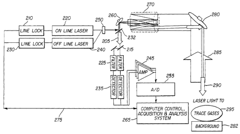
Fig 2 is a block diagram of a prior art DIAL- gas detection system.
Fig 3 is a block diagram of a 3-line tunable DIAL laser fluid pipeline leak
detection system according to the present invention.
Fig. 4 is an exemplary high-level block diagram of the 3-line tunable DIAL
laser fluid pipeline leak detection system according to the present invention.
Fig. 5 is a mid-level block diagram of the 3-line tunable DIAL laser fluid
pipeline leak detection system according to the present invention.
Fig. 6 is a mid-level block diagram of the 3-line tunable DIAL laser fluid
pipeline leak detection system, according to the present invention, with the
list of
components for each primary subsystem.
CA 02550156 2006-06-09
WO 2005/064316 PCT/US2004/042485
-6-
Fig. 7 is a block diagram of a 1-micrometer optical parametric oscillator
and amplifier for generating a selected wavelength.
Fig. 8 is a block diagram of a 1-micrometer optical parametric oscillator
and amplifier for generating one of the selected 3-line wavelength.
Fig. 9 is a block diagram of the flight path-finding system according to the
present invention.
Fig. 10 is a block diagram of the laser pointing system according to the
present invention.
Fig 11 is a block diagram of the 3-line tunable DIAL laser fluid pipeline
leak detection system.
To facilitate understanding, identical reference numerals have been used,
where possible, to designate identical elements that are common to the
figures.
DETAILED DESCRIPTION OF THE INVENTION
The present invention described herein addresses the measurement of
gases associated with oil and gas leakages from pipelines. This invention
relates to an
oil and gas pipeline leak detection system and method of detecting gases in
the
atmosphere and more particularly, but not by way of limitation, to detecting
pipeline
leaks based upon differential absorption lidar (DIAL) sensing techniques
operating in a
mid-infrared 2 to 5 micrometers, spectral range. In general, the following
fluids may be
detected or explored: gas, volatile oil, light crude oil, heavy crude oil, and
hazardous.
The gas concentrations are mapped over an area and the maps are analyzed for
concentration anomalies. The gas anomalies are interpreted to evaluate the
underground pipeline leak.
In the discussion of the present invention, the term "target fluids" is used
to indicate fluids that are associated either directly or indirectly with
pipeline leaks.
Target fluids can mean either liquids or gases. The measured atmospheric
concentrations of target fluids form the basis of the new infrastructure
assessment tool
as described herein. Target fluids must have some unique characteristics to
their
association with the pipeline leak. For example, methane is produced in a
number of
ways. It may occur in the atmosphere as a result of emission from a
hydrocarbon
deposit, emission from a coal deposit, emission from wetlands with active
populations of
methane producing bacteria, emission from a leaking natural gas pipeline, etc.
Sources
of methane other than a pipeline leak are said to be environmental
interferences.
Environmental interferences complicate the association between a target fluid
and the
pipeline leak; and will vary in magnitude and type with standard geological
factors such
as soil type, hydrology, subsurface structure and composition, as well as
atmospheric
CA 02550156 2006-06-09
WO 2005/064316 PCT/US2004/042485
conditions, weather and land use. A unique gas mixture such a methane/ethane
is a
useful target fluid for natural gas pipelines. Individual gases or gas
combinations that
have very unique associations with the pipeline leak provide the most valuable
signals
indicating the presence of a leak.
The present invention teaches the use of a differential absorption lidar
(DIAL) that samples along a path through the atmosphere. A wide range of
instruments
have been developed which detect most trace gases in the atmosphere. These
instruments can be loosely categorized as techniques that sample air at a
specific point
in space and remote sensing systems such as the numerous satellite- or aerial-
based
systems which provide large-scale measurements of gas concentrations. There
are
numerous types of gas sources that, because of their unique spatial and
temporal
properties, cannot be accurately characterized by these techniques. Monitoring
emissions from such sources requires a system that can measure minute
concentrations
quickly and over long paths, remotely. Long path differential absorption
lidars (DIALS)
typically meet these requirements.
One aspect of the present invention is to utilize an airborne platform-based
3-line tunable differential absorption lidar (DIAL) laser optical sensor for
remote
quantitative detection of leaks from a natural gas or oil pipeline. Another
aspect of the
present invention is to select the trace gases that optimally characterize
fluid pipeline
leaks. For the present invention, the gases released into the atmosphere from
both gas
and oil pipeline leaks are evaluated and methane and ethane are selected for
robust
detection of both types of leaks. Another aspect of the present invention
optimally
selects the molecular transition of the optical absorption characteristics of
methane and
ethane within the mid-infrared region of the electromagnetic spectrum. Methane
and
ethane absorption characteristics are analyzed and two on-wavelengths (also
referred to
as on-line) and one off-wavelength (also referred to as off-line) for the
methane, ethane
and the earth-surface type (background) respectively, are selected for the
leak detection.
The on-line wavelengths are selected close to the peak of the target gas
optical
absorption with minimum interference from other gases. The off-line wavelength
is
selected near the wing of the target gas optical absorption, with minimum
interference
from other gases and high ground surface reflectivity. In the present
invention, the on
line and off-line wavelengths are selected to be 3369.8, 3389 and 3429
nanometers for
ethane, methane and the background, respectively. Note that these specific
wavelengths
have not been used in the prior art and as it was mentioned earlier, the
criteria for the
on-line wavelength-selection is that the absorption is expected to be only
dominated by
methane and ethane, and for the off-line wavelength, the absorption is
expected not to
be dominated by methane, ethane or by atmospheric particles.
CA 02550156 2006-06-09
WO 2005/064316 PCT/US2004/042485
_g_
Another aspect of the present invention uses stable continuously tunable
lasers. Therefore, three ND:YLF continuously tunable lasers were designed and
implemented for methane and ethane trace gases and background, respectively.
The
present invention also measures the target gases' concentration path-lengths.
Therefore, the 3-line tunable DIAL laser system, according to the present
invention,
measures the concentration path-lengths for the two selected target gases for
each
scanned spot. The present invention employs a statistical analysis of the
multiple
concentration path-length measurements for the two target gases along the
flight path.
Finally, the present invention displays, stores and communicates the position,
size, and
shape of the gas plumes associated with pipeline leaks.
The present invention, as schematically shown in Fig.l, comprises an
aircraft 110, an on board 3-line tunable differential absorption lidar (DIAL)
laser Fluid
Pipeline Leaks Detection System 120, a transmitted laser beam 130, trace gases
150, a
buried pipeline 160, a leak area 170, a ground surface type 180, a 3-
dimensional section
of the ground with the pipeline, a leak area and the trace gases 190, an
aircraft flight
altitude 140 (N 500 m), and a cleared pipeline access area 105. Based on an
optimally
previously determined flight path, the aircraft 110 flies toward buried
pipeline 160, in
order to detect leak area 170, comprising natural gas or oil pipeline leaks.
During the
flight an on board GPS and Inertial Measurement Unit (IMU) positional system
(not
shown herein) guide the pilot toward a target location that emanates trace
gases 150.
When the aircraft reaches the target location, the laser beams 130 are
automatically
pointed to the target as the scanner system scans the surrounding central
target
regions. Then a returned light is analyzed to develop two-dimensional gas-maps
or
images of both methane and ethane plumes in units of concentration path-
length.
Tn a DIAL measurement system two, essentially single-wavelength, laser
pulses are transmitted. One laser pulse of a specific wavelength is chosen
which is
absorbed by the gas of interest, the other laser pulse at a different
wavelength is not
absorbed. The energy reflected back to the sensor for both wavelengths is
measured
and combined to generate an estimate of the target gas' concentration length.
This
section describes this process in more detail.
The energy which is reflected back to the sensor is described by the
following relationship,
E ~c ETP~ eXPL-2(CLp +CbgR)6(7~)~ 1
z '
R
where ET is the transmitted energy, p~ is the surface reflectance, CLP is the
concentration-length product of the plume, Cb9 is the background concentration
of the
CA 02550156 2006-06-09
WO 2005/064316 PCT/US2004/042485
_g_
gas, R is the range to the surface, and 6(7~) is the absorption cross-section
of the gas as
a function of wavelength. In this work, it will be assumed that ET is constant
from pulse-
to-pulse (since any changes can be measured and accounted for), that p~ is
0.005 and
does not depend upon wavelength for the small range of wavelengths considered,
that R
is nominally 500 m, and that the cross-section 6(~,) does not change
significantly due to
pressure and temperature changes along the path. This last assumption would
not be
true for paths which change by many kilometers in altitude, but is reasonable
for a 500
meter aircraft altitude. Also, we note that it might be necessary to re-
measure ~(7~)
when the system operates in regions where ground level is much higher than sea
level.
The term which is wavelength dependent in Equation (1) is the cross-
section, a(~,) . Many of the terms which do not change can be canceled by
measuring at
two wavelengths and dividing the results. Let E1 denote the energy measurement
at one
wavelength, and EZ denote the measurement at a second wavelength. Then
El - exp[-2(CLp +CbgR)a(y)]
E2 exp[-2(CLp +CbgR)a(~,2)]
Taking the natural logarithm of the above,
log LE-,1 =(CLp+CbgR)(~(~2)-a(~i))~
2
The cross-section can be measured offline or in real time (using a gas cell
onboard the
aircraft). In either case, the cross-section at each wavelength is a known
value,
therefore
1 log EI = (CLp +CbgR) . (4)
2W~2 ) - ~(~1 )) E2
Equation 4 is the measurement process modeled in this work. However,
there are additional processing possibilities, since R can also be measured by
the system
and Cb9 can be estimated or measured. It would then be possible to produce an
estimate
of CLP. In the final system, it is likely that an estimate of CLp alone will
be an important
part of the product, but analysis of Equation 4 is sufficient to characterize
plume
detection performance.
In equation (4) the effect of differences in atmospheric concentration
length (Ck) has not been considered. But equation (5) includes the effect of
differences in
atmospheric concentration length, where Ck can be estimated or measured.
CA 02550156 2006-06-09
WO 2005/064316 PCT/US2004/042485
-10-
2~~~~ )~- ~~~ )) log El 2Ck = (CLn + CbgR) (S)
2 1 2
In order to appreciate the present invention, a system block diagram of a
prior art DIAL system is shown in Fig. 2. Single on-line laser 220 and one off-
line laser
240 are locked by electronic control signals 275 onto two different
wavelengths by line
lock amplifiers 210 and 230, the on-line wavelength is selected close to the
peak of a
target gas' optical absorption and the off-line wavelength is selected near
the wing of the
target gas' optical absorption wavelength. The on-line and off-line laser
beams 220 and
240, respectively, are combined by Holographic Grating 250 and transmitted by
a fast
scan mirror 260 trough a telescope 270 and directed and guided by the slow
scan mirror
280. Finally, for the region of interest, trace gases in the atmosphere near
the ground
are sequentially scanned by laser beams 290. Then, the laser beam 290 is
scattered and
transmitted by a trace gas 295, reflected by the background 282 scattered and
transmitted again by to trace gas 295. Next, the returned light 285 is
reflected by the
slow scan mirror 280 into a Telescope 270 and is separated by beam splitter
232 from
the transmitted laser beam 205 to another set of beam splitters 215, then
passes
through a set of filters 225 to only pass the on-line and off-line
wavelengths, then onto a
set of detectors 235 to optimally convert the returned light to an electronic
signal. Then
the signal is electrically amplified by an amplifier 245 and converted to a
digital signal by
a set of A/D converters 255. The digitized signal is processed and analyzed by
the
computer 265 to compute the ratio between the on-line and off-line returned
signals,
which is directly proportional to the target gas concentration path-length.
In the prior art, only one trace target gas' signature characteristic is
selected and measured. In contrast, in the present invention more than one
trace target
gas' signature characteristic is used to improve the robustness, sensitivity
and
performance capability of the gas and oil pipeline leak detection system. A
simplified
system block diagram of the present invention, the 3-line tunable DIAL laser
optical
sensor system, is shown in Fig. 3. One on-line laser for methane 320, one on-
line laser
for ethane 395 and one off-line laser 385 are locked by electronic control
signals 355
onto three different wavelengths by line lock amplifiers 310, 36S and 375,
respectively;
the on-line wavelengths are selected close to the peak of a target gas'
optical absorption
characteristics and the off-line wavelength is selected near the wing of the
target gas'
optical absorption wavelength. The two on-line and one off-line laser beams
320, 395,
and 385, respectively, are combined by holographic grating 340 to form
combined laser
beam 330. The combined laser beam 330 is transmitted by a fast scan mirror 350
trough a telescope 302 and directed and guided by a slow scan mirror 304 to
form laser
beam 360. For the region of interest, trace gases in the atmosphere near the
ground are
CA 02550156 2006-06-09
WO 2005/064316 PCT/US2004/042485
-11-
sequentially scanned by laser beam 360. Laser beam 360 is scattered and
transmitted
by trace gas 308, reflected by background 309, scattered and transmitted again
by trace
gas 308, becoming returned light 306. The returned light 306, from the
transmitted
laser beam 360, is reflected by the slow scan mirror 304 into the telescope
302, and
separated by a beam splitter 331 to form a return light 370. Returned light
370 passes
through a set of beam splitters 380 before encountering a set of filters 390.
Filters 390
only pass the two on-line and one off-line wavelengths, before a set of
detectors 305
optimally converts the returned light to an electronic signal. The electronic
signal is
electrically amplified by an amplifier 315, converted to a digital signal by a
set of A/D
converters 325. The digitized signal is processed and analyzed by a computer
335 to
compute the ratio between the two on-line and off-line returned signals, which
are
directly proportional to the target gases concentration path-lengths.
Multiple sources of a selected target gas, for example methane, and
variability of the ground surface's reflectivity type increase the probability
of a false
alarm. Hence, the 3-line tunable laser DIAL system implemented by the present
invention minimizes false alarms from detecting multiple sources of target gas
and
variable ground surface reflectivity.
An exemplary block diagram of the system is shown in Fig. 4. Consumer-
acquired pipeline positional data is first processed, filtered, normalized,
and stored in
pipeline positional database 410. Normalizing the consumer-acquired pipeline
positional
data entails applying one standard file format to the consumer-acquired
pipeline
positional data. The normalized positional data for a region of interest is
downloaded
into a computer control, acquisition and analysis system 450. A flight path-
finding and
laser pointing system 430, in communication with the computer control,
acquisition and
analysis system 450 guides an aircraft along a predetermined flight path and
points the
laser beams at a predetermined point. As part of the flight path-finding and
laser
pointing system 430, on-board aircraft positional and motion measurement
instruments
take corrective action to guide the aircraft and the laser to other points
along the flight
path. A sensor system 440, also in communication with the computer control,
acquisition and analysis system 450, transmits laser beams to leaking trace
fluids 420
and also receives returned light from the leaking trace fluids 420. The
computer control,
acquisition and analysis system 450 sends control signals to the sensor system
440 and
receives signals from the sensor system 440 to monitor, store and analyze leak
concentrations.
A more detailed block diagram of the present invention and its primary
sub-system 500 is shown in Fig. 5. The primary subsystem 500 includes an
Interface
System 510 with Graphical User Interface (GUI) software for starting,
stopping, setting-
CA 02550156 2006-06-09
WO 2005/064316 PCT/US2004/042485
-12-
up, monitoring and controlling of the operations of the primary subsystem 500.
A
Computer System 520 has a high end powerful processor (e.g. an Intel
PentiumT"' chip or
an AMD AthIonT"', or an IBM PowerPC 750CX), and various hardware components,
such
as a signal processor and analog to digital (A/D) converters, along with one
or more
interfaces for communicating with other components of the primary subsystem
500. For
example, there are links to a scanner 550, a control system 530, a signal
acquisition and
analysis system 505, and a flight path-finding and laser pointing system 525
with a
Global Positioning System (GPS). The entire primary subsystem has removable
hardware drives and various monitors to display process conditions.
The Signal Acquisition and Analysis System 505 has a signal process board
for signal processing and acquisition and analysis software to measure, record
and
display measured concentration levels of ethane and methane.
The primary subsystem 500 includes an aircraft system 535. The aircraft
system 535 may be a CessnaT"' 402B aircraft or other aircraft capable of
flying at N 500
meter altitude with speed of N 67 meter per second, carrying a 3-line tunable
DIAL laser
fluid pipeline leaks detection system and the on board flight path-finding and
laser
pointing system 525.
Specifically, the flight path-finding and laser Pointing System 525 includes
a portable global positioning system (GPS) and an Inertial Measurement Unit
(IMU) and
links to the computer system 520 to continuously update the position of the
aircraft and
direct the laser beams, utilizing laser system 540 via the control system 530,
in
accordance with the current position of the aircraft.
A Pipeline Positional Database 515 includes software algorithms to
process, filter and normalize a consumer acquired pipeline positional data set
and an on
board GPS and IMU real-time positional data to predict an optimal flight path
and update
the pipeline positional data base with the predicted optimal path map.
Control System 530 includes all electronic and temperature control circuits
for operating the 3-line tunable laser system 540. For example, precise
control feedback
loops for the current requirement for each laser diode, temperature sensors,
laser cavity
tuners that lock each the Nd:YLF; laser outputs to its respective seed laser
source,
timing circuits that generate timing pulses for timing of each laser
activation, along with
timing of the Q-switching in the laser system 540 and timing for the signal
acquisition
and analysis system 505. Accordingly, the laser system 540 includes im
plementation of
a 3-line, direct detection, DIAL laser transmitter system.
A Laser system 540 operates in the mid-wave infrared spectral region and
employs three all solid-state Nd:YLF laser transmitters. These lasers will
output single
CA 02550156 2006-06-09
WO 2005/064316 PCT/US2004/042485
-13-
frequency light and operate at pulse repetition rates of 3050 Hz. Each laser
will produce
about 0.68 W of output power. The lasers are tunable and locked to the desired
wavelengths. The laser system 540 also provides IO nanoseconds of short single
frequency pulses at three different wavelengths.
A Scanner System 550 includes fast scan rotating wedges and slow scan
pitch & roll compensator wedges subsystems. The fast scan rotating wedges are
responsible for directing the transmitted laser light coming from the transm
fitter laser
system 540 to the target area. The backscattered light from the target area is
also
directed into the detection (receiver) system 590 by the scanner system 550.
Scanner
system 550 also generates a circular rotating illumination pattern around the
optical
centerline of the transmitter/receiver subsystems. The slow scanning subsystem
pitch &
roll compensator of the scanner system 550 directs the center of the circular
illumination
path to the target area.
Telescope System 560 is an optical system that is also called the receiver
telescope. The primary function of telescope system 560 is to collect the
backscatter
light from the target and focus it to the detection system 590. Telescope
system 560 is
focused at the target area and the portion of the backscatter light that falls
on the
receiver telescope primary mirror is focused into a collimated beam by the
telescope
secondary mirror and the collimating fens. A high optical transmission
interface filter,
with an optical bandwidth that encompasses the three wavelengths, serves to
reject wide
band background light from the reflected solar radiation, and hot-surfaces
thermal
emissions.
A Detection System 590 comprises the components and subsystems
needed to detect and electronically condition the returned signal at three mid-
IR
wavelengths. The detection system 590 may also be termed the receiver system.
The
detection system 590 employs direct detection of signal power and uses three
separate
detectors, where each detector, views different percentages of the returned
beam, to
achieve a large dynamic range due to both ground (background) reflectivity
variations
and the attenuation from the absorbing trace gases. Subsequently, the detected
electronic signals are amplified and digitized,
The primary subsystem 500 is designed to detect trace fluids 570. For gas
and pipeline leaks, trace fluids 570 are methane and ethane. One objective is
selection
of characteristics associated with trace fluids 570, as fluid pipeline leaks,
that will enable
one to reliably and robustly detect possible pipeline leaks.
Detection of trace fluids 570 may be affected by background 580.
CA 02550156 2006-06-09
WO 2005/064316 PCT/US2004/042485
-14-
Background 580 is defined as reflection from the ground surface.
Background 580 may be bushes, soil, water, trees, sand and so on. The
background 580
reflects the backscattered light to telescope system 560.
A monitor 545 is included in primary subsystem 500 to display various
S Graphical User Interfaces (GUIs) that enable monitoring and analysis of
relevant process
conditions for the 3-line DIAL laser fluid pipeline detection system. The
computer
system 520 sends the control signals to the control system 530 and receives
information
monitoring signal information from the control system 530. The computer system
520
also accesses the prior optimally determined flight path data base interface
510 and the
on board GPS and IMU positional path-finding and laser pointing subsystem 525
to point
the laser beams, while controlled by the control system 530 and determines the
next
target location which is in turn passed to the aircraft system 535. The
control system
530 sends an electronic locking signal to the laser system 540 and also
controls the
temperature of the all the diode lasers in laser system 540. The laser system
540
generates three nearly simultaneous at pulse laser beams (no more than 10
nanoseconds a part) at the specified wavelength for transmission to the target
location.
The transmitted laser beams pass through the scanner system 530, the
atmosphere, the
trace fluids 570; and finally strike the background 580. The returned signal
from the
background 580 passes again through the trace fluids 570 and the atmosphere,
back to
the telescope system 560. The returned light enters the aperture of telescope
system
560 and is focused on the detectors in detection system 590. The detected
analog signal
is optimally digitized for the optimal dynamic range by the detection system
S90 and the
digitized signal will be analyzed by the signal acquisition and analysis
system 505 to
estimate the trace fluid's target concentration path length. The software
algorithm in
computer system 520 statistically analyzes the estimated concentration path
length.
Finally the analyzed signals are stored in the computer system hard disk and
the monitor
540 displays two-dimensional or three-dimensional gas-maps.
The components of each primary subsystem, as shown in Fig. 5, for
generating source #1 laser of the present invention are described further in
Fig. 6. The
components described herein whether individually and/or grouped are not solely
exclusive. Equivalent components may be substituted and are anticipated.
Referring to Fig. 6, a laser system 640 may include a transmitter, pump
lasers, Optical Parametric Oscillator (0P0), Optical parametric Amplifier
(OPA), injection
seeding, a computerized laser source controller and a line locking mechanism.
The
components of the scanner system 650 may include a mirror, fast scan wedges,
slow
scan pitch/roll compensation wedges, and a window support/enclosure.
CA 02550156 2006-06-09
WO 2005/064316 PCT/US2004/042485
-15-
Detection system 640 may include an optical filter, optical matching,
detectors, amplifiers and analog to digital convectors. Whereas, the flight
path-finding
and laser pointing system 630 may include navigational components such as a
global
positioning system (GPS), an Inertial Measurement System (IMU) and high
bandwidth
aircraft position and altitude updating equipment.
The signal control, acquisition and analysis system 620 may include
components that enable signal control, signal acquisition, signal analysis,
ancillary data
acquisition, command of the scanner, acquisition of navigational data and data
recording. User interface system 610 may have components for user interfacing,
pilot
interfacing, and a flight plan that incorporates a target pipeline map. A
monitor 670
displays a GUI, process conditions and concentration leak rates. Power
controller 680
provides electric power to all the sub-systems.
The signal control, acquisition and analysis system 620 (comprising 520,
530 and 505 as shown in Fig 5.) sends the control electronic locking signals
to the laser
system 640 and receives monitoring signal information from the laser system
640. The
signal control, acquisition and analysis system 620 also accesses the
previously
determined optimal flight path data from flight path database interface 610;
and controls
the on board GPS and IMU positional path-finding and laser pointing subsystem
630 to
point the laser beams through the scanner system 650. Additionally, the signal
control,
acquisition and analysis system 620 determines the next target location and
passes the
target information to the aircraft system 535 (shown in Fig. 5). The signal
control,
acquisition and analysis system 620 also controls the temperature of the all
the diode
lasers in the laser system. The laser system 640 generates three nearly
simultaneous
pulse laser beams (e.g., within 10 nanoseconds a part) at a specific
wavelength and
transmits the pulse laser beams to the target location through the scanner
system 650.
The transmitted laser beams pass through the atmosphere, through the trace
fluids, and
finally strike the background. The returned signal from the background passes
once
again through the trace fluids and the atmosphere as it returns to the
telescope 690.
The returned light enters the aperture of telescope 690 and is focused on the
detectors in
the detection system 660. The detected analog signal is digitized for the
optimal
dynamic range used by the detection system 660 and the resulting digitized
signal is
analyzed by the signal control, acquisition and analysis system 620 to
estimate the trace
fluid's target concentration path length. The software algorithm statistically
analyzes the
estimated concentration path length in the signal control, acquisition a nd
analysis
system 620, Finally the analyzed signals are stored in a hard disk of the
signal control,
acquisition and analysis system 620 and the monitor 670 displays two-
dimensional or
three-dimensional gas maps.
CA 02550156 2006-06-09
WO 2005/064316 PCT/US2004/042485
-16-
Fig. 7 shows the simplified block diagram of the laser source's transmitter,
which employs a 1 pm Nd:YLF laser that pumps an optical parametric oscillator
(OPO)-
optical parametric amplifier (OPA) frequency converter. The OPO is seeded to
ensure
single-frequency operation. As shown in Fig. 7, # 2 laser source (70S) and # 3
laser
source (715) are generated and combined by the spatial filter 790 infio a
single
transmitted beam.
Different laser source selection approaches were considered based on the
source efficiency, n, is the electrical-to-optical efficiency of the approach
not including
seed laser power and cooling power.
The short pulse width and precise timing of the pulses dictates the use of
actively Q-switched lasers. Q-switching is advantageous for short pulses and
active
control is advantageous for precise timing. The laser source must be compact
and
efficient to be compatible with what is likely limited aircraft space and
power. There are
no commercially available sources that meet these requirements. Conventional
laser
technology generally uses nonlinear optical techniques For shifting the
wavelength of
well-developed lasers in the short-wave-infrared (SWIR) or long-wave infrared
(LWIR) to
access mid-wave infrared (MWIR) wavelengths, such as the wavelengths employed
in the
present invention. Examples of SWIR and LWIR lasers that can be frequency-
shifted to
the MWIR are neodymium (Nd) solid-state lasers and carbon dioxide (C02) gas
lasers,
respectively.
Referring to Fig. 7, a 1 pm DPSSL/OPO-OPA laser source single tunable
frequency technique is used to generate the selected wavelengths. OPO-OPA 750
is
pumped by a Q-switched Nd:YLF laser 720 operating at 1047 nm. The Nd:YLF laser
is
pumped by a fiber-coupled diode laser 710 operating at 805 nm and that is also
injection
seeded by CW (continuous wave), single frequency 1047 nm light from a common
seed
source. The OPO-OPA 750 is injection seeded by external-cavity diode laser
operating at
N 1510 to assure single frequency output at 3400nm. The combination of Nd: YLF
seed
laser 730, ECDL seed laser 740, 1 pm DPSSL 710, OPO - optical parametric
amplifier
(OPA) 750 subsystems, shown in Fig. 7, increases the wavelength conversion
efficiency
by using two nonlinear processes in the OPO cavity. An OPA is used to convert
some of
the unneeded power produced by the OPO crystal into 3400 nm output. As shown
in Fig.
7, the OPO process converts the Nd:YLF pump wavelength (1047 nm > 3400 nm +
1510
nm) and the OPA process then produces more 3400 nm output (1510 nm > 3400 nm +
2720 nm). This means that a single pump photon can produce two 3400 nm
photons.
More MWIR photons are produced than incident pump photons as a result of
greater than
100% photon conversion efficiency. Therefore, the two-step conversion leads to
a higher
CA 02550156 2006-06-09
WO 2005/064316 PCT/US2004/042485
-17-
overall optical-to-optical conversion efficiency, N25% or greater. Thus, the
overall
system efficiency with this particular approach is N2.
A block diagram of a single laser source, in greater detail, is shown in Fig.
8. The output of an 805 nm pump diode laser 850 passes through an optical
fiber is
collimated and focused into a Nd:YLF rod 860 to provide gain for the laser.
Also the
Nd:YLF laser 860 is Q-switched and seeded by the 1047 nm meteor seed laser
805. The
1047 nm output of 860 is injected into the OPO-OPA laser cavity 870 through a
thin-film
polarizer. Also the OPO-OPA laser cavity 870 is seeded by the 1510 nm ECDL
seed laser
815. The OPO-OPA is a 4-mirror ring cavity containing 2 PPLN (periodically-
poled lithium
niobate crystals). The first crystal is chosen to produce 3400 nm and 1510 nm
light with
1047 nm pump, while the second crystal (should be a different #) is chosen to
produce
3400 nm and 2700 nm light with 1510 nm pump. A cavity 870 resonates at 1510 nm
and is injection seeded at this wavelength through the output coupler. The
cavity length
is locked to the seed frequency by 840 by using the Pound-Drever-Hall (PDH)
technique
with Radio frequency modulation applied to the diode laser seed 1510 nm. Diode
subsystems 810 and 890 controls temperature and current of the pump diode
laser 850,
respectively. Subsystem 820 controls the Q-switching and seeding of the cavity
via
operation 860. Meteor controller 845 controls the 1047 nm wavelength of seed
laser
805. The 855 subsystem locks the cavity length of seed laser 860. A seed laser
controller 865 controls the 1510 nm seed laser wavelength; and seed laser
wavelength
electronics 875 locks the seed laser at a desired wavelength.
A block diagram of a flight path-finding and laser pointing subsystem is
shown in Fig 9. As mentioned earlier, the present invention measures the trace
signature gases of the fluid pipeline leaks concentration level within a
predefined
corridor, along a pipeline path. To perform this task, the laser pointing
subsystem
actively and continuously directs the three combined beams according to the
current
position of the aircraft and the desired measurement position on the ground. A
fast
rotating circular scanner 905 and a slow rotating pointing scanner 915 directs
the three
beams in a constant and circular pattern according to the current aircraft
position and
desired corridor coverage. An ideal flight plan path will be generated for
optimal ground
coverage along the flight plan. A GPS and/or IMU system 920 is queried at 100
HZ via
an update position and altitude module 930 to determine the current aircraft
position
and altitude. Based on the current position, the nearest point on the ideal
flight plan will
be determined along with its associated ground position. The circular pattern
is pointed
at this ground position with reference to the current altitude. The current
positional
information is used by a computer acquisition and control system 940 to
communicate
with a scanner controller/driver 990 for controlling the slow rotating
pointing scanner
915 to the target area and display the information to a pilot data display
950. Either or
CA 02550156 2006-06-09
WO 2005/064316 PCT/US2004/042485
-18-
both of the scanner controller/driver 980 and scanner controller/driver 990
control
drivers that direct the three-laser beams to the target position on the
ground. Scanner
controller/driver 980 provides a scan instruction 960 for every 1 tick/scan @
20-40 Hz to
the computer acquisition and control system 940.
The pipeline positional database subsystem software algorithm is shown in
Fig. 10. For stable pointing control, a unique pointing position is needed at
every
moment during the flight. Because the pipeline may travel an irreg ular path
that cannot
be closely followed by the aircraft, ambiguities associated with the pointing
target are
expected. Therefore, initially, a preflight pipeline positional information
operation 1010
and an ideal flight path operation 1030 are used to calculate a 1-to-1 look up
table in
operation 1020. Subsequently, start operation 1040 begins flying the aircraft,
at the
predetermined altitude, to the target position. The aircraft's current
positional data is
measured by an on board GPS and IMU in operation 1050, based on the target
position.
Finding the nearest latitude, longitude, altitude along the ideal flight path
occurs in
operation 1070. Finding a unique corresponding point on the ground happens
subsequently in operation 1090. Whereupon operation 1005, the required wedge
angle
to point at the ground point is calculated and provided to a pilot course
correction
information operation 1080, which points a scanner to direct the three beams
to the
nearest target ground point in operation 1060.
A schematic of the developed 3-line DIAL laser gas pipeline leaks detection
system, with a more detail information of the transmitter and receiver
(transceiver)
subsystem, is shown in Fig. 11. The three laser sources for the off-line and
two on-line
wavelengths (1110, 1120, 1130, respectively) are first split by the three beam
splitters
1140 to monitor their power by a set of power meters 1170, second, the three
laser
sources are combined by a holographic grating 1155 so that they are collinear.
Collinear
beams 1112 enter into a beam-combining grating 1114 to provide a fixed finite
source
aperture. In this way, any drifts that might occur in laser alignment will
show up as
easily recognized transmitted pulse energy discrepancies, but will not affect
gas
concentration length measurement calibrations. The multi-wavelength source
beam is
then introduced into a set of directing optical path mirrors 1116. A reflected
custom
optic beam enters onto a galvanometer-driven scanning fast mirror 1118 and is
transmitted to illuminate the ground via a large aperture slow scanning mirror
1122 that
is also used to compensate the scan swath for aircraft roll and off-track
flight errors. As
the galvanometer-driven scanning fast mirror 1118 swings through a full angle
of 25
degrees, the source beam swings through a 50 degree arc on entering a
telescope 1108.
Telescope 1108 produces a 5 degree full angle scan of the transmitted beam and
traces a
35 m wide ground swath scan 1126 of the laser footprint 1132 on the ground
(the
additional angle width is included to compensate for aircraft crab angle).
Light scattered
CA 02550156 2006-06-09
WO 2005/064316 PCT/US2004/042485
-19-
from the receiver footprint 1128, enters the full telescope aperture via a
slow track
correction mirror. The fast scanning galvanometer-driven mirror 1118 also
reflects the
received light in the exit pupil. Thus, the galvanometer-driven scanning fast
mirror 1118
shifts the central angle field of view (FOV) of the receiver (in other words,
equivalent to
shifting the receiver footprint 1128 on the ground) synchronously with the
optical
centerline of the transmitted beam. The received light then passes through the
custom
beam-splitter 1111, through a narrow band interference filter 1106, and the
filtered light
1104 onto the signal detector 1102, onto the amplifier 1190; and the amplified
light
1180 is digitized by 1146. In order to monitor the stability of the locked
three
wavelengths, a percentage laser beam 1150 from the on-line methane laser
source 1130
is passed to subsystems 1160. The gas-cell spectral line pass filters 1165
only pass the
selected laser lines, then a set of detectors 1185 convert the laser light to
analog
electronic signals before passing these signals through a set of power meters
(energy
meters) 1175 to monitor the laser's power. Then the measured laser power
passes
through a set of low rate A/D coveters 1195 and finally the output of these
A/D
converters 1195 is read by computer control acquisition & analysis system
1148. A
scanner electronic controller subsystem 1144 controls a fast scan mirror 1122
and a slow
san mirror1124. A pipeline positional database 1142, the computer control,
acquisition
and analysis 1148 and the flight path-finding and laser pointing 1152
subsystems shown
in Fig. 11 were described earlier.
The present invention can be tuned to detect a multiple components of
hydrocarbon gases by changing the wavelengths of the 3-line DIAL laser sensor
incorporated herein.
The invention has been described with reference to one or more
embodiments. However, it will be appreciated that a person of ordinary skill
in the art
can effect variations and modifications without departing from the scope of
the invention.
The present invention is tuned to detect gas/oil pipeline leaks, however, it
will be
understood by anyone skilled in the art that the present invention may be
tuned for the
detection of hazardous or other materials of interest. It will be further
understood that
the method can be advantageously used for the exploration of oil/gas or other
natural
resources of interest.
CA 02550156 2006-06-09
WO 2005/064316 PCT/US2004/042485
-zo-
PARTS LIST
105 Cleared Pipe access
110 Aircraft
120 Airborne 3-line tunable DIAL laser fluid pipeline detection system
130 Transmitted laser beam
140 Flight altitude
150 Trace gases
160 Buried pipeline
170 Leak area
180 Ground surface type: background
190 A 3D section of the ground
205 A percent of combined laser beam
210 Line lock amplifier
215 Beam splitter
220 On-line laser
225 Filter
230 Line lock amplifier
232 Beam splitter
235 Detector
240 Off-line laser
245 Amplifier
255 Analog to Digital converter A/D
250 Holographic grating
260 Fast scan mirror
265 Computer control, acquisition and analysis system
270 Telescope
275 Electronic control signals
280 Slow scan mirror
282 Ground surface type: Background
285 Returned light
290 Transmitted laser light
295 Trace Gases
370 A percent of combined laser beam
310 Line lock amplifier
331 Beam splitter
390 Filter
320 Methane on-line laser
365 Line lock amplifier
CA 02550156 2006-06-09
WO 2005/064316 PCT/US2004/042485
-21-
395 Ethane on-line laser
380 Beam splitter
305 Detector
375 Line lock amplifier
385 Off-line laser
315 Amplifier
325 Analog to Digital converter A/D
340 Holographic grating
350 Fast scan mirror
335 Computer control, acquisition and analysis system
302 Telescope
355 Electronic control signals (Laser line lock communications)
304 Slow scan mirror
309 Ground surface type: Background
306 Returned light
360 Transmitted laser light
308 Trace Gases
410 Pipeline positional data base
420 Leaks trace fluids
430 Flight pathfinding & laser pointing system
440 Sensor system
450 Computer control, acquisition and analysis system
460 Monitor
510 Interface system
520 Computer system
530 Control system
540 Laser system
550 Scanner system
560 Telescope system
570 Trace fluids
580 Background
590 Detection system
505 Signal acquisition and analysis system
515 Pipeline positional database
525 Flight pathfinding and laser pointing system
535 Aircraft system
610 Interface system
620 Signal control, acquisition and analysis system
CA 02550156 2006-06-09
WO 2005/064316 PCT/US2004/042485
-22-
630 Flight pathfinding and laser pointing system
640 Laser system
650 Scanner system
660 Detection system
670 Monitor
680 Power control converters
690 Telescope system
705 Single laser source # 2
715 Single laser source # 3
710 Fiber-coupled diode laser
720 The diode-pumped Q-switched, Nd:YLF laser
730 The Nd:YLF seed laser
740 External cavity diode laser (ECDL) seed laser
750 The Optical Parametric Oscillator (OPO)-Optical Parametric Amplifier(OPA)
760 Beam splitter
770 Reference gas cell
780 Telescope
790 Holographic grating/spatial filer
810 Diode temperature controller
820 Electro-optic Q-switch controller
830 Temperature stabilization
840 OPO cavity length locking to seed laser
850 Diode laser 805 nm
860 Q-switched Seeded Nd:YLF laser
870 OPO-OPA injection seeded
880 Spatial filter/beam combiner to combine the 3 produced lasers into a
single
transmit beam
890 Diode current controller 805 Meteor Nd:YLF seed laser
815 OPO seed laser external cavity diode laser
835 Reference gas cell
845 Meteor controller
855 Nd:YLF cavity length locking seed laser
865 Seed laser controller
920 GPD/IMU system
930 Position and altitude update
940 Computer acquisition and control system
950 Pilot display data
960 Fast scanner update signal
CA 02550156 2006-06-09
WO 2005/064316 PCT/US2004/042485
-23-
970 Slow scanner update signal
905 Fast scanner controller drive
915 Slow scanner controller drive
980 Fast rotating scanner
990 Slow rotating scanner
1010 Pipeline coordinate map from survey
1020 Look up table (LUT)
1030 Idea flight path data
1040 Start the target location and path calculation
1050 Read current data (latitude, longitude, roll, pitch and altitude)
1060 Point scanner (pointing laser)
1070 Nearest point LUT
1080 Pilot path correction information
1090 Corresponding ground point coordinate in LUT
1005 Pointing angle calculation
1150 A percent of combined laser beam
1110 3389 nm off-line laser light source
1120 3336.8 nm ethane on-line laser light source
1130 3429 nm methane off-line laser light source
1140 Beam splitter
1155 Holographic grating
1170 Power meter
1112 Single combined laser beams
1114 Beam expander
1116 Directing mirror
1118 Dual-wedge fast conical scanner
1122 Dual wedge conical pointing scanner
1124 Reflected light from ground surface (returned light)
1126 Ground Swath
1128 Receiver footprint
1132 Laser footprint
1108 Dual-Kirkham telescope
1111 Directing mirror
1106 Narrow band interference filter
1104 Filter returned light
1102 Detector
1190 Amplifier
1180 Amplified signal
CA 02550156 2006-06-09
WO 2005/064316 PCT/US2004/042485
-24-
1146 A/D
1160 Transmitted laser energy measurement sub-system
1165 Reference gas cell
1185 Detectors
1175 Transmitted Energy
1195 Low rate A/D
1142 Pipeline positional system
1144 Scanner diver and position encoders
1148 Computer control, acquisition and analysis system
1152 Flight pathfinding and laser pointing system
1154 Laser line lock communications