Note: Descriptions are shown in the official language in which they were submitted.
CA 02550203 2008-05-22
~ . ~
1
Fastener installation tool including fastener-parts collection means
The invention relates to a fastener installation tool provided with collection
means for
collecting broken-off fastener parts, i.e. that part of each fastener which is
broken off
during the installation process.
Such fastener installation tools have been well known for many years. A
typical
example of such a tool is described in our earlier specification WO 96/38245,
to which
the reader is referred for further information about the construction,
operation and
practical requirements of such tools.
One such practical requirement is that the collection means is secured to the
tool
during its operation, and is readily removable from the tool (to empty out the
collected
parts) and then readily re-securable to the tool (to enable continued
operation thereof)
without undue delay.
Another practical requirement is that, whilst the collection means is removed
from the.
tool, a broken-off fastener part cannot be ejected from the tool (for safety
reasons).
The present invention aims to provide a tool which meets each of these
requirements.
The invention provides, in one of its aspects, a fastener installation tool in
which a part
of the fastener is broken off during the installation process, which fastener
installation
tool is provided with collection means for collecting broken-off fastener
parts during
operation of the tool, the collection means being removably connected to the
tool;
which tool is provided with resiliently urged shutter-means which, when the
collection
means is connected to the tool, is held open against the resilient urging
means to allow
the passage of broken-off fastener parts from the tool into the collection
means, and
which, when the collection means is disconnected from the tool, closes under
the
CA 02550203 2008-05-22
s - .=
la
action of the resilient urging means to prevent ejection of broken-off
fastener parts
from the tool; in which, when the collection means is connected to the tool,
the shutter
means is held open by the action of air pressure, disconnection of the
collection means
removing the air pressure and allowing the shutter means to close under the
action
of the resilient urging means.
Further preferred feature of the invention are defined in the other appended
claims.
A specific embodiment of the invention will now be described by way of example
and
with reference to the accompanying drawings in which: -
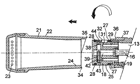
Figure 1 is an exterior elevation of a blind-riveting tool;
CA 02550203 2002-01-21
2
Figures 2A and 2B are respectiveiy an axial section and a cro9s section,
through the
collectlon means and the adjacent part of the tool in the connected condition;
Figures 3A and 3D correspond to Figures 2A and 2B respectively, and show the
6 disconnected condition;
Figures 4A and 4B are exterior top views of the adjacent parts of the
collection means
and tool, illustrating the cam arrangement for assisting initial displacement;
and
Figures 5A and 5B are enlarged sections of the area marked X in Figure 2A,
illustrating the detent action of one of the flexible resiilent members.
The hand-held blind riveting tool is substantially identical to that described
in WO
96/38345, to which the reader is referred for a description of the
construction and
operation of the tool. The present tool includes a pneumatic/hydraulic
intensifier, fed by
compressed air through a hose 11. When an external trigger 12 is pressed, the
intensifier is actuated to drive a head piston along a bore 13 (Figures 2A and
3A) to
cause a jaw-assembly to grip and pull the pin-tail of a blind rivet 14 which
has been
inserted in the nosetip 15 of the tool. The body of the blind rivet deforms,
and
eventually the pin of the rivet breaks and the jaws retract with the broken
off pin-tail.
The jaws release the pin-taii which is ejected rearwardly along a tube 16
which extends
along the centre of bore 13. The tube 16 leads into a bore 43 through a
connector
block 18 which is secured on the rear end of the bore 13.
In order to return the head piston and jaws forwardly when the trigger 12 is
released,
air under pressure is fed all the time along a bore 19 to the bore 13 behind
the piston.
This air pressure feed is also used for other purposes, as will be described
below.
Means for collecting broken off pin-tails Is provided by what is known as a
bottle 21.
This Is substantially cyciindricai, but with a siightly tapering exterior
surface 22. The
rear end of the bottie Is provided with vent holes 23. The major part of the
interior of
the surface of the bottle tapers slightly, but the front part 24 is
cyclindrical. This mates
with the cylindrical exterior face 25 of the connector block 18, there being a
narrow
annular gap 26 between the faces 24 and 25 (Figures 2A, 5A and 5B).
CA 02550203 2002-01-21
3
The connector block 18 carries two flexible resilient sealing members 27 and
28. The
forward most one 27 is an O-ring seal, and the rearward most one 28 is a lip-
seal.
Both seals protrude sufficiently above the surface 25 of the connector block
18 (see
Figure 3A) that when the bottle Is In the connected or secured position shown
in Figure
2A, in which the front end 24 of the bottle 21 is fully forward over the
connector block
18, both seals contact the inner surface of the bottle (as described in detail
below). Air
under pressure from feed bore 19 is fed, by means of the rear part of the bore
13, an
annular gap 29 in the front of connector block 18, a radial bore 31 and a
silencer
chamber 32, to the annular gap 26. The chamber 32 is positioned between the
seals
27 and 28, so that air pressure is applied to both seals. This air pressure
causes both
seals to deform slightly, so as to expand radially to produce enhanced
frictional contact
between the seals and the bottle 21. This substantially increases the force
necessary
to remove the bottle from the connector block, thus effectively securing the
bottle to
the tool.
The forward seal 27 is an 0-ring seal (i.e. of circular cross-section), but
the rearward
seal 28 is a lip-seal, and its action is illustrated in enlarged sections in
Figures 5A and
5B. As shown in these Figures, the rear end of the circular section 24 of the
bottle
interior joins the slightly tapering section behind it by means of a more
steeply sloping
tapered section 33, in which the lip-seal 28 can engage when the bottle is in
the
secured condition (as shown in Figure 2A). This engagement is shown in Figure
5A, in
which the lip-seal is radially expanded by means of the air pressure in
annular gap 26.
This effectively provides a resilient detent engagement between the bottle and
the
connector block.
In order to release this enhanced frictional engagement between the bottle and
the
connector block, It Is necessary to axially withdraw the bottle from the
adapter until the
front end 34 clears the forward seal 27. This needs considerable force, even
after the
initial disengagement of the detent lip-seal from the taper section 33. It is
doubtful
whether a tool operator could apply sufficient force, by hand, by grasping and
axially
pulling at the bottle. Even If he or she could do so, the sudden reduction in
restraining
force, when the front end 34 of the bottle clears seal 27, would very likely
result in the
sudden acceleration of the bottle and the scattering of Its contents out of
its open front-
end, which would be hlghly undesirable.
CA 02550203 2002-01-21
4
Accordingly, means for assisting in the lnitial displacement of the bottle is
provided In
the form of a cam arrangement. As illustrated In Figure 2A, 3A, 4A and 4B, the
front
end 34 of the bottle is formed with a projecting arcuate cam 35 which extends
around
half the circumference of the bottle and is of increased internal radius, so
that it mates
with a corresponding arcuate cam 36 provided on the connector block retaining
ring
37. Figures 2A and 4A show the bottle In the fully engaged position, with the
two cams
35 and 36 aligned. To initially disengage the bottle, the operator grips the
exterior
surface 22 of the bottle 21 and rotates the bottle about its axis. This drives
the cam 35
to force the bottle rearwards with considerable mechanical advantage, until
the front
end 34 of the bottJe clears seal 27 (Figure 4B shows the bottle rotated
through 900,
driving the front end 34 well beyond the seal 27). The deforming air pressure
on the
seals having been vented, completion of removal of the bottie is easily
achieved. After
the bottle has been emptied, its replacement on the connector block is also
relatively
easily achieved, since the operator can more easily apply manual compressive
force to
the end of the bottle to force it forwards over the radially enlarged seals 27
and 28
after the bottle front end 34 has again met and sealed against forward seal
27.
Another feature of the invention is also illustrated in Figures 2A and 3A and
more
particularly in Figures 2B and 3B.
It is known to provide this type of blind-riveting tool with a safety shutter
at the rear end
of the tool body, which is opened when the pin-tail collector bottle is
connected to the
tool, but which closes automatically, under resilient urging, when the bottle
is removed
from the tool. This is a safety device, to prevent ejection of a pin-tail if
the tool is
operated when the bottle is not connected (since the head-piston and jaw-
assembly
are automatically returned by air pressure when the tool trigger is released
after a
riveting operation, if the collector bottie is then removed and the return air
vented, one
further fastener can be installed before the head piston is not retumed
forwards again).
It is known (e.g. in a tool under the name MASTBRFIX, and In certain tools
under the
name HONSEL) to close the safety shutter mechanically by contact of the
bottle, when
in the connected position, with a lever or button which the bottle dispiaces
against a
spring from the shutter-closed position to the shutter-open position. However
It has
been found that It is possible to override such mechanically operated safety
devices by
holding the lever or button in the shutter-open position e.g. by finger-
pressure, by a
wedge, or by the application of, adhesive tape. In order to overcome this, in
the tool of
CA 02550203 2002-01-21
~
this example the shutter is held closed by air pressure which is vented when
the bottle
is removed. Thus the shutter 38 is provided by a rectangular-section plunger
moving
In a rectangular-section transverse bore 39 in the connector block 18. The
shutter 38
has a circular aperture 41, and is urged by a coil spring 42 Into a position
in which the
aperture does not correspond with the pin-taii passage bore 43 axially through
the
adapter, i.e. the closed position. The shutter is held in its open position,
in which the
aperture 41 is aligned with the passage 43, by air pressure applied at the end
of the
bore 39 remote from the spring 42. This is achieved by the means of a short
radial
bore 44 which connects the end of the bore 39 to the exterior surface of the
connector
block and thus to the annular gap 26 to which air pressure is fed as
previously
described. When the bottle is in the fully connected and retained position
(Figure 2A),
the air pressure in the ar-nular gap 26 holds the shutter open (Figure 2B). As
soon as
the bottle is axially withdrawn sufficiently for its front end 34 to clear the
front seal 27,
the air pressure is vented and the shutter closes (Figure 3B). The only way in
which
the shutter could be held closed while the bottle is not connected would be to
apply
and maintain sufficient air pressure to the radial bore 44, which would in
practice be
very difficult.
An advantage of the tool of the foregoing example is that pin-tail ejection is
prevented
as soon as the bottle 22 is unlocked from the tool when the seal 27 is
released.
The invention is not restricted to the details of the foregoing example. For
instance,
although it Is convenient to use the same air pressure application and
automatic
venting arrangement to actuate both the bottle retention feature, and the
shutter
closure feature, either feature could be used without the other.
The lip-seal 28 could be substituted by, for example, an 0-ring seal similar
to the one
27, but with lowered bottle retention force.
The shutter closing spring 42 could be substituted, for example, by air
pressure.