Note: Descriptions are shown in the official language in which they were submitted.
CA 02550472 2010-08-12
-1-
Title: Display Assembly for Kinetic Artwork
Field of the Invention
[0001] Embodiments of the invention relate generally to the field of
displays for artistic works and more particularly to the display of three-
dimensional artworks.
Background of the Invention
[0002] Displays that are shaped in a pleated or accordion-style manner
can be used to display multiple images, where the image seen by the viewer
depends on the position of the viewer. Such artwork images are often called
kinetic artwork or kinetic artwork images, and are generally discussed in the
United States Patent No. 6,306,479.
Summary of the Invention
[0003] In accordance with an aspect of the invention, there is provided
a display assembly comprising; (a) an image insert, the image insert being
bendable from a planar configuration to a non-planar display configuration,
wherein the image insert comprises a plurality of first surfaces for
displaying a
first image, and a plurality of second surfaces for displaying a second image;
and (b) a display frame for supporting the image insert in the non-planar
display configuration. The display frame comprises an abutment structure for
abutting the plurality of first surfaces and the plurality of second surfaces
to
secure the plurality of first surfaces at a non-zero angle relative to the
plurality
of second surfaces and to resist unbending of the image insert.
[0004] In accordance with a second aspect of the invention, there is
provided a book comprising (a) a plurality of pages, each page in the
plurality
of pages having a spine edge and a free edge opposite to the spine edge; (b)
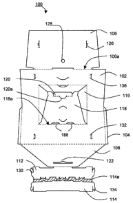
a spine for securing the plurality of pages together, the spine being attached
to the spine edge for each page in the plurality of pages; (c) an image insert
for displaying a first image and a second image, the image insert being
bendable from a planar configuration to a non-planar display configuration,
wherein the image insert comprises a plurality of first surfaces for
displaying a
CA 02550472 2006-06-19
-2-
for displaying a first image and a second image, the image insert being
bendable from a planar configuration to a non-planar display configuration,
wherein the image insert comprises a plurality of first surfaces for
displaying a
first image, and a plurality of second surfaces for displaying a second image;
and (d) a display frame for supporting the image insert in the non-planar
display configuration. The display frame comprises an abutment structure for
abutting the plurality of first surfaces and the plurality of second surfaces
to
secure the plurality of first surfaces at a non-zero angle relative to the
plurality
of second surfaces and to resist unbending of the image insert. Before
assembly, the image insert is detachably attached to one of the spine and at
least one page in the plurality of pages in the planar configuration; and the
display frame is detachably attached to one of the spine and at least one
page in the plurality of pages
Brief Description of the Drawings
[0006] For a better understanding of embodiments of the invention, and
to show more clearly how they may be carried into effect, reference will now
be made, by way of example, to the accompanying drawings in which:
[0007] Figure 1 is a front perspective view of an assembled display
frame for use with a kinetic artwork insert according to one embodiment of the
invention;
[0008] Figure la is a rear perspective view of the assembled display
frame of Figure 1;
[0009] Figure 2 is a plan view of the unassembled display frame of
Figure 1;
[0010] Figure 2a is a plan view of a kinetic artwork insert in a planar
configuration for use with the display frame of Figure 1;
[0011] Figure 2b is a plan view of a portion of the display frame of
Figure 2 showing two band members;
[0012] Figure 3 is a perspective view of the assembled display frame of
Figure 1 with the kinetic artwork insert of Figure 2a;
CA 02550472 2006-06-19
-3-
[0013] Figure 4 is a front view of the assembled display frame and the
kinetic artwork insert of Figure 3;
[0014] Figure 4a is a bottom view of the assembled display frame and
the kinetic artwork insert of Figure 3;
[0015] Figure 5 is a perspective view of the display frame of Figure 1
shown partially assembled;
[0016] Figure 6 is a plan view of an unassembled display frame with a
kinetic artwork insert according to one embodiment of the invention;
[0017] Figure 7 is a plan view of an unassembled kinetic artwork insert
according to another embodiment of the invention;
[0018] Figure 7a is a plan view of an unassembled display frame for
use with the kinetic artwork insert of Figure 7;
[0019] Figure 7b is an exploded perspective view of a book with the
display frame of Figure 7a and the kinetic artwork insert of Figure 7
attached;
[0020] Figure 8 is a perspective view of a display frame having a
supporting insert according to another embodiment of the invention;
[0021] Figure 8a is a perspective view of a kinetic artwork insert for
mounting on the supporting insert of Figure 8;
[0022] Figure 9 is a perspective view of the kinetic artwork insert of
Figure 8a mounted to the display frame of Figure 8;
[0023] Figure 9a is a bottom view of the kinetic artwork insert and
display frame shown in Figure 9;
[0024] Figure 10 is a perspective view of a display frame according to
another embodiment of the invention;
[0025] Figure 10a is a side view of a section of the display frame of
Figure 10; and
[0026] Figure 10b is a top view of a section of the display frame of
Figure 10.
CA 02550472 2006-06-19
-4-
Detailed Description
[0027] Aspects of the invention involve a display assembly comprising
an image insert, the insert being bendable from a planar configuration to a
non-planar, or accordion-like, configuration. The image insert has a number of
first and second surfaces for displaying portions of a first image and
portions
of a second image respectively. The display assembly further comprises a
display frame for supporting the image insert in the non-planar configuration.
The display frame, in turn, includes an abutment structure for abutting the
first
and second surfaces to secure the first surfaces at a non-zero angle relative
to the second surfaces. The abutment structure resists the image insert
unbending and returning to the planar configuration.
[0028] In some embodiments, the image insert has a number of fold
lines defining alternating first and second surfaces, wherein each of the
first
surfaces is adjacent to and separated from a second surface by a fold line.
[0029] In one embodiment, the abutment structure comprises a pair of
curved bands connected to an upright member of the display frame. At least
one of the bands has a series of abutments, such as notches or tabs, spaced
along the band to secure the image insert to the display frame, and to keep
the image insert in its non-planar configuration. Specifically, the notches
and
tabs are arranged to ensure that the first and second surfaces remain at the
non-zero angle relative to each other to ensure optimum viewing for a viewer.
In some preferred embodiments, this non-zero angle will be approximately 90
degrees.
[0030] Other embodiments of the invention involve a book having a
plurality of pages. Each page has a spine edge and at least one free edge.
The spine edge is attached to the spine of the book to secure the pages
together. An image insert, in a planar configuration, is attached by a spine
edge to the spine of the book. A display frame is also attached to the spine
of
the book using a spine edge. The image insert and display frame are
removable to provide a display assembly.
CA 02550472 2006-06-19
-5-
[0031] Features of various embodiments of the invention are discussed
in greater detail below with reference to the appended figures.
[0032] With reference to Figure 1, Figure la and Figure 2, an
assembled display frame 100 comprises an upright member 102 having
support fins 104, an upper support 106, a base member 108, and an opening
110 cut through the center of the upright member 102. Two curved abutment
bands, lower band 112 and upper band 114, are attached to the upright
member 102 at a lower and upper portion respectively. The display frame 100
further comprises center support flaps 116 that fold away from the upright
member 102 along fold lines 116a, and a rear support flap 118 connected to
the upright member 102 along fold line 118a.
[0033] The base member 108 sits on a ground surface to support and
hold the upright member 102 in a substantially vertical position relative to
the
ground surface. The support fins 104 provide additional support, protruding
off
the sides of the upright member 102 at a generally non-zero angle and
extending vertically to provide additional rigidity to prevent the display
frame
100 from tipping. In one preferred embodiment, the angle between the
support fins 104 and the upright member 102 is about 45 degrees. In another
embodiment, this angle is approximately 90 degrees.
[0034] The rear support flap 118 provides additional support for
spacing the upright member 102 from the base member 108. When
assembled, the rear support flap 118 is engaged with the base member 108
by a tab 120 fitted into a keyhole 122 in base member 108. The base member
108 and rear support flap 118 form a generally triangular shape with the
upright member 102 to space the upright member 102 from the base member
108.
[0035] The upper support 106 provides additional rigidity to the upright
member 102. The upper support 106 is attached to the upright member 102 at
fold edge 106a, and is supported by the center support flaps 116 by
engagement of tabs 124 with slots 126, providing increased rigidity. The
upper support flap 106 may also contain a mounting hole 128 which can be
CA 02550472 2006-06-19
-6-
used to mount the display frame 100 on a vertical surface, for example by
placing a hook through the mounting hole 128.
[0036] Images, for example those images complementing the kinetic
artwork insert, advertising images, or a calendar, may be printed on one or
more portions of the display frame such as the upright member 102, the rear
support member 118 and the upper support 106. In this fashion, the display
frame 100 may be made more aesthetically pleasing to the viewer, or can be
used for a secondary purpose, for example, by displaying a calendar on the
upright member 102.
[0037] As shown, the lower band 112 and upper band 114 are
contoured and curve outwards somewhat from the plane of the upright
member 102. The lower band 112 provides a lower mount for the kinetic
artwork insert 140 (as shown in Figure 3). The lower band 112 is joined to
upright member 102 by inserting tabs 130 into slots 132 in the upright
member 102. The lower band 112 preferably contacts the ground surface,
helping to support the upright member 102 in its substantially vertical
position.
The upper band 114 is similarly connected to the upright member 102 using
tabs 134 engaged with slots 136 (shown in detail in Figure 5) to provide an
upper mount for the kinetic artwork insert 140.
[0038] The opening 110 in the upright member 102 allows for ambient
light to pass through the display frame 100, to create a halo effect around
the
kinetic artwork insert 140, highlighting the images. Alternatively, in some
embodiments an electric light or a candle may be mounted on or to the rear
support flap 118 or base member to provide additional illumination through the
opening 110. In some embodiments, a sound chip may be mounted to the
base member 108 to provide music, speech or other sound-based
accompaniment while viewing the image.
[0039] The display frame 100 is made from a resilient planar material,
such as a thin sheet of cardboard. In some embodiments, the display frame
can be made from materials such as plastic or foam sheet, cardstock, heavy
CA 02550472 2006-06-19
-7-
paper or other suitably resilient materials. In one preferred embodiment, the
display frame is made from a 20-point SBS cardboard.
[0040] With specific reference to Figure 2, the display frame 100 is
visible in a planar configuration before assembly. As shown, the lower band
112 and upper band 114 are initially joined to the display frame 100. The
lower band 112 and upper band 114 are held together by a removable
connecting piece 114a, and are connected to the base member 108 at a tear-
off connection 112a. To assemble the display frame 100, the lower band 112
and upper band 114 are detached from the base member 108 by tearing
along the tear-off connection 112a. The connecting piece 114a is removed,
and the lower band 112 and upper band 114 can then be inserted into the
upright member 102.
[0041] Turning now to Figure 2a, the kinetic artwork insert 140 is shown
in its planar configuration as a thin, rectangular section of a resilient
material.
The kinetic artwork insert 140 has a series of fold lines 142; folding along
the
fold lines 142 gives the kinetic artwork insert 140 its distinctive accordion-
style
or non-planar display configuration. In some embodiments, one or more of the
fold lines 142 may include perforations to provide for easier folding. In
other
embodiments, the fold lines may simply be scored without perforating the
material.
[0042] The kinetic artwork insert 140 comprises a series of alternating
first image surfaces 144 and second image surfaces 146. The first image
surfaces 144 comprise sections or strips from a first image, and the second
image surfaces 146 comprise sections or strips from a second image. When
the kinetic artwork insert 140 is folded into its non-planar display
configuration, an observer will observe what appears to be the first image
when viewing from a first location, and will observe what appears to be the
second image when viewing from a second location.
[0043] In some embodiments, the kinetic artwork insert 140 is made of
a material such as cardboard, cardstock or paper. In one preferred
CA 02550472 2006-06-19
-8-
embodiment, the cardboard is 10-point SBS cardboard. In another preferred
embodiment, the cardboard is 12-point SBS cardboard.
[0044] In some embodiments, the kinetic artwork insert 140 is pre-
printed with an images, such that the sections from the first and second
images are printed onto the corresponding first image surfaces 144 and
second image surfaces 146 respectively. In other embodiments, the kinetic
artwork insert 140 may be blank, and a user can populate the image surfaces
144, 146 using pre-cut or 'kiss-cut' stickers shaped to match the image
surfaces 144, 146. In some embodiments, sheet of stickers may have the first
and second images pre-printed thereon. In other embodiments, the sheet of
stickers may be blank, and the user may draw, paint, or print first and second
images onto the stickers before placing them onto the kinetic artwork insert
140. For example, the stickers may be provided on a 'kiss-cut' photo-paper,
which can used to print first and second images using a standard inkjet
printer, and then placed onto the kinetic artwork insert 140, maintaining the
order of the strips so that the first and second images maintain the proper
viewing relationship.
[0045] Turning now to Figure 2b, the upper band 114 and the lower
band 112 from Figure 2 are shown in greater detail. The upper band 114 and
the lower band 112 are joined by the connecting piece 114a along tear lines
114b and 114c. The lower band 112 is also connected to the base member
108 of the display frame 100 at the tear off-connection 112a. As discussed
above, the upper and lower bands 112, 114 must be torn away from the base
member 108 of the display frame 100 at the tear-off connection 112a, and the
connecting piece 114a removed, before the lower band 112 and upper band
114 can be mounted to the upright member 102.
[0046] The tabs 130 on the lower band 112 and the tabs 134 on the
upper band 114 can be seen in greater detail in Figure 2b, and are shaped to
engage with the slots 132 and 136 on the upright member 102. The lower
band 112 also comprises a plurality of notches 148, rear tabs 150 and front
tabs 151. The notches 148, rear tabs 150 and front tabs 151 are shaped and
CA 02550472 2006-06-19
-9-
spaced along the lower band 112 to engage and secure the lower edge of the
kinetic artwork insert 140 during assembly, and to ensure it maintains its non-
planar or accordion-style shape, while staying flush with the upright member
102. Specifically, vertical sections of the kinetic artwork insert 140 are
inserted
into the notches 148, while the rear tabs 150 support from the rear of the
kinetic artwork insert 140 and the front tabs 151 support from the front of
the
kinetic artwork insert 140. In the preferred embodiment, the notches 148 are
generally U-shaped with walls that accommodate kinetic artwork inserts 140
of different thicknesses, or engage multiple kinetic artwork inserts 140
concurrently. The front tabs 151 may have v-shaped grooves 151a cut out to
provide improved viewing of the kinetic artwork insert 140 when mounted on
the display frame 100, and to improve the aesthetic appearance of the display
frame 100.
[0047] The upper band 114 optionally has teeth members 152 for
engaging with and securing an upper edge of the kinetic artwork insert 140 to
the display frame 100. The teeth members 152 on the upper band 114 are
sized and spaced to secure the kinetic artwork insert 140 to the display
frame,
and to help the kinetic artwork insert 140 maintain its non-planar display
configuration when inserted into the display frame 100.
[0048] Turning now to Figure 3, Figure 4 and Figure 4a, the display
frame 100 is shown assembled with kinetic artwork insert 140 in its non-planar
display configuration. The kinetic artwork insert 140 sits in the notches 148
on
the lower band 112, and is secured in place by the front tabs 151 which are
visible and shown in solid lines, and the rear tabs 150, which are hidden and
are shown in dashed lines. The teeth members 152 on the upper band 114
are shown engaged with the folds in the kinetic artwork insert 140.
[0049] In Figure 4a, the position of the kinetic artwork insert 140 with
respect to the lower band 112 is shown in detail. The first image surfaces 144
and the second image surfaces 146 are oriented at angle 0 relative to each
other. In a preferred embodiment, the angle 0 between the first image surface
CA 02550472 2006-06-19
-10-
144 and the second image surface 146 is approximately 90 degrees to
provide optimum viewing of the first and second images.
[0050] It is also desirable that the kinetic artwork insert 140 stay flush
against the upright member 102 and not follow the curve of the lower band
112, as this ensures a better quality of image to the observer. It is also
desirable that the angle 0 be optimized for viewing. This is accomplished by
properly selecting the size and spacing of the notches 148, the rear tabs 150
and front tabs 151 on the lower band 112. For example, with reference to
Figures 4 and 4a, a first front tab 151a would have spacing 'd1' as shown at
one end of the lower band 112, and a second front tab 151b would have
spacing 'd3' as shown at the centre of the lower band 112. A third
intermediate spacing is shown as 'd2'. Generally, 'd2' is slightly larger than
'dl', and 'd3' is slightly larger than 'd2', helping the kinetic artwork
insert 140 to
stay flush to the upright member 102 while accommodating the curvature of
the lower band 112. It will be appreciated by those skilled in the art that
the
particular sizes and spacing of 'dl', 'd2' and 'd3' will depend upon the
curvature of the lower band 112, as well as the particular size and shape of
the kinetic artwork insert 140.
[0051] Figure 4a also clearly shows the tab 120 of the rear support flap
118 engaged with the keyhole 122 of the base member 108, securing the rear
support flap 118 to the base member 108. In some embodiments, such as the
embodiment shown in Figure 4a, a secondary tab 120a may be used to help
secure the tab 120 to the base member 108. The tabs 120 and 120a project in
opposite directions against the base member 108 thereby reducing the
chance of inadvertent removal of tabs 120 and 120a from the keyhole 122.
[0052] In Figure 5, the tabs 134 of the upper band 114 have been
inserted into the slots 136 on the upright member 102, securing the upper
band 114 to the upright member 102. The lower band 112 is partially secured
to the upright member 120, and tab 130a is being inserted into slot 132a to
completely secure the lower band 112 in place.
CA 02550472 2006-06-19
-11-
[0053] Turning now to Figure 6, the display frame 100 and kinetic
artwork insert 140 of Figure 2 have been prepared to use as an insert, for
example in a plastic bag holding a magazine. In step 1, the kinetic artwork
insert 140 is placed onto the upright member 102 of the unassembled display
frame 100. In step 2, the base member 108 is then folded over to partially
cover the kinetic artwork insert 140. In step 3, the upper support 106 is
folded
over to cover the base member 108 and the kinetic artwork insert 140. In this
manner, the kinetic artwork insert 140 is protected by the folded base member
108 and upper support 106 of the display frame 100, and the entire assembly
can be easily inserted into a plastic bag for distribution with a magazine,
for
example.
[0054] Figure 7 and 7a show a different embodiment of the invention
for use as a detachable part of a book or magazine. For clarity, the same
reference numerals are used to designate elements analogous to those
described above in connection with Figures 1 to 5. The kinetic artwork insert
140 is included as part of an insert sheet 160 in such a way that it can be
easily detached by providing perforated cut lines along the edges of the
kinetic artwork insert 140. The upper band 114 and a lower band 112 are also
included in the insert sheet 160 in a similar manner, and are easily removed.
The kinetic artwork insert 140 shown in Figure 7 has different types of
parallel
fold lines, included scored fold lines 142a, and perforated fold lines 142b.
For
the scored fold lines 142a, the sheet material of the kinetic artwork insert
140
has been creased but has not been perforated, while the perforated fold lines
142b comprise a series of cuts or holes passing through the material of the
kinetic artwork insert 140. The combination of scored fold lines 142a and
perforated fold lines 142b provides for improved folding.
[0055] The image sheet 160 is designed to be attached to a book or a
magazine, using a spine edge 162, which is connected to the insert sheet 160
along tear line 164.
[0056] The display frame 100 shown in Figure 7a is similarly included
as part of a frame sheet 166, and the display frame 100 is provided with
CA 02550472 2006-06-19
-12-
perforated cut lines along the edges to allow for easy removal. In this
particular embodiment, the display frame 100 comprises generally an upright
member 102 and a base member 108, with rear support flap 118, but has no
upper support. Optionally, however, the frame sheet 166 may include an
upper support 106.
[0057] The frame sheet 166 is designed to be attached to a book or
magazine, using a second spine edge 168, which is connected along tear line
170.
[0058] As shown in Figure 7b, the spine edges 162, 168 are joined with
other pages in a book or magazine 172 using a typical binding process, for
example by gluing or by stapling, to secure the image sheet 160 and the
frame sheet 166 as part of the magazine 172. In one embodiment, the frame
sheet 166 and image sheet 160 can be made from one large sheet, and be
stapled at the centre of a book or magazine.
[0059] During assembly, the frame sheet 166 and image sheet 160 are
removed from the book or magazine along the tear lines 164, 170. The
individual components such as the display frame 100 can then be removed
using the perforated cut lines, and assembled. It will be appreciated that the
shapes and sizes of the image sheet 160 and the frame sheet 166 may be
adjusted to accommodate books and magazines of different shapes and
sizes.
[0060] In some embodiments of the invention, the book or magazine
may include one or more sticker sheets having one or more images, which
can be peeled off and mounted onto the kinetic artwork insert.
[0061] Figure 8, 8a, 9 and 9a show yet another embodiment of the
invention. For clarity, the same reference numerals are used to designate
elements analogous to those described above in connection with Figures 1 to
7b. As shown in Figures 8 and 8a, a shaped insert 180 is used to support the
kinetic artwork insert 140 on the display frame 100. The shaped insert 180
resists deformation to support the kinetic artwork insert 140 in the non-
planar
CA 02550472 2006-06-19
-13-
or accordion-like configuration. In one embodiment, the shaped insert 180 is
molded. The insert 180 has an upper tab 182 and a pair of lower tabs 184, for
engagement with an upper slot 186 and a pair of lower slots 188, respectively,
on the display frame 100. The insert 180 further comprises a series of peaks
190 and valleys 192, generally at angle 0 relative to each other, and spaced
to engage with the kinetic artwork insert 140 when in its non-planar display
configuration.
[0062] In this embodiment, the insert 180 replaces the upper and lower
bands 112, 114 in the above-described embodiments, secures the kinetic
artwork insert 140 to the display frame 100, and ensures the kinetic artwork
insert 140 remains in its non-planar display configuration. In some
embodiments, the kinetic artwork insert 140 is releasably attachable to the
insert 180 to allow different kinetic artwork inserts 140 to be used with the
same insert 180. In some embodiments, the kinetic artwork insert 140 may be
secured to the insert 180 using tape, sticky wax, or some other releasable
means. The kinetic artwork insert 140 may also be glued to the insert 180 to
provide a more permanent bond.
[0063] The insert 180 is preferably made from a generally light-weight,
rigid material, for example a lightweight plastic or foam, cardboard or paper,
or any other suitable material, such that it can secure the kinetic artwork
insert
140 in its non-planar form to the upright member 102 without causing the
display frame 100 to tip.
[0064] With reference specifically to Figure 9a, peaks 190 and valleys
192 of the insert 180 are clearly shown, engaged with the first image surfaces
144 and second image surfaces 146 on the kinetic artwork insert 140 to
project the kinetic artwork insert 140 away from the upright member 102. In
this fashion, the kinetic artwork insert 140 appears to the viewer to float in
front of the upright member 102 while still maintaining the non-planar display
configuration that facilitates perception of the first and second images by a
viewer. In addition, a shadow 194 may be created around the kinetic artwork
insert 140, which can further emphasize the images. Further, light passing
CA 02550472 2006-06-19
-14-
through the opening 110 in the display frame 100 may create a halo effect
around the kinetic artwork insert 140, further highlighting the images.
[0065] Turning now to Figures 10, 10a and 10b, there is illustrated a
display frame 200 designed for use with the insert 180 discussed above,
according to another embodiment. The display frame 200 comprises an
upright member 202 having a generally curved shape such that no base
member is needed to support the upright member 202 in an upright position,
as best seen in Figure 10b. Support fins 204 may optionally be present to
provide additional stability.
[0066] The display frame 200 has a flat region 206, having an upper
hook 208 and a pair of lower hooks 210, spaced and arranged to engage with
the upper tab 182 and the lower tabs 184 on the insert 180. Thus, a kinetic
artwork insert 140 can be mounted to display frame 200 using the insert 180.
[0067] The display frame 200 is made of a generally rigid material,
such as a hard plastic or a metal. In preferred embodiments, the display frame
200 is made from a brushed aluminum or a stainless steel.
[0068] The invention has been described with regard to a number of
embodiments. However, it will be understood by persons skilled in the art that
other variants and modifications may be made without departing from the
scope of the invention as defined in the claims appended hereto.