Note: Descriptions are shown in the official language in which they were submitted.
CA 02550555 2008-08-07
COVER ASSEMBLY FOR AN ELECTRICAL FLOOR BOX
BACKGROUND OF THE INVENTION
[0002] This invention pertains to floor boxes which house power and
communication wires for termination and, more particularly, to a cover
assembly
having a smaller cord door that can be re-positioned as needed.
[0003] It is well-known to run electrical wires and telecommunications wires
underneath the surface of a floor. These cables and electrical systems may be
placed
under the floor surface so as to be more efficient in supplying power and
dataltelecommunication signals in commercial buildings. The electrical cables
or wires
beneath the floor may be accessed through a hole in the surface of the floor.
In order to
provide convenient access to the wires or cables as well as the termination
devices
which terminate the wires, a floor box is typically placed in the hole through
the floor.
[0004] Floor boxes are typically made of metallic material so that they are
resistant
to the outside elements, such as moisture, and are also strong enough to
maintain the
structural integrity of the floor. The cover used on these floor boxes
oftentimes varies
depending on the type of flooring to be employed, i.e. wood, tile, exposed
concrete, and
the like. Such covers oftentimes incorporate a smaller cord door that is used
after the
building is completed in order to allow wires to extend from the floor box
through the
cord door and to the device being powered or communicated with.
[0005] However, during construction, the exact placement of such devices is
not
known. Thus, it is common to find the cord door in an inconvenient/improper
orientation following the installation process. Also, once the building is
completed, it is
quite common for the building layout to change over time and thus these
powered or
communicated devices will be moved to yet another location. Thus, the cover on
these
CA 02550555 2006-06-14
floor boxes will need to be adjusted once again to take into account the new
location of
these devices. Further, it is common for the building layout to require a new
or different
type of cover to be employed, such as one requiring connection to a flexible
conduit.
Hence the floor box and/or its cover may need to be altered accordingly.
[0006] In the past, when such a situation was encountered, it became necessary
for
the entire cover of the embedded floor box to be separated from the box. The
cover
would then be rotated (if possible) so as to properly position the smaller
cord door to
open in the desired direction. This required the removal of the flooring
material
surrounding the floor box (and oftentimes beyond) so that the fasteners
securing the
cover to the box could be accessed. In some cases, concrete had to be removed
if the
pour extended over these fasteners. Also, removal and replacement of this
flooring
material is costly and hence, in many situations, the cost and effort of re-
positioning the
cover was not deemed worth the effort.
[0007] Also, even if worth the effort of re-positioning the cover, some boxes
may
not pennit this because the cover may only be secured to the box in one
orientation.
Alternatively, the box may not be square and hence the cover may only be able
to be
rotated 180 degrees and not 90 degrees which may be the desired cord door
opening
direction. Furthermore, even if the box is of some other shape that can
accommodate a
rotatable cover, the fastener locations may not be in alignment so that even
if the box
can accommodate a re-positioned cover, the fasteners cannot.
[0008] Regardless of the need required of the floor box and its cover, the
design
must also be adequate enough to support the weight and loading that a typical
floor box
is subject to and the floor box assembly must still comply with all local and
national
codes and or specifications pertaining to floor boxes.
[0009] It is thus an object of this invention to provide a floor box cover
that
incorporates a smaller cord door therein. Another object of this invention is
to provide
a floor box that complies with all local and national codes and
specifications. A further
-2-
... .... ,...r .. ... , , .. ~s,.,.,. _õ
. _.. ... . . r,. .k ....r.+e.WM. r ..a-I. rvr... Arr . .... 1. . .
CA 02550555 2006-06-14
object of this invention is to provide a floor box with a cord door such that
the cord door
can be adjusted so as to open in the desired direction without having to re-
position or
re-orient the entire cover. Still another object of this invention is to
provide a cord door
that can be removed and re-positioned as needed and further that can be
replaced with
another different cover plate if the need to do so arises. These and other
objects and
advantages of this invention will become evident upon further review.
SUMMARY OF THE INVENTION
[0010] The present invention, which addresses the needs for the prior art,
relates to
a cover assembly for a floor box. The cover assembly includes an access door
for
covering at least a portion of the floor box. The access door includes an
opening for
passage of at least one cord therethrough. The cover assembly further includes
a cord
door positioned to cover the opening in the access door. The cord door is
removeably
securable to the access door in at least two mounting orientations.
[0011] Additionally, the cord door can be pivotally secured to said access
door, as
well as including a locking mechanism for securing the cord door in an open
position.
The locking mechanism can include a biasing element to resist pivoting the
cord door
when the cord door is in the open position. Also, the cover assembly can
further include
an cord door frame secured to the perimeter of the opening in the access door
and
supporting the cord door. This cord door frame can include a plurality of
fastening
openings that align with respective openings on the access door for securing
the cord
door frame in at least one of the mounting orientations. Alternatively, the
cord door
itself can include a plurality of fastening openings that align with
respective openings
on the access door for securing the cord door in at least one of the mounting
orientations.
Further still, the cover assembly can include a frame secured to at least a
portion of the
floor box, with the access door supported by this frame. The access door can
be
pivotally secured to the floor box.
[0012] The present invention further relates to that portion of a cover
assembly for a
floor box that includes a cord door positioned over at least a portion of the
floor box.
-3-
. . , .... rvwr._.....:w -,... ..~I .,.i- ..õ r . . . , .
CA 02550555 2008-08-07
The cord door pivotally mounts to rotate between a closed position and a first
open
position. The cover assembly also includes a locking mechanism secured to the
cord
door. The locking mechanism selectively retains the cord door in a second open
position.
[0013] Additionally, the locking mechanism can include a biasing element to
resist
pivoting of the cord door when the cord door is in the second open position.
Also, the
locking mechanism can include a button engaged with the biasing element.
Movement
of the button causes movement of the biasing element to counter the resistance
of the
biasing element to allow pivoting of the cord door.
[0013.1] In accordance with one aspect of the present invention, there is
provided a cover assembly for a floor box, comprising: an access door covering
at least a portion of said floor box, said access door being pivotally mounted
with respect to said floor box, said access door including an opening for
passage
of at least one cord therethrough; and a cord door positioned to cover said
opening in said access door, said cord door being removeably securable to said
access door in at least two mounting orientations, wherein said mounting
orientations are rotationally offset from one another about an axis
perpendicular
to said opening.
[0013.2] In accordance with another aspect of the present invention, there is
provided a cover assembly for a floor box, comprising: an access door covering
at least a portion of said floor box, said access door including an opening
for
passage of at least one cord therethrough; and a cord door positioned over at
least a portion of said opening, wherein said cord door is removeably secured
to
said access door in more than two mounting orientations, wherein said mounting
orientations are rotationally offset from one another about an axis
perpendicualr
to said opening.
-4-
CA 02550555 2008-08-07
[0014] These and other objectives, features, and advantages of this invention
will
become apparent from the following detailed description of illustrative
embodiments
thereof, which is to be read in connection with the accompanying drawings.
BRIEF DESCRIPTION OF THE DRAWINGS
[0015] Fig. I is a perspective view showing the door assembly of the present
invention exploded away from a floor box and with both the cover and cover
door in a
fully closed position.
[0016] Fig. 2 is a view similar to Fig. 1 with both the cover and cord door
shown in
an open position and with cords extending therefrom.
[0017] Fig. 3 is a perspective view of the cover assembly of the present
invention
shown with cords extending therefrom.
[0018] Fig. 4 is a side view of the cover assembly of Fig. 3 without the
cords.
[0019] Fig. 5 is a bottom view of the cord door of Fig. 3 without the cords.
[0020] Fig. 6 is an exploded perspective view of the cord door components.
-4a-
CA 02550555 2008-08-07
[0021] Fig. 7 is a bottom perspective view of the cord door of the present
invention
in an open position.
[0022] Fig. 8 is an exploded perspective view of the present invention showing
the
cord door component separate from the cover component.
[0023] Fig. 9 is an exploded perspective view of an alternate cord door of the
present invention.
[0024] Fig. 10 is an exploded perspective view of another alternative cord
door of
the present invention.
[0025] Fig. 11 is an exploded perspective view of still another alternative
cord door.
DETAILED DESCRIPTION OF THE PREFERRED EMBODIMENT
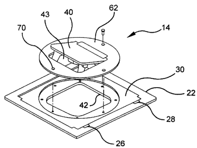
[0026] Referring initially to the drawings, Figs. 1 and 2 show a floor box
assembly
including a floor box 12 and a cover 14. Floor box 12 may be of standard or
typical
construction or floor box 12 may be constructed as shown in Figs 1 and 2 which
is
described in more detail in U.S. Patent No. 7,157,643, entitled "Floor Box
with Voltage
Divider," commonly assigned to Thomas & Betts International, Inc.
[0027] As should be noted, floor box 12, no matter what its construction, is
designed to be mounted in a floor 16 of a building so as to provide access to
power or
communication wires extending through duct or conduit or the like extending
within
the floor. Such wiring is, in the normal fashion, mounted to receptacles,
fixtures,
terminals, jacks or the like that are in turn supported via plates 18 within
floor box 12.
[0028] Cover 14 has a substantially planar surface or appearance 20 when in
the
fully closed position as shown in Fig. 1. Cover 14 is shown in an open
position in Fig.
2. Cover 14 would preferably include an exterior flange 22 that is sized and
configured
to mate with floor box 12, hence the shape of flange 22 is likely to vary
depending on
the floor box 12 used. Typically, one side region of flange 22 is configured
with a hinge
-5-
. . ......, .r..ra .M .....õ,...w+ r A N..t....IN arv . x r I , CA 02550555
2006-06-14
assembly 24 while another opposite side region of flange 22 is configured with
an
opening assembly 26. Both hinge assembly 24 and opening assembly 26 can be of
typical construction, such as a pin and socket arrangement for hinge assembly
24 and
detents or recesses 28 for the opening assembly 26.
[0029] Within flange 22 of cover 14 is access door 30. This access door 30
pivots
on hinge assembly 24 and it is opened via opening assembly 26, 28. Hence, a
user may
operate access door 30 such as by placing a tool within detents or recesses 28
and prying
upwardly. It may also be desirable for access door 30 to incorporate some type
of
retention mechanism 32, such as a ball and spring assembly, so as to retain
access door
30 in the closed position.
[0030] As shown in Fig. 1, when access door 30 is in the closed position, it
is
ideally flush with flange 22. However, as shown in Fig. 2, when access door 30
is in the
open position, access to the interior 34 of floor box 12 is provided. Thus,
access door
30 enables a user to plug and un-plug a wire 38 from its associated terminal
mounted in
plates 18. Also, depending on the configuration of floor box 12, access door
30 may
also enable a user to re-configure or re-wire the interior 34 of floor box 12
to add or
subtract power or communication fixtures. However, such reconfiguration is
preferably
accomplished when floor box 12 is initially being constructed and wired.
[0031] Also shown in the drawings is cord door 40 that is located within the
interior
of frame 62 which is itself located within the interior of access door 30.
Cord door 40
may be centrally located therein or it may be positioned off center, depending
on the
style preferred. In any event, access door 30 is configured with an opening 43
therein
that accommodates cord door 40. Hence, cord door 40 provides separate and
independent access to the interior 34 of floor box 12.
[0032] Cord door 40, when pivoted open as shown in Figs. 2 and 3, permits
wires
38 to extend from or into floor box 12. Locking mechanism 44 is employed to
keep
cord door 40 from collapsing upon or crimping wires 38 when they pass through
-6-
. .........yi, . _i...w..w..., . .N...o j.......i..iwõ,,, . . . , i.
. .... .,,..... ,.nk-..+.m.wx+Fin....nLur..m.I+l.-w...r...rd
CA 02550555 2006-06-14
opening 43. Locking mechanism 44 preferably incorporates a brace 46, as shown
in Fig.
6, having detents or notches 48 at its distal end regions that fit around the
perimeter of
opening 43. Alternatively, the perimeter of opening 43 may include latches 50
that
mate with notches 48 when cord door 40 is opened.
[0033] It should be understood that different configurations are equally
likely for
locking mechanism 44. As shown herein, brace 46 is biased by spring 52 to
always
pivot outwardly or to encourage notches 48 to enter into the engaged position
with the
perimeter of opening 43 or with latches 50. This can only occur when cord door
40 is
opened. Once engaged, however, brace 46 can be disengaged by overcoming the
bias of
spring 52. Such disengagement is achieved by pivoting the button region 54 of
brace 46
against the bias of spring 52. A tool can be inserted to overcome the bias of
spring 52 or
a user can reach one or more fingers underneath cord door 40 and push against
spring 52.
As shown in this embodiment, brace 46 pivots on hinge 56 so it is readily
apparent how
brace 46 can become automatically engaged and how it can be manually
disengaged.
[0034] Now, such disengagement of cord door 40 may be desired to either cause
it
to close and be generally flush with access door 30 or it may be desirable to
disengage
cord door 40 completely so that it can be more fully opened as shown in Fig.
2. This
latter position is useful when passing wires 38 through opening 42 in access
door 30.
The normal operating or locked open position of cord door 40 however is shown
in Fig.
3, wherein brace 46 is employed to keep cord door 40 partially open and locked
in place
thereby permitting wires 38 to pass.
[0035] Referring once again to Fig. 6, preferably cord door 40 pivots about
hinge
pin 60 that is retained within frame 62 via cover plate 64. Cover plate 64 is
secured to
frame 62 via screws 66 and cover plate 64 contains a recessed area running
along hinge
pin 60. In fact, if desired, a central extent of hinge pin 60 may engage a
central extent of
the recessed area 65 of the cover plate 64 so that cord door 40 may be moved
just
enough for it to clear catch 68 on an opposite side thereof. By clearing catch
68, cord
door 40 may be pivoted open. Such upward movement of cord door 40 will
continue
-7-
. . .....n. ........w-4.v.. .r.r,w.....+1.......,.n.wi.i , . .. . ,. . .... i
......,.. .mw-...,,~a., a6rr...d ,.-.. .a. .
CA 02550555 2006-06-14
until locking mechanism 44, and particularly brace 46, impedes further
rotation. Once
engaged or locked, however, brace 46 will prevent cord door 40 from closing so
that
wires 38 can pass through opening 43 as needed without being pinched.
[0036] As shown in Fig. 8, frame 62 is configured with corner fastening holes
70.
These holes 70 align with similar openings in access door 30 such that if cord
door 40
and particularly frame 62 needs to be rotated, it can be without the need to
also rotate
access door 30 or cover 14. To accomplish such rotation of frame 62, the user
need only
remove the fasteners 71 from holes 70, rotate both cord door 40 and frame 62,
and then
re-insert the fasteners 71 into holes 70. This operation is shown in Fig. 8.
Thus,
regardless of the orientation of access door 30, cord door 40 can be adjusted
so that it
opens in the right direction. This will prevent wires 38 from being bent or
kinked, it
will also prevent these wires from extending up over cord door 40 thereby
possibly
creating a tripping hazard.
[0037] For sealing purposes, as shown in Figs. 8 and 9, a gasket 58 that seals
out
moisture or `scrub water' can be incorporated between access door 30 and cord
door 40.
In this way, little to no water migration from outside floor box 12 will makes
its way to
the interior region 34.
[0038] Fig. 9 shows a variation in that cord door 40 and frame 62 are replaced
with
a furniture feed plate 72 that can accommodate conduit and fittings 74. Such
an
an,angement may be needed if the building plans call for a furniture feed
plate 72 rather
than a cord door 40 for use with conduit or flexible cabling.
[0039] Hence, whether a frame 62 is employed or whether furniture feed plate
72 is
employed, it is a simple matter to now re-position such coverings in one of
four
different directions as may be needed. Of course, altering the shape of frame
62 or feed
plate 72 (i.e. triangle, circle, hexagon, etc.) may mean that there are more
or fewer such
orientations. As shown in Figs. 10 and 11, a circular version of frame 62 or
feed plate
72 mates with a corresponding recess in access door 30. The embodiment shown
in
-8-
. .. .. . _,..,._. .........w.....,. .. , F ._..~w..-....,.. " . . . .. . ...
. . . .
. . .> _,,, .... ...s,--.......w.w. ,.,I..... .1w.- I .M. . .
CA 02550555 2006-06-14
Figs. 10 and 11 allow re-positioning at 45 degree intervals, or eight
orientations. Thus,
in the preferred embodiments prior to separation, cord door 40 andlor feed
plate 72
would have a first orientation with respect to access door 30. However, upon
removal
and re-attachment of these covers 62, 72 facing in a different direction,
there would now
be a second orientation or opening direction of access door 30. It should be
further
understood that the shape of the cord door 40 and the associated plate 62,
gasket 58 or
opening 42 could additionally have their shapes altered. For example, the
embodiment
shown in Fig 10 could maintain a relatively square shape for cord door 40,
while
providing a circular opening 42, as shown in Fig. 11.
[0040] While select preferred embodiments of this invention have been
illustrated,
many modifications may occur to those skilled in the art and therefore it is
to be
understood that these modifications are incorporated within these embodiments
as fully
as if they were fully illustrated and described herein.
-9-
~...,............,. ,.õ.-_..g...._,.._. ..