Note: Descriptions are shown in the official language in which they were submitted.
CA 02550981 1997-10-14
CONTINUOUS CIRCULATION DRILLING METHOD
This application is a division of copending Canadian Application Serial No.
2,267,426, filed October 14, 1997.
The present invention relates to a method for drilling wells, particularly
drilling for
hydrocarbons.
In drilling wells for hydrocarbons, particularly petroleum, the drill string
is rotated to
drive the drill bit and mud is circulated to cool, lubricate and remove the
rock
cuttings formed by the drilling.
As the drill penetrates into the earth, more tubular drill stems are added to
the drill
string. This involves stopping the drilling whilst the tubulars are added. The
process is reversed when the drill string is removed, e.g. to replace the
drilling bit.
This interruption of drilling conventionally means that the circulation of the
mud
stops and has to be re-started on recommencement of the drilling which. as
well
as being time consuming, can also lead to deleterious effects on the walls of
the
well being drilled and can lead to problems in keeping the well 'open'.
Additionally the mud weight is conventionally chosen to provide a static head
relating to the ambient pressure at the top of the drill string when it is
open while
tubulars are being added or removed. This weighting of the mud can be very
expensive.
We have now invented a method and equipment for drilling wells in which the
tubular members forming part of the drill string can be added or removed
during
continuous circulation of mud in a closed system such that relating the mud
weight
to the static head below the drilling head is no longer necessary.
In accordance with one embodiment of the present invention there is provided
apparatus for connecting or disconnecting tubulars to and from a drill string
while
continuously rotating the drill string in a bore hole comprising: (a) first
means for
positioning a tubular above a drill string in axial alignment; (b) rotary grip
means
CA 02550981 1997-10-14
2
for gripping the drill string; and (c) motorized means connected to said
rotary grip
means for rotating the drill string relative to the tubular and continuously
rotating
the drill string in the bore hole while simultaneously connecting or
disconnecting
the tubular to and from the drill string.
In accordance with another embodiment of the present invention there is
provided
apparatus for use in drilling wells in which a drill string carries a bit and
drilling
fluid is circulated down the drill string while tubulars are added are removed
which
apparatus includes a casing, a divider valve in the casing, lower grips for
engaging the drill string, and a motorized drive for rotating the drill string
and bit
so as to continue rotation of the bit while tubulars are added or removed.
According to the invention there is provided a method for drilling wells in
which a
drill bit is rotated at the end of a drill string comprising tubular members
joined
together and mud is circulated through the tubular drill string, in which
method
tubular members are added to or removed from the drill string whilst the
circulation of mud continues.
30
CA 02550981 1997-10-14
3
The method enables there to be continuous rotation of the drill string while
tubulars are added or removed and for there to be continuous vertical motion
of
the drill string by addition or removal of tubulars.
The method provides for the supplying of mud, at the appropriate pressure in
the
immediate vicinity of the tubular connection that is about to be broken such
that
the flow of mud so provided overlaps with flow of mud from the top drive, as
the tubular separates from the drill string. The separated tubular is then
totally
separated from the drill string by the closure of a blind ram or other
preventer
or other closing device such as a gate valve. The separated tubular can then
be
flushed out e.g. with air or water (if under water) depressured, withdrawn,
disconnected from the top drive and removed. The action of the said blind ram
is to divide the pressure chamber into two parts such that the separated
tubular
may be removed from the upper depressurised part without loss of mud to the
environment the drill string continues to be circulated with mud at the
required
pressure from the lower part of the chamber.
Preferably there are means which seal off the circulating mud and other fluids
to
prevent environmental contamination whilst they are still circulating.
In a preferred embodiment of the invention a tubular can be added using a
clamping means which comprises a 'coupler' and the top end of the drill string
is enclosed in and gripped by the lower section of the coupler, in which
coupler
there is a blind preventer which separates the upper and lower sections of the
coupler, the tubular is then added to the upper section of the coupler and is
sealed by an annular preventer and the blind preventer is then opened and the
lower end of the tubular and upper end of the drill string joined together.
In use, the lower section of the coupler below the blind preventer will
already
enclose the upper end of the drill string before the tubular is lowered and
when
the tubular is lowered into the coupler the upper section of the coupler above
the
blind preventer will enclose the lower end of the tubular.
The tubular can be added to the drill string by attaching the lower section of
the
coupler to the top of the rotating drill string with the blind prevcnter in
the
CA 02550981 1997-10-14
4
closed position preventing escape of mud or drilling fluid. The tubular is
lowered from substantially vertically above into the upper section of the
coupler
and the rotating tubular is then sealed in by a seal so that all the drilling
fluid is
contained, the blind preventer is then opened and the tubular and the drill
string
brought into contact and joined together with the grips bringing the tubular
and
drill string to the correct torque.
The lower end of the tubular and the upper end of the drill string are
separated
by the blind preventer such that the tubular can be sealed in by an upper
annular
preventer so that when the blind preventer is opened there is substantially no
escape of mud or drilling fluid and the tubular stand and drill string can
then be
brought together and made up to the required torque.
To remove another tubular from the drill string the tubular spool or saver sub
under the top drive penetrates the upper part of the pressure chamber, is
flushed
out with mud and pressured up; the blind ram opens allowing the top drive to
provide circulating mud and the spool to connect to and to torque up the into
the
drill string. The pressure vessel can then be depressured, flushed with air
(or
water if under water) and the drill string raised until the next join is
within the
pressure chamber, the 'slips and grips' ram closed, the pressure chamber
flushed
with mud and pressured up and the cycle repeated thus avoiding pollution of
the
environment , either above or below the water.
Preferably the coupler includes slips which support the drill string while the
top
drive is raised up to accept and connect another driver.
The method can be used in drilling in which a drill string is rotated from a
top
drive rotating means and drilling fluid is circulated down the drill string in
the
conventional way.
The making and breaking of joints can be carried out using conventional
rotating grips which can be outside the coupler but preferably are within the
coupler.
CA 02550981 1997-10-14
5
As the mud, drilling fluids or other circulating fluids can be kept segregated
from the environment there is the capacity to reduce pollution and this is
particularly advantageous subsea where it reduces the risk of contamination of
the sea-water particularly with oil based muds which will not be able to enter
the
marine environment.Additionally water may be excluded from the mud where
well bores could be damaged by water.
The pressure isolation means that the mud weighting is not based on the
'static
head' as in conventional drilling, but is based on the pressure profile
required
over the exposed formation of the borehole, and is determined by the mud inlet
and return pressures, the characteristics of the exposed formation and the
properties of the returning mud, and so expensive weighting additives which
can
be required to be added to the mud in conventional drilling to provide
adequate
weight of mud need not be used except for emergency kill stocks.
This makes it much easier to 'hold the hole open' and allows for the choice of
lighter drilling muds which can result in considerable savings in costs over
conventional drilling methods.
The method of the invention enables a steady and controllable pressure to be
maintained on the exposed formation wall down the boreholc at all times from
first drilling until cementing the casing and this can be achieved in
overbalanced, balanced or underbalanced drilling. This enables the ROP to be
safely maximised and formation damaged to be minimised. The method of the
invention is particularly valuable for use in underbalanced drilling where its
true
benefits can be achieved by controlling the downhole pressure to any desired
value between losing circulation and well bore collapse which can maximise the
rate of penetration. The downhole pressure can be easily and immediately
altered without changing the mud weight while tubulars are added and removed
and is therefore much safer to use when 'kicks' occur.
The method of the invention can be remotely controlled e.g. by computer
assisted control with manual override etc. which makes the method especially
suitable for application in hostile areas such as underwater in deep water,
under
ice etc.
CA 02550981 1997-10-14
6
It is also a feature of the invention that the circulation fluids and the
immediate
environment are very well segregated from each other, such that the rig could
operate subsea without contamination of the sea with drilling mud or
contamination of the drilling mud with sea water.
A suitable modified Blow Out preventer (BOP) stack can comprise, from the top
downwards :-
(i) An upper annular RBOP which withstands the inlet mud pressure but in use
will not pass a tubular joint (box or upset) and so can easily be changed out
(ii) A chamber divider which divides the pressure chamber in the coupler and
can be a blind BOP (Ram or rotary) which can withstand the inlet mud pressure
and has a flushing outlet.
(iii) An annular ram BOP, which has a profile adapted to perform the function
of 'slips' and 'gripping' the lower box for torquing and untorquing of the
drill
string with mud inlet
(iv) A lower annular RBOP which contains the annular mud return mud and
(v) One or more pipe or shear ram safety BOPs and a diverter if required.
In equipment for carrying out the invention a rotary blow out preventer
(RBOP),
which is a well known and commercially available piece of equipment can be
used to seal off the annulus between the drill string and the casing and
contains
the returning mud under appropriate pressure control as is currently carried
out
in underbalanced drilling. However current RBOPs have to seal under
significant differential pressure across the seal and the seals have to be
replaced
frequently and so adversely affects the drilling. In the method of the
invention
all the functions can be incorporated into a single modified BOP stack and the
RBOP which seals the annulus is 'wet' on both sides. This enables the sealing
force to be greatly reduced with consequent much longer life for the seals.
The
main differential pressure can be taken by a second RBOP which is above the
tubular connection level and so can be easily changed out, even in the middle
of
drilling a well.
This BOP stack replaces the rotary table and slips in conventional BOPS and
can
be reduced in height by, for example, using a double RBOP for (i) and (ii) and
a
double ram BOP for (iv) and (v).
CA 02550981 1997-10-14
7
When not drilling the mud is only needed to hold back the exposed formation
wall and when tripping the circulation can be stopped as soon as the bit is
above
the last casing shoe, but the mud make-up for lost circulation and drill pipe
displacement can continue to be supplied below lowest BOP or diverter. When
casing is to be applied down the hole the 'drilling coupler' can be removed
and
the casing can be similarly be introduced through a large diameter/low
pressure
modified 'Casing coupler' so that the appropriate pressure can be kept on the
exposed formation at all times until the casing is in place and cemented.
Potential blow out situations due to 'open hole' conditions are eliminated and
pressure control is more continuous and consistent and blow out prevention is
improved since the downhole pressure may be immediately raised and
maintained while tubulars are added to or removed from the drill string.
In use, in overbalanced drilling the mud weight is calculated to I;ive the
appropriate pressure gradient across the exposed formation and the pressure
chosen is calculated to provide the optimum fluid migration rate into the
least
stable horizon of the exposed formation, without causing formation damage, to
hold back the hole wall, in overbalanced drilling formation damage and lost
circulation are less likely due to the continuous and steady static and
dynamic
pressures applied by a continuously closed inlet and system and by continuous
mud circulation.
In the case of underbalanced drilling the gradient is set to provide a margin
above the pressure at which the bore hole collapse might occur at all levels
of
the exposed formation wall and formation damage and well bore collapse are
also less likely due to the continuous and steady static and dynamic pressures
applied by a continuously closed inlet and system and by continuous mud
circulation. In cases where the formation is loose this less expensive tight
drilling fluid can be lost to the formation without excessive cost instead of
having to stabilise it, provided the formation is not easily blinded and
damaged
by the cutting fines. .
CA 02550981 1997-10-14
8
With the segregation of the mud from the environment oil based muds can be
used and so water can be eliminated where sensitive exposed formations may be
damaged by water.
In the case of a significant 'kick', the control of inlet and outlet pressures
and
the ability to 'circulate in' heavier muds will make it easier to clear a kick
from
a well and, if the drill string is significantly out of the hole it can be
re-introduced while circulating continuously at the pressure required.
The method of the invention can be carried out with the continuous rotation of
the drill and circulation of the mud and drilling fluid. Mud can thus pass
into the
drill string from inside the coupler which can then overlap and mix with the
passage of mud down the tubular stand from the top drive.
There is the ability to continue rotation of the drill string and to continue
circulation of the mud or other drilling fluids without interruption
throughout
drilling operations.
The rotation of the drill string is thought to set up an almost stable regime
within the exposed formation such that stopping rotation can have adverse
effects and the method of the present invention enables continuous rotation to
take place.
The controlled pressure drilling which can be achieved by the method of the
invention means that the added continuous rotation will benefit drilling by
maintaining a steady and uninterrupted treatment of the well bore with a
substantially constant pressure and hydro-mechanical regime stabilised by
continuous rotation of the drill stem without interruption.
The continuous rotation will reduce the occurrence of sticking of the drill
bits
and bit assemblies, which are prone to occur when rotation is stopped.
To accomplish this the coupler can be modif ed to provide a motorised 'slips
and grips' such as providing a drive to the internal rotary mechanism of an
RBOP so that the drill string can be kept rotating when disconnected from the
top drive. The rotation of the top drive and the 1ZBOP could operate
CA 02550981 1997-10-14
9
differentially to achieve the making and breaking and torquing and untorquing
of tubular joints while the drill string continues to rotate in the hole. This
can
also be used in turbine drilling where the rotary 'slips and grip' keep the
drill
string slowly rotating while the top drive is disconnected.
As shown in Figure 2 (described later) an additional motorised rotary grips is
included in the coupler sa that both boxes to be connected are gripped. By
gripping both halves of the connection the link between the two ripping
locations is shortened which simplifies the differential rotation and
torquing.
When the drill string is being added to a well, preferably there is a
superstructure above the ground which is able to support the next tubular
member above and substantially on the axis of the hole being drilled. The
tubular member is supported above and substantially on the axis of the drill
string. Thus slant drilling with this method is practical.
In order to add or remove a tubular a first handler, which incorporates a
clamping means, is attached to the upper end of the tubular to be added and
rotates this tubular to the desired speed of rotation. A second handler,
incorporating a clamping means, is already clamped around the top of the drill
string which it is supporting, rotating and circulating. It accepts the entry
from
above of the lower end of the new tubular hanging from the first handler. The
second handler effects the connection and the second handler is then detached
and the weight of the drill string taken by the first handler. The first
handler then
moves downwards as the drill string moves down the well being drilled. The
second handler then moves upwards so that it can clamp around the top end of
the next tubular to be added to the drill string.
The clamping means preferably comprises clamps which comprise substantially
two semi-circular clamps which can be positioned at either side of a tubular
and
driven inwards, e.g. hydraulically until their ends meet and the tubular is
firmly
clamped and the connection between the tubulars completely enclosed.
As the invention enables the circulation of mud or other fluids to continue at
all
times whilst coupling or uncoupling tubulars the drill sting can be inserted
into
CA 02550981 1997-10-14
10
or withdrawn from the well in a continuous steady motion at all times, even
whilst coupling in uncoupling tubulars and that during tripping out of or into
the
hole there need be no interruption to the steady and continuous axial movement
of the drill string or to its rotation or to its circulation. Thereby, not
only is
drilling and tripping more continuous and efficient but, the hydraulic
treatment
of the exposed wall of the hole is very much preferred
This process can then be repeated with the first and second handlers changing
positions sequentially in a "hand over hand" sequence so that the drill can
penetrate into the ground continuously whilst drilling is in operation.
When it is desired to removed the drill string, the process is then reversed.
This can be accomplished by a process in which the first handler, which is
gripping the end of the drill string and taking its weight, moves vertically
upwards, raising the drill string whilst it is still rotating. When the drill
string is
lifted sufficiently so that the connection to the next tubular is above the
ground,
the second handler grips this connection taking the weight of the drill
string.
The connection between the tubulars is disengaged by the second handler and
the first handler removes the disengaged tubular. The second handler continues
to move upwards and the process is repeated.
Preferably each of the handlers are adapted to take the entire weight of the
drill
string, rotate the drill string, couple and uncouple the connection between
the
tubulars and circulate the mud and other fluids through the drill string.
The handlers can be mounted either side of the drill string and may be mounted
on vertical supports so that they can be moved vertically or horizontally, as
required.
Preferably the handlers are mounted on mechanical arms that can be moved
vertically and horizontally by mechanical; hydraulic or electrical power such
that no fixed structure is required above the base of the drilling rig. The
mechanical arms by being mounted on the base of the drilling rig, transfer the
significant weight of the drill string directly through to the rig's feet.
CA 02550981 1997-10-14
11
The method of the invention can be applied to two handlers or to three or more
handlers working hand over hand. Additionally, stands of tubulars may be
connected or disconnected in ode or two or more joints at a time, according to
the particular design configuration.
The top drive or upper hand which holds and rotates the drill string can be
substantially similar to conventional top drives.
The method of the invention can be used to raise up a drill string and to
remove
tubulars by reversing the steps specified above. The tubulars can be placed or
removed from position by using conventional handlers to move the tubulars
sideways.
It is a feature of the invention that it enables the rotation of the drill
string to
continue at all times whilst connecting and disconnecting tubulars and that it
enables the mud or drilling fluid to be continued at all times whilst coupling
and
uncoupling the tubulars.
The method can be used in all conditions e.~;. onshore and subsea.
The design is intended for unmanned operation by remote computer assisted
control or computerised control with remote manual override and is therefore
particularly suitable for underwater operations and particularly applicable to
deep sea, under ice and other hostile situations
The invention is described with reference to the drawings in which:-
Figures 1, 2 and 3 show schematically a side view of couplers according to the
invention
Figure 4, 5 and 6 show the sequence of an operation of an embodiment of the
invention including continuous circulation and rotation such as illustrated in
Table 1
Fig. 7 shows in more detail an example of a handler used in the invention and
facilitating continuous vertical motion.
CA 02550981 1997-10-14
12
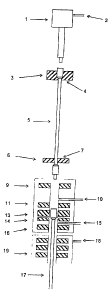
Referring to Figs. 1, 2 and 3 a top drive (1) has a flushing inlet (2) and is
adapted to connect to a tubular (S). Grips (4) can grip tubular (5) and form
part
of top handler (3), there is a bottom handler (6) and guide (7). The coupler
comprises upper annular preventer (9), flushing outlet (10). There is a blind
preventer (11) which can separate the upper and lower sections of coupler.
There are upper grips (12) and lower grips (13) which are capable of gripping
the tubular. There are slips (14) and flushing inlet (15) and the lower
annular
preventer (16). The lower grips (13) can grip the top of the drill string
(17). In
the embodiment of fig. 3 there is a rotating BOP (19) and rotating slips and
grips
(8) as shown.
In use the sequence shown in figs. 4, S, and 6 is followed in order to add a
tubular to a drill string and the sequence of operations is shown in more
detail in
Table 1. In the Table the handlers refer to the means to move a tubular into
position.
Referring to Fig. 7, the handler is shown generally at (20), mounted on
vertical
supports (21), which can be moved horizontally, so that the handler can be
moved up and down and also towards and away from the centre line of the drill
string. The handler separates into two parts (22a) and (22b), in order to
approach
and enclose the connection between tubulars (24) and (25). The clamping
section of the handler contains a lower annular preventer (26), slips (27),
lower
wrench (28), upper wrench (29), blind preventer.(30) and upper preventer (31).
Mud and other fluids can flow in through pipe (32) arid out through pipe (33).
The umbilieals for power, monitoring and control pass through flexible
conduits
at (34) (35).
In use, the handler can be positioned around the connection between tubulars
(24) and (25) as they are rotating and rising upwards. The series of events
are as
follows:-
(i) The handler moves upwards at the same speed as the drill string and the
two
parts (22a) and (22b) come together enclosing the connection between tubulars
(24) and (25).
CA 02550981 1997-10-14
13
Table 1
Adding one pipe, or stand of pipes, to the drillstring
Activity Sequence for one cycle
Figs. 4, 5 and 6
'Top Drive' Connector 'Handlers'
Activities
1 Lower drillstring to
bottom stop
2 Start rotation & Close slips
3 Lower 'upset' onto
slips
4 Close grips and seals
S Rotate passively Rotate actively
6 (Flush if mud being used)
7 Start circulation
8 Rise passively Break & back off joint
9 Hold position Release upper grip
10Raise to clear blind
preventer
1 Stop circulation Close blind preventer
I
12(Flush if mud being
used)
13 Open upper annular preventcr
14Stop rotation & raise
to top stop
15 Swing in new pipe
16Lower & make up joint
17 Top releases grip
18 Top s<vings away
19Lower pipe to blind
preventer
20Start Rotation Bottom swings away
21 Close upper annular preventer
22(Flush if mud being
used)
23Start circulation
24 Open blind preventer
25Lower pipe through
upper grip
26. Close upper grip
27Rotate passively Rotate actively
28Lower passively Make up joint
29 Stop circulation
30~ (Flush if mud being used)
31Rotate actively Rotate passively
32 Open both grips & both annular
preveaters
33Raise drillstring off
slips
34 Open slips & stop rotation
I Lower drillstring to
bottom stop
and repeat cycle
Removing one pipe, or stand of pipes, from the drillstring
achieved by running the above sequence in reverse
CA 02550981 1997-10-14
14
(ii) The handler is then moved up faster until the rotating slips (2?) take
the
weight of the drill string.
(iii) The annular preventers (26) and (21) close, the rotating wrenches (28)
and
(29) grip the connection upsets and the circulation fluid flushes in through
(32)
and temporarily out of (33).
(iv) The upper wrench (29) turns faster, or slower, than the lower wrench
(28),
thereby backing off tubular (24) from tubular (25) and circulation fluid from
(32) now enters the drillstring.
(v) The upper wrench (29) ungrips and allows the tubular (24) to be raised up
until the blind preventer (30) cam close beneath it.
(vi) The contents of tubular (24) are flushed out via (36) from the other
handler
above.
(vii) Tubular (24) is raised clear of this handler, which continues to rise
up,
rotate and circulate tubular (25).
(viii) At the appropriate time, this handler ceases to take the weight of the
drill
string or provide rotation but continues to support tubular (25) and circulate
the
drill string.
(ix) This handler then raises tubular (25) a discreet distance, relative to
the other
handler below, before using (32) to flush out circulation fluid from tubular
(25)
with a fixed quantity of air, water or other fluid.
(x) This handler then raises tubular (25) clear of the lower handler and
transfers
tubular (25) to storage, where it disengages by separating the two sections
(22a)
and (22b).
(xi) This handler is then lowered to below the other handler and positioned
around the next connection as it comes clear of the wellhead or BOP stack and
the cycle is repeated as in (i) to (xi) above.
CA 02550981 1997-10-14
15
In use the sequence set out in fig. 4 is followed to add a tubular to a dril:
string
and is described in the Table. The handlers refer to the means to move a
tubular
into position.
The method of the invention enables a steady controllable fluid pressure
maintained on the exposed formation wall at all times from first drilling to
the
cementing of installed casing. This enables it to be much easier to hold the
hole
open and allows for a much easier choice of lighter muds which can greatly
reduce drilling costs. Previously mud circulation had to be stopped each time
a
jointed drill string joint is made or broken and this prevented continuous mud
circulation and inevitably meant that there were significant surges in
downhole
pressure. In addition mud weights were calculated on the basis of providing a
specific static head pressure which is no longer required in the method of the
invention.