Note: Descriptions are shown in the official language in which they were submitted.
CA 02551093 2011-07-13
POT AND PAN WASHING MACHINE, COMPONENTS,
AND METHODS OF WASHING ITEMS
Field of the Invention
The present invention relates to improvements in a pot and pan washing
machine.
More specifically the present invention relates to improvements within the
wash tank portion
of a pot and pan washing machine, including an improved intake manifold and, a
divider for
isolating a portion of the wash tank, and methods for washing pots, pans,
utensils and other
similar items.
Background of the Invention
Pot and pan washing machines, of the type used in restaurants, institutions
and other
eating facilities often involve a large wash tank or basin in which water is
circulated about
the pots and pans to provide a washing action. One such machine is described
in U.S. Patent
No. 4,773,436 issued to Cantrell et al. The machine of Cantrell includes a
wash tank with
multiple jets evenly spaced apart at an elevated position along the rear wall
of the wash tank.
The tank is filled with water to a level above the position of the jets. Pots
and pans are placed
in the wash tank, and a pump is activated to draw water from within the wash
tank and direct
it through the jets to create a jet stream. Each jet directs its jet stream
toward the bottom wall
of the wash tank, the bottom wall then deflects the jet stream upward and
towards the front
wall of the tank. The front wall then deflects the upward moving jet stream
towards the rear
wall of the tank, and the rear wall deflects the jet stream downward and back
towards the
front wall along the bottom wall. The combination of
1
CA 02551093 2006-06-21
WO 2005/062939
PCT/US2004/043368
deflections of the jet stream from the bottom, front and rear walls provides a
rolling washing
action within the wash tank.
The basic components of the wash tank of the pot and pan washing machine of
the prior
art are shown in Fig. 1. Wash tank 10 includes end walls 12 and 14, rear side
wal116, front side
wall 18 and bottom wall 19. A pump can be attached to either end wall; in the
embodiment
shown in Fig. 1, pump 50 is attached to right end wall 14. An impeller located
within pump 50 is
driven by electric motor 56. The impeller draws fluid into pump inlet 52
through an intake port
(not shown) located in end wall 14. The fluid is then discharged from the pump
through pump
outlet 54 and into outlet manifold 60. Outlet manifold 60 includes a ninety
degree turn, and
several other turns, to direct the fluid across the back side of rear wall 16
and out jet nozzles 20
which are protruding through and extending from rear wall 16. The intake port
associated with
pump inlet 52 is covered by perforated intake manifold 30. Intake manifold 30
includes handle
36 and is removably supported within wash tank 10 for easy cleaning. Intake
manifold 30 fits
tightly between outer runner 32 and inner runner 34, each of which extends
vertically from
bottom wall 19. Heating element 40 is positioned between intake manifold 30
and end wall 14
for its protection and to maximize the use of space.
Although the prior art pot and pan washing machine disclosed in U.S. Patent
No.
4,773,436 provides an exceptional wash action, many of the components
discussed above hinder
the overall efficiency and perfonnance of the machine. The inventions
disclosed in copending
U.S. Application Serial No. 09/947,484 provide components that greatly
increase the overall
efficiency and performance of the machine, including an improved intake
manifold positioned
along the rear wall of the machine as shown in Fig. 2. The invention disclosed
in U.S.
Application Serial No. 09/947,484 provides a scaleable, self-cleaning intake
manifold that has a
generally linear intake path. Nevertheless, the improved intake manifold
itself has several
disadvantages that result in a reduction of efficiency and performance.
The main problem with the prior art pump intakes in a pot washing system is
that a fluid
will take the path of least resistance to the inlet of the pump. Therefore,
the volume of fluid
nearest the pump intake will be pulled in at a much greater rate than the
volume farthest away
2
CA 02551093 2006-06-21
WO 2005/062939
PCT/US2004/043368
from the intake. This "sucking" action creates problems in pot and pan washing
systems as it
will eventually draw the wares toward the intake-end of the wash sink (a
phenomenon called
"pan migration") where they can potentially "pile up", blocking the inlet
manifold and starving
the pump by restricting the fluid flow to the inlet. This occurs on all
existing pot and pan
washing systems, including systems utilizing linear intake manifold 130 shown
in Fig. 2, which
includes holes evenly spaced across the entire surface of the intake manifold.
In the case of
intake manifold 130 the even spacing of holes result in over 90% of the fluid
transfer from the
sink to pump 150 takes place in the first 50% of the intake, creating a large
vacuum due to the
suction of the water through holes in the intake. In addition, the fluid
entering pump 150 is fairly
turbulent as the path of most of the fluid must turn a sharp angle (generally
ninety degrees)
almost immediately from the point in which the fluid enters intake manifold
130 to the point in
which the fluid enters pump 150. This too reducing the efficiency and
performance of pump
150.
In order to provide the most efficient wash action within the entire volume of
the wash
sink it is desirable to develop a pump intake manifold that will introduce
fluid to the pump inlet
in such a way as to minimize the vacuum effect of the pump (as it draws in the
fluid) and to
minimize the turbulence of the fluid prior to reaching the pump inlet.
Although a machine that employs a wash tank and jet stream of the type
described above
is extremely useful for washing pots and pans, it is less desirable for
washing smaller items such
as utensils. In addition, it is difficult to separate items that require
different levels of cleansing
within the single wash tank of the above-described washing machine. In an
attempt to provide a
segregated wash area for items such as utensils, utensil baskets are often
located within the wash
tank. The invention disclosed in U.S. Application No. 09/947,485 provides a
powered utensil
basket that captures a jet stream from the washing machine in which the basket
is located to
maintain the washing action of the machine within the basket. Although the
powered utensil
basket does provide a segregated washing area for utensils and other items
that is removable
from the washing machine, the basket itself is rather bulky and often not
utilized in operation.
Therefore, it is desirable to provide a segregated washing area within a wash
tank that does not
3
CA 02551093 2006-06-21
WO 2005/062939
PCT/US2004/043368
require the placement of a bulky utensil basket in the wash tank, while at the
same time
maintaining the wash action of the machine.
Summary of the Invention
A principal object of the present invention is to provide a cost efficient pot
and pan
washing machine having exceptional efficiency and performance characteristics.
Another object
of the present invention is to increase the efficiency and performance of the
pot and pan washing
machine through the use of an inventive intake manifold that minimizes the
pressure differential
between the interior (non wash take side) of the intake manifold and the
exterior (wash tank side)
of the manifold, and that minimizes turbulence in the fluid path. Another
object of the instant
invention is to utilize the "dead" space in the back (along the rear wall) of
the wash sink where
minimal "wash action" takes place. Yet another object of the instant invention
is to provide an
intake manifold that has the least amount of pressure differential at the
intake wall in order to
minimize the possibility of items being pulled down to the manifold and being
held in place due
to the vacuum created by the difference in pressure.
Yet another object of the instant invention is to provide a segregated washing
area within
a wash tank that maintains the wash action of the machine.
According to the above described objects of the instant invention, a pot and
pan washing
machine is provided including an improved intake manifold and a partition (or
divider). The
intake manifold of the instant invention is positioned along the length of the
rear wall of the
washing machine. This position provides several unique advantages, which are
discussed in U.S.
Application No. 09/947,484. In addition, the surface of the intake manifold of
the instant
invention includes a hole (or void) pattern that facilitates uniform suction
along the entire length
of the manifold.
The hole pattern of the instant is accomplished by gradually introducing holes
in the
intake and increasing the number of holes as the distance from the pump
increases in order to
spread the potential for vacuum across the length of the intake. In the
preferred embodiment a
"long" or "large" intake surface is utilized as utilizing a smaller surface
area would make it more
4
CA 02551093 2006-06-21
WO 2005/062939
PCT/US2004/043368
difficult to create enough openings, using the appropriate pattern(s), to
allow for a balanced
suction throughout the length of the intake.
In the preferred embodiment of the instant invention, number of holes (i.e.
the void
concentration) increases as the distance from the pump inlet increases. This
results in a more
uniform, and minimal, vacuum across the entire length of the intake which
eliminates the
potential for items, such as small lids, small trays, dish towels, etc., to be
sucked down and held
against the surface of the intake. As there will always be some difference in
pressure at the voids
there will never be a true "zero vacuum"; however the pattern of the instant
invention comes very
close.
Another important benefit of the varying hole concentration of the instant
invention is
that the pattern helps to create a linear "chute" for the water to travel
through prior to entering the
pump. This helps align the water to create a more laminar flow into the pump,
thus creating less
turbulence, which results in more efficient pump operation.
In a preferred embodiment of the instant invention, a minimum void
concentration is
provided near the suction source (the intake manifold inlet). This minimum
void concentration is
provided to eliminate swirling (whirlpool or eddy) that is created when the
jets of the washing
machine introduce fluid to an area in which no fluid is removed.
An additional feature of a preferred embodiment of the instant invention is
the inclusion
of a maximum void concentration within a predetermined area. The purpose of
the maximum
void concentration is to prevent items, such as dish towels, from sticking to
the intake manifold
during operation. The maximum void concentration for an area is based upon the
amount of
suction that is desired across that area. Thus, as the suction from the pump
decreases as the
distance from the intake inlet increases, the maximum void concentration will
increase for a
given surface area. In addition to the maximum void concentration, the voids
of the intake
manifold of a preferred embodiment have a maximum area to prevent small items
and debris
from being drawn into the intake manifold.
The divider of the instant invention provides a segregated washing area within
the wash
tank of the pot and pan washing machine, in which the washing action of the
machine is
CA 02551093 2006-06-21
WO 2005/062939
PCT/US2004/043368
maintained. The divider is removable and repositionable via a series of
channels located along
the walls of the wash tank.
The foregoing and other objects are intended to be illustrative of the
invention and are not
meant in a limiting sense. Many possible embodiments of the invention may be
made and will
be readily evident upon a study of the following specification and
accompanying drawings
comprising a part thereof. Various features and subcombinations of invention
may be employed
without reference to other features and subcombinations. Other objects and
advantages of this
invention will become apparent from the following description taken in
connection with the
accompanying drawings, wherein is set forth by way of illustration and
example, an embodiment
of this invention.
6
CA 02551093 2006-06-21
WO 2005/062939
PCT/US2004/043368
Description of the Drawings
Preferred embodiments of the invention, illustrative of the best modes in
which the
applicant has contemplated applying the principles, are set forth in the
following description and
are shown in the drawings and are particularly and distinctly pointed out and
set forth in the
appended claims.
Figure 1 is a perspective view from above of a prior art pot and pan washing
machine
with a portion of the front and one side wall of the wash tank cut away to
better illustrate certain
interior construction details.
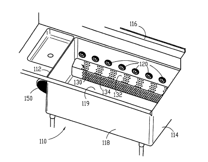
Figure 2 is a fragmentary perspective view from above of another pot and pan
washing
machine showing a generally linear intake manifold including evenly spaced
perforations along
the length of the intake surface.
Figure 3 is a fragmentary perspective view from above of the pot and pan
washing
machine of Fig. 2 utilizing the intake manifold of the instant invention.
Figure 4 is a perspective view from above of a pot and pan washing machine
including
the partition of the instant invention with a portion of the front and one
side wall of the wash tank
cut away to better illustrate certain interior construction details.
Figure 5 shows the hole pattern of the inventive intake manifold shown in Fig.
3.
7
CA 02551093 2006-06-21
WO 2005/062939
PCT/US2004/043368
Description of a Preferred Embodiment
Referring to the drawing figures, therein is shown an optimum form of the
subject pot and
pan washing machine with essentially all features usable to increase
performance, versatility and
efficiency therewithin. Preferred embodiments of the present invention are
hereinafter described
with reference to the accompanying drawings.
The operation of the pot and pan washing machine described hereinafter is
substantially
similar to the operation of the prior art machine described above. The instant
invention provides
significant features that increase the performance, versatility and efficiency
of the pot and pan
washing machine.
Referring to Fig. 3, a preferred embodiment of the wash tank of the inventive
pot and pan
washing machine is shown. The wash tank/basin of the instant invention is
constructed in
essentially the same manner as the wash tanks of the prior art. Wash tank 110
includes left end
wall 112, right end wall 114, rear side wall 116, front side wall 118 and
bottom wall 119
constructed in the same or similar manner, and of the same or similar
materials as the wash tank
of the prior art. Figure 3 shows the components of the pot and pan washing
machine as they are
located in association with wash tank 110. Pump 150 is attached to left end
wall 112 in the
embodiment shown in Fig. 3. As has been discussed with respect to the prior
art, pump 150 can
be attached to either left end wall 112 or right end wall 114 of wash tank
110. In addition it is
= understood that pump 150 could be attached to any other wall of the wash
tank, or otherwise
located separate from the wash tank and connected to the interior of the wash
tank via a hose or
other piping. Flush mounted jet nozzles 120 are mounted along rear wall 116
equally spaced
apart from one another. Intake manifold 130 is mounted within wash tank 110
along the bottom
portion of rear wall 116, below nozzles 120.
Intake manifold 130 is shown installed within wash tank 110 in Fig. 3. Intake
manifold
130 includes an upper portion 132 extending outwardly from rear wall 116
toward front wall
118, and lower portion 134 extending from the front end of upper portion 132.
In a preferred
embodiment, the upper portion of intake manifold 130 is angled downward from
rear wall 116.
The downward angle of the upper portion of intake manifold 130 corresponds to
the downward
8
CA 02551093 2006-06-21
WO 2005/062939
PCT/US2004/043368
angle of jet nozzle 120 which directs a fluid path toward the front portion of
bottom wall 119 as
described above with respect to the prior art washing machine.
Portions of the intake manifold are perforated to allow fluid to be drawn into
manifold
130 by the pump. The amount of perforations can vary depending upon the amount
of
vacuum desired and the flow rate of the pump. The void concentration, i.e. the
number of
perforations or the total area of void versus the total surface area for a
given section of the
intake manifold, increases as the distance from the point of suction
increases. In the case of
the embodiment shown in Fig. 2, the point of suction is pump 150 or the intake
inlet of the
intake manifold which extends through end wall 112 and is connected to the
pump.
Increasing the number and size of the perforations will result in a decreased
vacuum and
increased efficiency. In a preferred embodiment, a maximum void size for each
individual
perforation is utilized to prevent debris and small items from entering the
intake manifold.
Perforations can be located only on upper portion 132, only on lower portion
134, or on both
upper portion 132 and lower portion 134; in the preferred embodiment however
it is desirable
to include perforations an both upper portion 132 and lower portion 134 so as
to maximize
the surface area over which perforations can be located and thus decreasing
the pressure
differential for any given perforation.
In the preferred embodiment shown in Fig. 3, a minimum void concentration is
provided
near pump 150 to prevent a swirling, whirlpool, or eddy effect that would be
caused by the jet
nearest the pump introducing fluid into the region of the wash tank without
any fluid being
removed. An additional feature of a preferred embodiment of the instant
invention shown in Fig.
3 is the inclusion of a maximum void concentration within a predetermined
area. The purpose of
the maximum void concentration is to prevent items, such as dish towels, from
sticking to the
intake manifold during operation. The maximum void concentration for an area
is based upon
the amount of suction that is desired across that area. Thus, as the suction
from pump 150
decreases as the distance from the intake inlet increases, the maximum void
concentration will
increase for a given surface area. In addition to the maximum void
concentration, the voids of
9
CA 02551093 2006-06-21
WO 2005/062939
PCT/US2004/043368
the intake manifold of a preferred embodiment have a maximum area to prevent
small items and
debris from being drawn into the intake manifold.
In will be appreciated that intake manifold 130 obtains an enclosed interior
within
manifold portions 132 and 134, rear side wall 116, end walls 112 and 114, and
bottom wall
119. Thus, the walls of the pot and pan washing machine also act as walls for
the intake
manifold, and the inlet (not shown) that extends through end wall 112 from
pump 150 is the
inlet to intake manifold 130. Nevertheless, it is understood that in
alternative embodiments
of the instant invention, the inlet to the intake manifold can be located in
any of the walls of
the washing machine, or even be separate from the walls of the machine.
The jet nozzles of the embodiment shown in Fig. 3 are flush mounted to rear
wall 116
of the wash tank. An annular outer ring is mounted to rear wall 116 on the
inner side of the
wash tank. A directing tube extends from an inner circumference of the outer
ring, through a
hole in rear wall 116 and into an outlet manifold. The directing tube diverts
the fluid path
moving through the outlet manifold into a jet stream. The directing tube has a
predetermined
angle to direct the jet stream toward the front portion of bottom wall 119.
In a preferred embodiment of the instant invention, upper portion 132 of the
intake
manifold is positioned within the fluid path of nozzle 120. The jet stream
from flush
mounted nozzle 120 impacts the intake manifold at a position generally near
rear wall 116
and skims across the surface of the upper portion of intake manifold 130.
Intake manifold
130 is thereby self-cleaning in that jet nozzle 120 blows any debris away from
the
perforations of the intake manifold. The preferred embodiment of the intake
manifold shown
in Fig. 3 includes the upper and lower portions that are connected to rear
wall 116 and bottom
wall 119, respectively to form an inclosure within the intake manifold.
Additional walls can
be utilized if it is not desired to have the intake manifold connected to both
the rear and
bottom walls. In addition, the intake manifold can be located substantially at
the exterior of
the wash tank, thus including an intake surface that extends into the interior
of the wash tank.
The intake manifold can be made removable in a manner similar to that of the
prior art;
however, since the preferred embodiment is self-cleaning (described above),
the inventive
CA 02551093 2006-06-21
WO 2005/062939
PCT/US2004/043368
intake manifold can be permanently connected within the wash tank using any
means known
in the art. A heater can be positioned within the intake inclosure for safety
and protection.
In operation, wash tank 110 is filled full of water, soap and pots and pans to
a level above
jet nozzles 120. The soapy water, or fluid is drawn through the perforations
(voids or holes) in
intake manifold 130 by pump 150. The fluid enters pump 150 through an intake
inlet in a first
direction that is generally parallel to rear wall 116. The fluid is discharged
from the pump
through an outlet into an outlet manifold. Jet nozzle 120 diverts the fluid
from the outlet
manifold into a jet stream directed toward the front portion of bottom wall
119. The jet stream
skims across the upper portion of intake manifold 130 as it travels from the
jet nozzle to the
bottom wall of the wash tank. The jet stream is deflected from bottom wall
into a wash action in
a Manner substantially similar to that of the prior art.
Divider 210 of the instant invention (Fig. 4) provides a segregated washing
area within
the wash tank of the pot and pan washing machine, in which the washing action
of the machine is
maintained. The divider is removable and repositionable via a pair of directly
opposing channels
220 extending upward from bottom wall 19 along front wal118 and rear wall 16.
Channels 220
can be included between any of jets 20. In addition multiple pairs of channels
220 can be
provided within the wash tank to allow a single wash tank to be easily
customizable by allowing
for numerous variations of partitioning, either by repositioning a single
divider 210 into different
channels 220 (resulting in two segregated areas within the wash tank), or by
positioning multiple
dividers 210 into multiple channel pairs 220 (resulting in three or more
segregated areas within
the wash tank). It will be appreciated that channels 220 can be welded or
otherwise attached to
the interior of walls 16 and 18 such that the channels protrude from said
walls, or the channels
can be grooves extending into walls 16 and 18. Divider 210 is inserted into
channels 220 from
above the wash tank.
Divider 210 shown in Fig. 4 includes perforations to allow fluid to flow
through the
divider to intake 30. It will be appreciated that divider 210 can be a solid
wall when intake
manifold 130 of the instant invention is utilized. This is because intake
manifold 130 extends
11
CA 02551093 2006-06-21
WO 2005/062939
PCT/US2004/043368
along the entire length of rear wall 116 with perforations on each side of
divider 210, and thus,
fluid can be pulled into intake manifold 130 from either side of divider 210.
In operation, when divider 210 is inserted into channels 220, the washing
action
created by jets 20 will not be affected, and the wash action of the washing
machine will be
substantially maintained within the segregated areas created by divider 210.
The pot and pan washing machine of the instant invention and its components
are all
preferably constructed of stainless steel to increase the life of the machine;
however, any
other suitable material known in the art may also be utilized.
In the foregoing description, certain terms have been used for brevity,
clearness and
understanding; but no unnecessary limitations are to be implied therefrom
beyond the
requirements of the prior art, because such terms are used for descriptive
purposes and are
intended to be broadly construed. Moreover, the description and illustration
of the inventions
is by way of example, and the scope of the inventions is not limited to the
exact details shown
or described.
Certain changes may be made in embodying the above invention, and in the
construction thereof, without departing from the spirit and scope of the
invention. It is
intended that all matter contained in the above description and shown in the
accompanying
drawings shall be interpreted as illustrative and not meant in a limiting
sense.
Having now described the features, discoveries and principles of the
invention, the
manner in which the inventive pot and pan washing machine is constructed and
used, the
characteristics of the construction, and advantageous, new and useful results
obtained; the
new and useful structures, devices, elements, arrangements, parts and
combinations, are set
forth in the appended claims.
It is also to be understood that the following claims are intended to cover
all of the
generic and specific features of the invention herein described, and all
statements of the scope
of the invention which, as a matter of language, might be said to fall
therebetween.
12