Note: Descriptions are shown in the official language in which they were submitted.
CA 02551127 2006-06-15
WO 2005/061033 PCT/US2004/039233
TREATMENT OF BREAKTHROUGH PAIN BY DRUG AEROSOL INHALATION
BACKGROUND
Reference to Related Applications
(0001] This application claims priority to U.S. Provisional application Ser.
No.
601530,058 entitled "Treatment of Breakthrough Pain by Drug Aerosol
Inhalation," filed
December 16, 2003, Rabinowitz, Shen and Wensley, the entire disclosure of
which is hereby
incorporated by reference.
Field
[0002] Embodiments generally relate to devices comprising a first compound and
a
second compound wherein the second compound can counteract the pharmacological
effects
of the first compound, and in particular, to devices fox producing an aerosol
of a first
compound, to methods of producing an aerosol of a first compound using such
devices, and
to methods of using such devices and methods.
Introduction
[0003] Many potentially abusable drugs play an important role in current
medical
practice. Such abusable drugs include, for example, opioid analgesics, psycho-
stimulants,
cannabinoid agonists, dopamine agonists, steroids, and sedative hypnotics. For
many
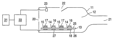
abusable drugs, rapid, non-invasive delivery can have important medical
advantages,
including convenient fast onset of therapeutic effect, facilitation of patient
titration to the
minimum effective drug dose, dose reproducibility, and high bioavailability.
Intrapulmonary
administration of an aerosol comprising a potentially abusable drug is one
means of effecting
rapid drug delivery that can enable realization of the above benefits.
[0004] In administering an abusable drug to a patient, it can be advantageous
to
provide the drug in a form that mitigates the potential for misuse of the
drug, either by the
CA 02551127 2006-06-15
WO 2005/061033 PCT/US2004/039233
patient or by a drug abuser. Such misuse can take the form of excessive dosing
of the drug
by the intended route of administration, for example, by administering
multiple doses instead
of a single dose or by inhaling a nebulized drug solution for longer than the
prescribed
duration. Additionally, misuse can involve changing the route of
administration of the drug,
for example, by crushing a time-release capsule and then nasally ingesting the
drug, or by
intravenous injection of a drug solution intended for nebulization.
[0005] Electronic lockout means for preventing excessive use of an aerosol
form of
an abusable substance such as an opioid by its intended route of
administration have been
proposed. An example of the use of an electronic lockout feature to prevent an
aerosol
generating apparatus from producing aerosols more frequently than a prescribed
time interval
is disclosed in U.S. Patent 5,694,919. While an electronic lockout feature can
prevent
overdosing, such an electronic lockout feature is ineffective at preventing
misuse of the drug
by changing the route of administration.
[0006] Providing abusable substances in a tamper-proof physical enclosure
represents
one method of preventing abuse by changing the route of administration.
However,
sequestering an abusable substance in a physical enclosure to prevent access
by an abuser, as
proposed in U.S. Patent 5,694,919, can be difficult to implement in a manner
that is both
commercially viable and effective in protecting an abusable drug from misuse.
[0007] There is a need for improved devices and methods of preventing a drug
formulation, and in particular a drug formulation comprising an abusable
substance intended
for aerosol delivery, from being extracted from the delivery apparatus for
subsequent abuse.
Summary
2
CA 02551127 2006-06-15
WO 2005/061033 PCT/US2004/039233
[0008] A device is provided comprising a housing defining an airway, at least
one
support configured to couple to the airway comprising at least one area
selected from a first
area and a second area, wherein a first compound is disposed on the first
area, and a second
compound is disposed on the second area, and wherein the second compound can
counteract
the pharmacological effects of the first compound, and a mechanism configured
to release the
first compound into the airway, wherein the device comprises at least one
first area and at
least one second area. The potential for abuse of the first compound can be
prevented or
minimized by having the first compound and a second compound, which can
counteract the
pharmacological effects of the first compound, within the same device such
that the first and
second compounds are indistinguishable.
[0009] A method is provided for producing an aerosol of a first compound
comprising providing at least one first area on which is disposed a first
compound, and at
least one second area on which is disposed a second compound, wherein the
second
~ compound can counteract the pharmacological effects of the first compound,
providing an
airflow over at least a portion of the at least one first area, and releasing
the first compound
from at least a portion of the at least one first area into the airflow,
wherein the first
compound forms an aerosol in the airflow.
[0010] It is to be understood that both the foregoing general description and
the
following detailed description are exemplary and explanatory only and are not
restrictive of
certain embodiments, as claimed.
Description of the Drawings
3
CA 02551127 2006-06-15
WO 2005/061033 PCT/US2004/039233
[0011] The accompanying figures, which are incorporated in and constitute a
part of
this specification, illustrate several embodiments and together with the
description serve to
explain certain embodiments.
[0012] FIG. 1 is a schematic illustration of a device consistent with certain
embodiments.
[0013] FIG. 2 is a schematic illustration of a device consistent with certain
embodiments.
[0014] FIG. 3 is a schematic illustration of a device consistent with certain
embodiments.
[0015] FIG. 4 is a schematic illustration of a device consistent with certain
embodiments.
[0016] FIG. SA is a schematic illustration of a support consistent with
certain
embodiments.
[0017] FIG. SB is a schematic illustration of a support consistent with
certain
embodiments.
[0018] FIG. 6A is a schematic illustration of a support consistent with
certain
embodiments.
[0019] FIG. 6B is a schematic illustration of a support consistent with
certain
embodiments.
[0020] FIG. 7A is a schematic illustration of a support comprising first and
second
areas consistent with certain embodiments.
[0021] FIG. 7B is a schematic illustration of a support comprising first and
second
areas consistent with certain embodiments.
4
CA 02551127 2006-06-15
WO 2005/061033 PCT/US2004/039233
[0022] FIG. 7C is a schematic illustration of a support comprising first and
second
areas consistent with certain embodiments.
[0023] FIG. 8 is a schematic illustration of a support consistent with certain
embodiments.
[0024] FIG. 9 is a schematic illustration of control circuitry consistent with
certain
embodiments.
[0025] Unless otherwise indicated, all numbers expressing quantities of
ingredients,
reaction conditions, and so forth used in the specification and claims are to
be understood as
being modified in all instances by the term "about."
[0026] In this application, the use of the singular includes the plural unless
specifically stated otherwise. In this application, the use of "or'i means
"and/or" unless stated
otherwise. Furthermore, the use of the term "including," as well as other
forms, such as
"includes" and "included," is not limiting. Also, terms such as "element" or
"component"
encompass both elements and components comprising one unit and elements and
components that comprise more than one subunit unless specifically stated
otherwise.
[0027] The section headings used herein are for organizational purposes only,
and are
not to be construed as limiting the subject matter described. All documents
cited in this
application, including, but not limited to patents, patent applications,
articles, books, and
treatises, are expressly incorporated by reference in their entirety for any
purpose.
Description of Various Embodiments
CA 02551127 2006-06-15
WO 2005/061033 PCT/US2004/039233
[0028] Reference will now be made in detail to certain embodiments, examples
of
which are illustrated in the accompanying figures. Wherever possible, the same
reference
numbers will be used throughout the drawings to refer to the same or like
parts.
[0029] In certain embodiments, a device comprises a housing defining an
airway, at
least one support configured to couple to the airway comprising at least one
area selected
from a first area and a second area, wherein a first compound is disposed on
the first area,
and a second compound is disposed on the second area, and wherein the second
compound
can counteract the pharmacological effects of the first compound, and a
mechanism
configured to release the first compound into the airway, wherein the device
comprises at
least one first area and at least one second area.
[0030] Certain embodiments of a device are schematically illustrated in FIG.
1.
FIG. 1 shows embodiments of a portable inhalation device for the
intrapulmonary delivery of
an aerosol to a patient. The device shown in FIG. 1 can provide for multiple
doses of a first
compound, and each dose can be delivered to a patient in a single inspiration.
[0031] In certain embodiments, devices illustrated in FIG. 1 can comprise a
housing
11 defining an airway 12. Airway 12 can include an inlet 20 and an outlet 21
to provide an
airflow through airway 12, for example, upon inhalation through the mouth
and/or the
nostrils by a patient at outlet 21. In certain embodiments, the airflow rate
and airflow
velocity within airway 12 can be controlled by an airflow control valve 22
incorporated into
the wall of housing 11. In certain embodiments, airflow control valve 22 can
be a gate that
allows additional air to enter airway according to the pressure differential
between airway 12
and external to housing 11.
6
CA 02551127 2006-06-15
WO 2005/061033 PCT/US2004/039233
[0032] In certain embodiments, an actuation mechanism 23, capable of
transducing
the airflow velocity through airway 12 into an electrical or mechanical
signal, such as, for
example, a thermistor or pressure transducer, can be located in airway 12. In
certain
embodiments, actuation mechanism 23 can be electrically connected to a
controller 33.
Controller 33 can be further electrically connected to a power source 31 and
to a release
mechanism 18 comprising, for example, resistive heating elements. Controller
33 includes
circuitry (not shown) to connect power source 31 to release mechanism 18 for
controlling the
release mechanism.
[0033] In certain embodiments, devices illustrated in FIG. 1 can include a
support 13
disposed within airway 12. In certain embodiments, support 13 can comprise two
first areas
14 comprising a first compound 16, and two second areas 15 comprising a second
compound
17 disposed on a first surface 25 of support 13. In certain embodiments, first
compound 16
and second compound 17 can be deposited as thin films on first areas 14 and
second areas 15,
respectively. In certain embodiments, release mechanism 18 can comprise
resistive heating
elements that can be located on or within a second surface 26 of support 13,
opposing first
areas 14 and second areas 15.
[0034] In certain embodiments, wherein electrical current provided by power
source
31 is applied to resistive heating element 18, heat is generated. Heat
generated by heating
element 18 can be conducted through support 13, which, in certain embodiments,
can
comprise a thermally conductive material such as, for example, stainless
steel, to heat at least
one first area 14 and first compound 16 disposed thereon. When heated to a
sufficient
temperature, first compound 16 can thermally vaporize into airway 12, to form
an aerosol
comprising first compound 16 in the airflow within airway 12.
7
CA 02551127 2006-06-15
WO 2005/061033 PCT/US2004/039233
[0035] In certain embodiments, the operation of a device for intrapulmonary
delivery
of multiple doses of a first compound 16 according to FIG.1 can be described
as follows. A
patient can inhale on outlet 21 of a device to generate an airflow through
airway 12.
Actuation mechanism 23, upon detecting a certain airflow velocity, can send a
signal to
controller 33. Upon receipt of the signal from actuation mechanism 23,
controller 33 can
electrically connect power source 31 to one of the resistive heating elements
18 underlying
first area 14 comprising first compound 16. Heat generated by resistive
heating element 18
can be conducted through support 13 to heat first area 14 causing first
compound 16 to
thermally vaporize to form an aerosol comprising agonist compound 16 in airway
12. The
aerosol comprising first compound 16 can then be administered to the patient
during
inhalation, to deliver a dose of first compound 16 to the patient's
respiratory tract. In certain
embodiments, device activation and administration of a dose of first compound
16 can take
place during a single inhalation.
[0036] In certain embodiments, for delivery of a subsequent dose of first
compound
16, the same process can take place with the difference that controller 33 can
connect a
second resistive heating element 27 to power source 31. When activated by
actuation
mechanism 23 upon sensing a certain airflow velocity, second resistive heating
element 27
can cause first compound 16 disposed on a second first area 14 to thermally
vaporize and
form an aerosol in the airflow through the airway 12. In certain embodiments,
controller 33
can prevent the resistive heating elements from heating and releasing second
compound 17
disposed on second areas 15.
[0037] Tn certain embodiments, misuse of first compound 16 can be minimized or
prevented by locating second areas 15 comprising second compound 17 between
first areas
8
CA 02551127 2006-06-15
WO 2005/061033 PCT/US2004/039233
14 comprising first compound 16 and/or by having the first compound 16 and
second
compound 17 be visually indistinguishable.
[0038] In certain embodiments, devices can be adapted to conventional aerosol
delivery apparatus, such as, for example, metered-dose inhalers (MDIs), dry
powder inhalers
(DPIs), small volume nebulizers, large volume nebulizers, ultrasonic
nebulizers, nasal sprays
and the like. In certain embodiments, nebulizer inhalers can produce a stream
of high
velocity air that can cause a therapeutic agent to spray as a mist that can
then be carried into a
patient's respiratory tract. The therapeutic agent can be formulated in a
liquid form such as a
solution or a suspension of micronized particles typically exhibiting a
diameter of less than
p,m. In certain embodiments, DPIs can administer a therapeutic agent in the
form of a free
flowing powder that can be dispersed in a patient's air-stream during
inspiration. A dry
powder formulation can be loaded into a dry powder dispenser or into
inhalation cartridges or
capsules for use with a dry powder aerosol delivery device. In certain
embodiments, MDIs
can discharge a measured amount of a therapeutic agent using compressed
propellant gas.
Formulations for 1V>DI administration can include a solution or suspension of
an active
ingredient in a liquefied propellant. The formulations can be loaded into an
aerosol canister,
which can form a portion of an MDI device.
[0039] Certain embodiments of devices adapted to an MDI format are
schematically
illustrated in F1G. 2. FIG. 2 illustrates an inhalation device comprising
housing 11 that
defines airway 12. Airway 12 includes inlet 20 and outlet 21 such that an
airflow can be
generated in airway 12 when a patient inhales on outlet 21 of the device
either through the
mouth or the nostrils. In other embodiments, inlet 20 is omitted, and gas flow
is generated
solely by release of pressurized material. In certain embodiments, airway 12
is omitted and
9
CA 02551127 2006-06-15
WO 2005/061033 PCT/US2004/039233
aerosol is released directly from valve 42 into the environment. In certain
embodiments, the
device can comprise first area 14 comprising first compound 16, and second
area 15
comprising second compound 17. In certain embodiments, first area 14 can be
defined by
support 28 in the form of a cartridge or canister and second area 15 can be
defined by support
29 which also can be in the form of a cartridge or canister. First compound 16
and second
compound 17 can be retained within the respective cartridges or canisters in
the form of a
solution or suspension comprising a liquefied propellant such as
hydrofluoroalkane.
[0040] In certain embodiments, devices illustrated in FIG. 2 can be activated
by a
patient manually pushing cartridges 28 and 29 toward airway 12. When
translated a certain
distance toward airway 12, actuation mechanism 40 can open a release mechanism
comprising, for example, a valve 42 allowing a propellant within first area 14
to inject a dose
of liquid suspension comprising first compound 16 into airway 12 to form an
aerosol
comprising first compound 16 in the airflow. In certain embodiments,
subsequent doses of
first compound 16 can be released into airway 12 by repeated compression of
cartridges 28
and 29 to reopen valve 42.
[0041] Certain embodiments of devices are schematically illustrated in FIG. 3.
FIG.
3 illustrates certain embodiments in which support 13 can be in the form of a
disk, and the
release mechanism comprises optical heating. In certain embodiments, support
13 can
comprise first area 14 comprising a thin film of first compound 16 and second
area 15
comprising second compound 17. In certain embodiments, first area 14 and
second area 15
can comprise stripes located on first surface 25 near the perimeter of support
13. In certain
embodiments, first area 14 and second area 15 can comprise multiple first
areas 14 and
second areas 15 located on first surface 25 of support 13. In certain
embodiments, the
CA 02551127 2006-06-15
WO 2005/061033 PCT/US2004/039233
multiple first areas 14 and multiple second areas 15 can be interspersed. In
certain
embodiments, support 13 can be a thermally conductive material such as
stainless steel.
[0042) In certain embodiments of devices illustrated in FIG. 3, for a certain
rotational
position of support 13, a portion of first area 14 and second area 15 can be
coupled to airway
12 defined by housing 11. In certain embodiments, different portions of first
area 14 and
second area 15 can be coupled to airway 12 by rotating support disk 13 using a
rotation
mechanism 47. In certain embodiments, different first areas 14 and second
areas 15 can be
rotated into airway I2 by rotation mechanism 47. In certain embodiments,
rotation
mechanism 47 can comprise a manual andlor electronic advancement mechanism
[0043] In certain embodiments, the heating release mechanism can comprise an
optical source 42 to generate optical radiation 41 such as a Xenon flash lamp,
an optical
assembly that can include lenses 44 and reflectors 45 to direct and focus
optical radiation 41
onto area 46 located on second surface 26 of support 13 underlying at least a
portion of first
area I4 comprising first compound 16 coupled to airway 12.
[0044] As an example of the operation of a device according to FIG. 3, a
patient can
inhale at outlet 21 of housing 11 to create an airflow in airway 12. At a
certain airflow
velocity, actuation mechanism 23 can send a signal to controller 33.
Controller 33 can then
connect power source 31 to optical source 42, to generate optical radiation
41. Optical
radiation 41 can then be directed and focused onto area 46, causing local
heating of support
I3 underlying first area I4. Heat generated at area 46 of support 13 can then
be conducted to
a portion of first area 14, causing first compound 16 to thermally vaporize
into the airflow to
form an aerosol of first compound 16 in airway 12 which can then be inhaled by
a patient. In
71
CA 02551127 2006-06-15
WO 2005/061033 PCT/US2004/039233
certain embodiments, device activation and administration of first compound 16
can occur
during a single inhalation by a patient.
[0045] In certain embodiments, subsequent doses of first compound 16 can be
administered by advancing support 13 to couple a new portion of first area 14
and/or at least
one new first area 14 to airway 12 and to optical radiation 41.
[0046] In certain embodiments, devices can be schematically illustrated in
FIG. 4.
FIG. 4 illustrates support 13 in the form of a tape having first areas 14
comprising first
compound 16 and second areas 15 comprising second compound 17. In certain
embodiments, support 13'can comprise, fox example, a metal foil having
recesses to contain
first compound 16 and second compound 17. In certain embodiments, the recesses
can
facilitate retention of first compound 16 and second compound 17 such that
first compound
16 and second compound 17 can be in the form of a dry powder, liquid, andlor
thin film. In
certain embodiments, support 13 can further comprise a protective layer 75
located on first
surface 25 of support 13 on which first compound 16 and second compound 17 are
disposed.
In certain embodiments, protective layer 75 can comprise a polymer or metal
film that can
function to mechanically andlor environmentally protect the compounds, and, in
certain
embodiments, can be sealed to first surface 25 of support 13.
[0047] In certain embodiments, support 13 can be mechanically coupled to a
reel-to-
reel mechanism 72. In certain embodiments, advancing reel-to-reel mechanism 72
can move
support 13 to couple a portion of support 13 comprising first area 14 on which
is disposed
first compound 16 to airway 12 defined by housing 11 and to release mechanism
18.
[0048] As an example of the operation of certain embodiments of a device
illustrated
in FIG. 4, reel-to-reel assembly 72 can advance support 13 to couple first
area 14 comprising
12
CA 02551127 2006-06-15
WO 2005/061033 PCT/US2004/039233
first compound 16 to airway 12, and to release mechanism 18. In certain
embodiments,
release mechanism 18 can comprise, for example, an ultrasonic source, a
thermal source, or a
source of electromagnetic radiation. During advancement, protective layer 75
can be
removed from first surface 25 of support 13 to expose at least one dose of
first compound 16.
[0049) A patient can inhale on the outlet of airway 12 (not shown) to generate
an
airflow in airway 12. In certain embodiments of devices illustrated in FIG. 4,
when a certain
airflow velocity is measured by actuation mechanism 23, a signal can be sent
to controller
33. Controller 33 can electrically connect power source 31 to release
mechanism 18 to
release first compound 16 into airway 12 to form an aerosol comprising first
compound 16.
For example, in certain embodiments, release mechanism 18 can be an ultrasonic
source that
can produce an acoustic pulse that can eject first compound 16 from first area
14 into airway
12 to form an aerosol comprising first compound 16. In certain embodiments, an
aerosol
comprising first compound 16 can then be inhaled by a patient. In certain
embodiments,
following release of first compound 16 from first area 14, reel-to-reel
mechanism 72 can
advance support 13 to couple a second first area 14 to airway 12 and release
mechanism 18.
Upon actuation of release mechanism 18, a second dose of first compound 16 can
be released
into airway 12.
[0050) In certain embodiments, to prevent or minimize the potential for abuse
of first
compound 16, first areas 14 comprising first compound 16, and second areas 15
comprising
second compound 17 can be randomly interspersed along the length of support
13. In certain
embodiments, controller 33 can be programmed to advance reel-to-reel assembly
72 such
that only first areas 14 comprising first compound 16 can be coupled to airway
12 and to
release mechanism 18.
13
CA 02551127 2006-06-15
WO 2005/061033 PCT/US2004/039233
[0051] Certain embodiments of the invention are herein further described.
[0052] In certain embodiments, a housing can define the shape and dimensions
of an
airway, and can comprise at least one inlet, and at least one outlet. In
certain embodiments,
a housing can define more than one airway. In certain embodiments, a housing
can be any
appropriate shape or dimension for the intrapulmonary administration of an
aerosol. In
certain embodiments, a housing can have a shape and dimensions appropriate for
portable
use by a patient. "Patient" includes mammals and humans. In certain
embodiments, a
housing can be designed to accommodate andlor incorporate at least one
support, an
electronic controller, a release mechanism, an actuation sensor, a lock-out
mechanism, as
well as other components and/or features.
[0053] In certain embodiments, the dimensions of an airway can at least in
part be
determined by the volume of air that can be inhaled through the mouth or the
nostrils by a
patient in a single inhalation, the intended rate of airflow through the
airway, and/or the
intended airflow velocity at the surface of the support that is coupled to the
airway and on
which at least one first area is disposed. In certain embodiments, an airflow
can be generated
by a patient inhaling with the mouth on the outlet of the airway, and/or by
inhaling with the
nostrils on the outlet of the airway. In certain embodiments, an airflow can
be generated by
injecting air into the inlet such as for example, by mechanically compressing
a flexible
container filled with air and/or gas, or by releasing pressurized air and/or
gas into the inlet of
the airway. In certain embodiments, there is no airflow or airway and the
device releases the
aerosol into the environment directly, e.g., by passing a liquid under
pressure through a valve
or small holes.
14
CA 02551127 2006-06-15
WO 2005/061033 PCT/US2004/039233
[0054] In certain embodiments, a housing can be dimensioned to provide an
airflow
velocity through the airway sufficient to produce an aerosol of a first
compound following
release of the first compound from a first area into the airway. In certain
embodiments, the
airflow velocity can be at least 1 m/sec in the vicinity of the first area
from which the first
compound is released.
[0055] In certain embodiments, a housing can be dimensioned to provide a
certain
airflow rate through the airway. In certain embodiments, the airflow rate
through the airway
can range from 10 L/min to 120 L/min. In certain embodiments, the airflow rate
can range
from 10-60 L/min and, in other embodiments, from 10-40 Llmin. In certain
embodiments, an
airflow rate ranging from 10 L/min to 120 L/min can be produced during
inhalation by a
patient when the outlet exhibits a cross-sectional area ranging from 0.1 cm2
to 20 cm2. In
certain embodiments, the cross-sectional area of the outlet can range from 0.5
cm2 to 5 cm2,
and in certain embodiments, from 1 cm2 to 2 cm2.
(0056] In certain embodiments, an airway can comprise one or more airflow
control
valves to control the airflow rate and airflow velocity in airway. In certain
embodiments, an
airflow control valve can comprise, but is not limited to, at least one valve
such as an
umbrella valve, a reed valve, a ball valve, a flapping valve that bends in
response to a
pressure differential, and the like. In certain embodiments, an airflow
control valve can be
located at the outlet of the airway, at the inlet of the airway, within the
airway, and/or can be
incorporated into the walls of housing defining the airway. In certain
embodiments, an
airflow control valve can be activated electronically such that a signal
provided by a
transducer located within the airway can control the position of the valve, or
passively, such
as, for example, by a pressure differential between the airway and the
exterior of the device.
CA 02551127 2006-06-15
WO 2005/061033 PCT/US2004/039233
[0057] In certain embodiments, devices comprise at least one support,
comprising at
least one area selected from a first area and a second area. In certain
embodiments, the
support can retain a first compound, a second compound, or both a first
compound and a
second compound.
[0058] In certain embodiments, a support can comprise a release mechanism or
certain elements of a release mechanism.
[0059] In certain embodiments, a support can comprise any appropriate shape
and
dimensions. Certain shapes for the support include, but are not limited to,
rectangular inserts,
cylindrical inserts, containers, cartridges, disks, tapes, and the like. In
certain embodiments,
a support can be a separate element or can be a surface of another element.
For example, in
certain embodiments, the support can be an inner wall of the housing, or can
be the outer
wall of the release mechanism, such as the outer wall of a heat package. In
certain
embodiments, a support can be an enclosure such as a container wherein the
support defines
an inner volume.
[0060] Certain embodiments of supports are schematically illustrated in FIGS.
1, 2,
3, and 4.
[0061] Certain embodiments of a support are schematically illustrated in FIG.
1. As
shown in FIG. 1, support 13 can comprise a single structure in the form of a
rectangular
panel disposed within airway 12. In certain embodiments, support 13 can
comprise two first
areas 14 and two second areas 15 disposed on a first surface 25 of support 13,
all of which
are disposed within airway 12. First areas 14 and second areas 15 can be
positionally
distinguishable, meaning that the areas are discrete and do not overlap. In
certain
embodiments (not shown), First areas 14 and second areas 15 can be disposed on
more than
16
CA 02551127 2006-06-15
WO 2005/061033 PCT/US2004/039233
one surface of support 13. The support illustrated in FIG. 1, can comprise
release
mechanism 18 comprising resistive heating elements disposed on second surface
26 of
support 13.
[0062] Certain embodiments of a support are schematically illustrated in FIG.
3.
Support 13 can comprise a single support in the form of a disk comprising a
first area 14 and
a second area 15 disposed near the perimeter of the disk. In certain
embodiments, only a
portion of support 13 can be coupled to airway 12 and to release mechanism 41
for a
particular rotational position of support 13. In certain embodiments, support
13 can be
coupled to mechanism configured to move 47 such that support 13 can be
rotated, or
indexed, a certain amount to couple additional portions of first area 14 to
airway 12 and to
release mechanism 41.
[0063] Certain embodiments of a support are illustrated in FIG. 4 which
include a
single support 13 in the form of a tape comprising more than one first area
14. In certain
embodiments, support 13 can be mechanically coupled to reel-to-reel assembly
72 such that
support 13 can be advanced or indexed to couple at least one area 14 to airway
12 and to
release mechanism 18.
[0064] In certain embodiments, devices illustrated in FIG. 2 can comprise a
first
support 28 comprising a first area 14 and a second support 29 comprising a
second area 15.
In certain embodiments, supports 28 and 29 can comprise a planar insert to
define an area
comprising first compound 16 and second compound 17, respectively. In certain
embodiments, supports 28 and 29 can comprise a cartridge, canister or capsule
to define a
separate volume comprising first compound 16 and second compound 17,
respectively.
17
CA 02551127 2006-06-15
WO 2005/061033 PCT/US2004/039233
[0065] In certain embodiments, a support can comprise a multilayer structure.
For
example, a support can comprise more than one layer of different materials to
enable or
facilitate the selective release of a first compound without releasing a
second compound.
The more than one layer comprising a support can extend over one or more
surfaces of a
support, or can be located in certain defined regions of a support. In certain
embodiments, a
first area on which a first compound is disposed, and a second area on which a
second
compound is disposed, can comprise more than one layer of differing
compositions. The
composition of the layers can be selected to facilitate the selective release
of the first
compound from the first areas without releasing the second compound from the
second area.
[0066] In certain embodiments, the layers underlying a first and second area
can have
different thermal conduction properties: For example, a layer underlying a
first area can be
thermally conductive whereas a layer underlying a second area can comprise a
thermal
insulator. For such a structure, heat generated by a thermal release mechanism
can more
readily be conducted to the first compound thereby facilitating selective
release of the first
compound.
[0067] Certain embodiments of multilayer supports are illustrated in FIGS. 5A,
5B
and 6. FIGS. SA and 5B illustrate a multilayer support 13 which, in addition
to a thin film of
first compound 16, and a thin film of second compound 17, includes resistive
heating
elements 32, a thermally insulating layer 36 underlying second compound 17,
and a
thermally conducting layer 37 underlying first compound 16. In certain
embodiments,
resistive heating elements 32 can be located on second side 26 of support 13
and can underlie
the first and second areas 15 disposed on first surface 25 of support 13. In
certain
embodiments, resistive heating elements 32 can include a layer of electrically
resistive
18
CA 02551127 2006-06-15
WO 2005/061033 PCT/US2004/039233
material such as carbon ink that produces heat when current is applied. In
certain
embodiments, resistive heating elements 32 can include electrical contact
areas 34 to
electrically connect the heating elements to control circuitry (not shown). In
certain
embodiments, when power is applied to resistive heating element underlying a
first area 14
comprising first compound 16, the heat generated can be conducted to first
compound 16
while minimizing heat conduction to second compound 17. Thermally insulating
layer 36 can
be, for example, a polymer or a ceramic. Thermally conducting layer 37 can be
a metal such
as, for example, copper, nickel, aluminum, or stainless steel.
[0068] In certain embodiments, the layers underlying a first and second area
can have
different electrical resistance properties. For example, a layer underlying a
first area can
have a high electrical resistance compared to that of the layer underlying a
second area.
[0069] In certain embodiments, to facilitate selective release of a first
compound, the
first compound can be disposed on the surface of a first electrically
conductive support, and
the second compound can be disposed on the surface of a second electrically
conductive
support, wherein the electrical resistance of the first support is higher than
that of the second
support. Passage of the same amount of electrical current through the two
supports can
selectively heat the first support to selectively release the first compound.
In certain
embodiments, the first support can comprise, for example, stainless steel and
the second
support can comprise a metal having a lower resistivity such as copper or
aluminum. In
certain embodiments, the differential resistance can be created by using
conductive supports,
or conductive layers disposed on the supports, having different thickness. For
example, in
certain embodiments, the first compound can be disposed on a thin layer of
gold or other
electrically conductive material, disposed on a non-conductive support such as
a ceramic.
19
CA 02551127 2006-06-15
WO 2005/061033 PCT/US2004/039233
The second compound can be disposed on a layer of gold, or other electrically
conductive
material, that is thicker than the gold layer underlying the first compound,
and which can also
be disposed on a non-conductive support such as a ceramic. Current passing
through both
gold layers can differentially heat the thinner gold layer which exhibits a
higher resistivity
underlying the first compound than that of the thicker gold layer underlying
the second
compound, and thereby can selectively release the first compound from the
support.
[0070] In certain embodiments, a layer can function as a protective cover
disposed
over a first compound and a second compound. In certain embodiments, the more
than one
layer can be a protective layer that can be removable to facilitate release of
a first compound.
In certain embodiments, a protective layer can comprise, for example, a
metallic foil layer,
plastic laminate layer, and the like. In certain embodiments, a protective
layer formed from
the more than one layer can be sealed to a support using adhesives, crimping,
heat-sealing,
and the like. In certain embodiments, a protective layer can protect the first
compound from
environmental degradation, or can mechanically protect the first compound from
interaction
with adjacent surfaces while packaged. In certain embodiments, a protective
layer can be
mechanically pulled from a support to expose the first compound immediately
prior to
coupling the first compound to the airway and release mechanism. Certain
embodiments of
supports having a protective layer are illustrated in FIG. 4.
[0071] In certain embodiments, a support can comprise a two-dimensional
surface.
In certain embodiments, a support can comprise recesses contiguous with the
first areas in
which the first compound is disposed. A recess can, for example, provide
mechanical
protection for a thin film of a first compound and/or can facilitate retention
of a first
CA 02551127 2006-06-15
WO 2005/061033 PCT/US2004/039233
compound in powder or liquid form. An example of a support having recesses is
illustrated
in FIG. 4.
[0072] In certain embodiments, a support can comprise slots, perforations or
open
areas which can be used, for example, for alignment, coupling to an
advancement
mechanism, or to thermally isolate a first area comprising a first compound
from a second
area comprising a second compound.
[0073] In certain embodiments, a support can comprise at least one area
selected
from a first area and a second area. Area, as used herein, refers to a
positionally
distinguishable region. In certain embodiments, an area can comprise a two-
dimensional
positionally distinguishable portion of a surface of a support. In certain
embodiments, an
area can comprise a three-dimensional positionally distinguishable volume
defined by a
support. Area can be used, for example, to refer to positionally
distinguishable portions of a
support, such as first area 14, and second area 15, as illustrated in FIG. 1,
or a positionally
distinguishable volume defined by a support such as a first area 14 and second
area 15
defined by containers 28 and 29, respectively, as illustrated in FIG. 2.
[0074] In certain embodiments, a support can comprise a single first area, and
in
certain embodiments, more than one first area. In certain embodiments, a
support can
comprise a single second area and in certain embodiments, more than one second
area. In
certain embodiments, a support can comprise a single first area and a single
second area; a
single first area and more than one second area; more than one first area, and
a single second
area; or more than one first area and more than one second area.
[0075] In certain embodiments, a first area and a second area can comprise any
appropriate shape and dimensions. The shape and dimensions of the first area
and the second
21
CA 02551127 2006-06-15
WO 2005/061033 PCT/US2004/039233
area disposed on one or more supports can be the same or different. In certain
embodiments,
the appropriate shape and dimensions of the first area and the second area can
at least in part
be determined by the shape and dimensions of the support on which the areas
are disposed,
the release mechanism employed in the device, the physical form of the first
compound
disposed on the first area, andlor the physical form of the second compound
disposed on the
first area. For example, when disposed on a two-dimensional surface, the first
area and the
second area can be in the shape of dots, squares, rectangles, circles,
stripes, lines or exhibit
an irregular shape. In certain embodiments, wherein the first area and the
second area
comprise a three-dimensional volume, the first areas and the second areas can
take the shape
of the enclosure defining the areas such as a cylinder or packet. In certain
embodiments, the
total number of first areas and the total number of the second areas
comprising a device
andlor a support can be the same or different, and the total surface area
and/or volume of the
first area and the second area comprising a device and/or support can be the
same or
different.
[0076] In certain embodiments, a first area and a second area can be
positioned to
complicate or prevent the selective removal of a first compound disposed on a
first area other
than by the release mechanism. Selective removal refers to the ability to
remove a first
compound disposed on a first area without removing a second compound, disposed
on a
second area. For example, in certain embodiments, the first areas and the
second areas can
be interspersed. Examples wherein multiple first areas and multiple second
areas are
interspersed are schematically illustrated in FIGS. 7A, 7B, and 7C. As shown,
FIG. 7A
illustrates a row of interspersed first areas 14 and second areas 15 disposed
on a surface of
support 13. As shown, FIG. 7B illustrates an example in which multiple first
areas 14 and
22
CA 02551127 2006-06-15
WO 2005/061033 PCT/US2004/039233
multiple second areas 15 are irregularly interspersed. FIG. 7C illustrates an
example of rows
of interspersed first areas 14 and second areas 15 disposed on a surface of
support 13.
[0077] In certain embodiments, complicating selective removal of a first
compound
from a first area can be realized by locating the first areas and the second
areas in close
spatial proximity. In certain embodiments, a neighboring first area and second
area can be
separated by less than 5 cm, in certain embodiments less than 2.5 cm, in
certain embodiments
less than 1 cm, in certain embodiments less than 0.5 cm, in certain
embodiments less than
0.25 cm, and in certain embodiments less than 0.1 cm.
[0078] In certain embodiments, the minimum separation between a neighboring
first
area and second area can at least in part be determined by the minimum
separation that can
enable the selective release of the first compound from the first area without
releasing the
second compound from a second area. In certain embodiments, this can in part
be
determined by particular release mechanism employed in the device and the
material
composition of the support on which the first and second areas are disposed.
For example, in
certain embodiments in which a thermal release mechanism is used, the first
compound and
the second compound can be thermally isolated. In certain embodiments, thermal
isolation
can be accomplished, for example, not only by spatially separating the areas,
but also by
using multiple layers of materials with different thermal properties, as
previously described.
In certain embodiments, the support can also include physical features to
thermally isolate
the first compound and the second compound. For example, a support can include
an
opening located between neighboring first areas and second areas such that the
support can
be in the form of a web. In certain embodiments, a support can include a
thermally
insulating material located between the first and second areas. In certain
embodiments, such
23
CA 02551127 2006-06-15
WO 2005/061033 PCT/US2004/039233
as are schematically illustrated in FIG. 2, first compound 16 and second
compound 17 can be
retained in physically independent containers.
[0079] In certain embodiments, a first compound can be disposed on a first
area. A
first compound refers to a chemical substance such as a drug. In certain
embodiments, the
first compound is a drug capable of combining with a cell receptor and
initiating a reaction or
activity typically produced by the binding of an endogenous substance.
[0080] In certain embodiments, a first compound can be disposed on a first
area in
any physical form capable of being released from a first area by a release
mechanism with
minimal degradation, reaction or modification of the first compound. An
appropriate
physical form of a first compound disposed on a first area can at least in
part be determined
by the release mechanism employed in a particular embodiment. For example, a
first
compound disposed on a first area can comprise a solid thin film, a powder, a
particulate, or a
liquid. In certain embodiments, wherein a first compound comprises a powder,
the particles
comprising a first compound can exhibit a diameter ranging from 0.1 p.m to 100
Nrn. In
certain embodiments, wherein a first compound comprises a solid thin film, the
thickness of
the thin film can be less than 30 ~,m, in certain embodiments less than 20 wm,
and in certain
embodiments less than 10 Vim. The appropriate thickness of a thin film can at
least in part be
determined by the film thickness at which the first compound can be released
into an airway
with minimal degradation or reaction. For example, an appropriate film
thickness using a
thermal vaporization release mechanism can be less than 10 ~,m and greater
than 0.01 ~.m.
[0081] In certain embodiments, a first compound can comprise any appropriate
chemical form, which can at least in part be determined by the particular
release mechanism
employed in a specific embodiment, and to minimize degradation, reaction or
modification of
24
CA 02551127 2006-06-15
WO 2005/061033 PCT/US2004/039233
the first compound, for example during storage or release from the first area.
In certain
embodiments, such as for example, where a first compound is dissolved or
suspended in a
liquid, the first compound can be in the form of a salt of the first compound.
In certain
embodiments where a first compound is disposed on a first area as a solid thin
film, the first
compound can be in pure form (e.g., freebase or free acid form), and in
certain embodiments,
the first compound can be crystalline or it can be amorphous.
[0082] In certain embodiments, a first compound can comprise a
pharmaceutically
acceptable compound. "Pharmaceutically acceptable" refers to approved or
approvable by a
regulatory agency of the Federal or a state government or listed in the U.S
Pharmacopoeia or
other generally recognized pharmacopoeia for use in animals, and more
particularly in
humans. Since intrapulmonary administration can rapidly introduce a
pharmaceutical
compound into the systemic circulation of a patient, a first compound can be a
pharmaceutical compound in which rapid onset of treatment is indicated.
[0083] An example of one such class of pharmaceutical compounds in which rapid
onset of treatment is indicated is opioid analgesics for the treatment of
pain. Opioid
analgesics can be used in the treatment of postoperative pain, cancer pain,
back pain,
headache pain and most other forms of moderate to severe pain. Thus, in
certain
embodiments, a first compound can comprise an opioid analgesic, such as for
example,
fentanyl, sufentanyl, remifentanyl, morphine, hydromorphone, oxymorphone,
codeine,
hydrocodone, oxycodone, meperidine, methadone, nalbuphine, buprenorphine, and
buorphanol.
[0084] Another class of pharmaceutical compounds useful in certain embodiments
include a sedative hypnotic, such as benzodiazepines, for the treatment of
acute panic attacks,
CA 02551127 2006-06-15
WO 2005/061033 PCT/US2004/039233
acute anxiety, and sleep induction. In certain embodiments, a first compound
can comprise a
non-benzodiazepine sedative hypnotic, including, for example, propofol,
chloral hydrate,
zaleplon, zolpidem, zopiclone, indiplon, pentobarbital, and other
barbiturates. In certain
embodiments, a first compound can comprise a benzodiazepine sedative hypnotic,
including,
for example, chlordiazepoxide, clonazepam, clorazepate, diazepam, flurazepam,
estazolam,
lorazepam, temazepam, alprazolam, oxazepam, and triazolam.
(0085] Another class of pharmaceutical compounds useful in certain embodiments
include cannabinoid agonists for the treatment of, for example, anorexia,
nausea, vomiting,
multiple sclerosis, and pain. In certain embodiments, a first compound can
comprise a
cannabinoid agonist, such as, for example, dronabinol, and cannabidiol.
[0086] Another class of pharmaceutical compounds useful in certain embodiments
include dopamine agonists for the treatment of, for example, Parkinson's
disease and
depression. In certain embodiments, a first compound can comprise a dopamine
agonist such
as, for example, bromocriptine, levodopa, pergolde, pramipexole, ropinirole,
and selegiline.
[0087] Another class of pharmaceutical compounds useful in certain embodiments
include stimulants for the treatment of, for example, attention deficit
hyperactivity disorder,
promotion of alertness, and depression. In certain embodiments, a first
compound can
comprise a stimulant such as, for example, amphetamine, methylphenidate,
modafinil,
phentermine, and sibutramine.
[0088] Another class of pharmaceutical compounds useful in certain embodiments
include steroids for the treatment of for example hormonal imbalances and
breast cancer. In
certain embodiments, a first compound can comprise a steroid such as for
example
testosterone, precursors of testosterone, release enhancers, and
pharmacological mimics.
26
CA 02551127 2006-06-15
WO 2005/061033 PCT/US2004/039233
[0089] In certain embodiments, a first compound can comprise a single
pharmaceutical compound or can comprise a combination of more than one
pharmaceutical
compound. In certain embodiments, a first compound can comprise a
pharmaceutical
composition comprising a first compound, and a pharmaceutically acceptable
carrier. In
certain embodiments, the carrier can comprise, for example, solvents,
excipients, and/or
particulates. In certain embodiments, such carriers can include those
generally recognized as
appropriate for pharmaceutical compositions as found, for example in
Remington: The
Science and Practice of Pharmacy, 20'h Edition, Lippincott Williams & Wilkins,
Philadelphia, PA, 2000.
[0090] In certain embodiments, a composition comprising a first compound can
comprise substances to enhance release, aerosol formation, intrapulmonary
delivery,
therapeutic efficacy, therapeutic potency, stability, and the like. For
example, to enhance
therapeutic efficacy a first compound can be coadministered with an active
agent to increase
the absorption or diffusion of the first compound through the pulmonary
alveoli, or to inhibit
degradation of the first compound in the systemic circulation. In certain
embodiments, the
first compound can be in the form of a salt to enhance chemical stability in a
liquid solvent.
In certain embodiments, the first compound can be in an uncomplexed form to
facilitate
release by thermal vaporization. In certain embodiments, the first compound
can be co-
administered with active agents having pharmacological effects that enhance
the therapeutic
efficacy of the first compound. In certain embodiments, a first compound can
comprise
compounds that can be used in the treatment of one or more diseases,
conditions, or
disorders.
27
CA 02551127 2006-06-15
WO 2005/061033 PCT/US2004/039233
[0091] In certain embodiments, a first compound can comprise an abusable
substance. "Abusable substance" refers to a substance that can be improperly
used, for
example, by administering more than a prescribed or intended dosage, or by
altering the route
of administration from the intended route. For example, an opioid analgesic
can be abused
by using the opioid analgesic to elicit a euphoric effect, rather than
therapeutically for the
treatment of pain. Abusable substances include substances regulated by a
regulatory agency
focused on preventing drug abuse, such as, for example, the United States Drug
Enforcement
Agency (DEA). In certain embodiments, an abusable substance can be a substance
listed on
DEA schedule II, III, IV, or V.
[0092] In certain embodiments, a second compound can be disposed on a second
area. A second compound is a chemical compound that can act to reduce or to
counteract the
physiological activity and/or pharmacological effects of another chemical
substance and/or
brings about an effect, including, for example, but not limitation, nausea,
headache, etc. that
reduces the desire to abuse another chemical substance. In certain
embodiments, a second
compound can counteract the physiological activity or pharmacological effects
of an
endogenous or exogenous chemical substance. Endogenous chemical substance
refers to
relating to or produced by metabolic synthesis in the body or system.
Exogenous chemical
substance refers to introduced from or produced outside the body or system. An
example of
an exogenous chemical substance is a Frst or second compound administered to a
patient. In
certain embodiments, a second compound can be a compound that reduces or
counteracts the
physiological activity and/or pharmacological effects of a first compound
and/or reduces the
desire to abuse the first compound.
28
CA 02551127 2006-06-15
WO 2005/061033 PCT/US2004/039233
[0093] In certain embodiments, a second compound can comprise a
pharmaceutically
acceptable compound. In certain embodiments, a second compound can be selected
from at
least one chemical substance that counteracts the pharmacological effects of a
first compound
disposed on a first area. For example, in certain embodiments wherein the
first compound
comprises an opioid analgesic, the second compound can comprise an antagonist
of an opioid
analgesic, for example, naloxone or naltrexone. In certain embodiments,
wherein the first
compound comprises the opioid analgesic fentanyl, the second compound can
comprise at
least one fentanyl antagonist compound, such as, for example, naloxone or
naltrexone.
[0094] In certain embodiments, wherein the first compound comprises a sedative
hypnotic, the second compound can comprise an antagonist of a sedative
hypnotic, such as,
for example, flumazenil.
[0095] In certain embodiments, wherein the first compound comprises a
cannabinoid
agonist, the second compound can comprise an antagonist of a cannabinoid
agonist, such as,
for example, SR141716 (rimonabant).
[0096] In certain embodiments, wherein the first compound comprises a dopamine
agonist, the second compound can comprise an antagonist of a dopamine agonist,
such as, for
example, clozapine, olanzapine, quetiapine, risperidone, ziprasidone,
fluphenazine,
haloperidol, perphenazine, pimozide, thiothixene, trifluoperazine, loxapine,
molidone,
prochlorperazine, chlorpromazine, mesoridazine, and trioridazine.
[0097] In certain embodiments, wherein the first compound comprises a
stimulant,
the second compound can comprise an antagonist of a stimulant.
[0098] In certain embodiments, wherein the first compound comprises a steroid,
the
second compound can comprise an antagonist of a steroid.
29
CA 02551127 2006-06-15
WO 2005/061033 PCT/US2004/039233
[0099] A second compound can comprise a single pharmaceutical compound or a
combination of more than one pharmaceutical compound. In certain embodiments,
a second
compound can comprise a pharmaceutical composition comprising the second
compound,
and a pharmaceutically acceptable carrier. In certain embodiments, the carrier
can comprise,
for example, solvents, excipients, and/or particulates. In certain
embodiments, a second
compound can comprise substances to inhibit release by the release mechanism,
therapeutic
efficacy, therapeutic potency, stability, and the like, as previously
described. In certain
embodiments, a second compound can further comprise compounds capable of
counteracting
the pharmacological effects of one or more first compounds.
[00100] To prevent or minimize the potential for abuse of a first compound by
s:
selectively removing the first compound other than by the release mechanism,
the first
compound disposed on a first area, and the second compound disposed on a
second area can
exhibit certain similar physical properties. In certain embodiments, the first
compound
disposed on a first area can be visually indistinguishable from the second
compound disposed
on a second area. For example, in certain embodiments, wherein the first
compound is in the
form of a powder, the second compound can also comprise a powder. Similarly,
in certain
embodiments wherein the first compound comprises a thin film, the second
compound can
also comprise a thin film having a thickness similar to that of the thickness
of the thin film
comprising the first compound. Other examples of visual characteristics that
can be matched
include, for example, color and texture. In certain embodiments, a first
compound disposed
on a first area and a second compound disposed on a second area can exhibit
similar physical
characteristics. For example, a first compound and a second compound can be
soluble to the
same or a similar degree in the same solvents, andlor can exhibit the same or
similar melting
CA 02551127 2006-06-15
WO 2005/061033 PCT/US2004/039233
points. In certain embodiments, the compounds can exhibit the same or similar
average
particle size or the same or similar viscosity. Similar physical and visual
characteristics for
the first compound and the second compound can minimize the ability of abuse
of the first
compound by complicating the ability of an abuser to identify and/or
distinguish the two
compounds.
[0100] In certain embodiments, a first compound and a second compound can be
applied to a first area and a second area, respectively, by any appropriate
method. In certain
embodiments, the compounds can be applied to the respective areas as a
solution or
suspension in a liquefied propellant. In certain embodiments, the compounds
can be applied
as a free flowing powder comprising micronized particles. In certain
embodiments, the
compounds can be applied to the first and second areas by thin film deposition
techniques,
such as inkjet printing, spray coating, electrostatic coating, dip coating,
and the like. In
certain embodiments, the methods and materials used to apply the compounds to
the
respective areas can maintain the pharmaceutical acceptability and therapeutic
efficacy of the
compounds.
31
CA 02551127 2006-06-15
WO 2005/061033 PCT/US2004/039233
[0101] In certain embodiments, devices can provide for single-dosing or multi-
dosing capability. A dose refers to the amount of first compound released
during a single
activation of the device. In certain embodiments, the amount of first compound
released
can be similar to the amount of first compound administered to a patient.
[0102] In certain embodiments, the dose of a first compound released can
represent a therapeutically effective amount of a first compound.
"Therapeutically
effective amount" refers to the amount of a compound that, when administered
to a
patient for treating a disease, condition or disorder, is sufficient to affect
such treatment of
the disease, condition or disorder. The "therapeutically effective amount" can
vary
depending on the compound, the disease, condition or disorder and its severity
and the
age and weight of the patient to be treated. "Treating" or "treatment" of any
disease,
condition, or disorder refers to arresting or ameliorating a disease,
condition, symptom, or
disorder, reducing the risk of acquiring a disease, condition or disorder,
reducing the
development of a disease, condition, disorder or at least one of the clinical
symptoms of
the disease, condition or disorder, or reducing the risk of developing a
disease, condition
or disorder or at least one of the clinical symptoms of a disease or disorder.
"Treating" or
"treatment" also refers to inhibiting the disease, condition, symptom, or
disorder, either
physically, e.g. stabilization of a discernible symptom, physiologically,
e.g., stabilization
of a physical parameter, or both, and inhibit at least one physical parameter
which may
not be discernible to the patient. Further, "treating" or "treatment" refers
to delaying the
onset of the disease, condition, symptom, or disorder or at Ieast symptoms
thereof in a
patient which may be exposed to or predisposed to a disease, condition or
disorder even
though that patient does not yet experience or display symptoms of the
disease, condition
or disorder.
32
CA 02551127 2006-06-15
WO 2005/061033 PCT/US2004/039233
[0103] The amount of first compound administered can be determined by a
physician in the light of relevant circumstances, including the disease,
condition or
disorder to be treated, the actual compound administered, the age, weight, and
response of
the individual patient, the severity of the patient's symptoms, and the like.
In certain
embodiments, the dose of a first compound to be administered can be determined
by the
patient using a device.
[0104] In certain embodiments, a first compound can be administered in doses
at
periodic weekly, daily, or hourly intervals, or intermittently, as
appropriate. In certain
embodiments, a treatment regimen can comprise administration over extended
periods of
time ranging from weeks to months, or the treatment regimen can comprise
chronic
administration.
[0105] Since a therapeutically effective amount of a first compound can vary
depending on a number of factors, in certain embodiments, a dose can comprise
a fixed or
pre-defined amount of a first compound. For example, in certain embodiments,
activating
a device can release first compound from only a single first area wherein the
amount of
first compound disposed on a single first area comprises a dose. In certain
embodiments,
activating a device can release a first compound from two first areas, and in
certain
embodiments, more than two first areas, each release corresponding to an
individual dose
of a first compound.
[0106] In certain embodiments, a dose can be pre-set and in certain
embodiments,
can be controlled by a patient to enable the patient, for example, to
establish and/or
maintain a therapeutically effective amount of a first compound comprising a
dose
throughout the course of a treatment regimen. In certain embodiments, the
amount of a
first compound released during a single activation, e.g. a dose, can be a
fixed or pre-
defined amount. However, appreciating that a therapeutically effective amount
of a first
33
CA 02551127 2006-06-15
WO 2005/061033 PCT/US2004/039233
compound can vary depending on a number of factors, the amount of first
compound
released during a single activation can be adjustable. In certain embodiments
wherein the
dose can be adjustable, an upper limit to the amount of first compound
released during a
single actuation can be established to prevent abuse by overdosing.
[0107] In certain embodiments, dose titration can be accomplished by adjusting
the amount of first compound released. The amount of a first compound released
can be
titrated, for example, by controlling the number of positionally
distinguishable first areas
from which a first compound is released, or by controlling the amount of first
compound
released from a first area. For example, in some embodiments comprising a
thermal
vaporization release mechanism, different amounts of a first compound
comprising the
aerosol can be provided by releasing the first compound from a different
number of first
areas. In certain embodiments, a dose of a first compound can be adjusted by
controlling
the temperature applied to the first area, or by adjusting the surface area of
first
compound which is heated and thereby control the amount of the first compound
released.
In certain embodiments, the ability to adjust the dose of the first compound
can be
appropriate in the treatment of diseases, conditions, or disorders, such as
pain, which
manifest acute onset of symptoms of variable intensity.
[0108] In certain embodiments, a device can provide for a multiple dosing
capability. A multiple dosing capability can enable certain devices to deliver
multiple
doses of a first compound as required for the treatment of a disease,
condition, symptom,
or disorder. For the treatment of certain conditions such as acute onset pain,
it is
anticipated, for example, that a treatment regimen can comprise from 5 to 15,
from 2 to
50, or from 1 to 100 doses of an opioid analgesic per day. An exemplary
therapeutically
effective amount of opioid analgesic can comprise 5 mg, which can be deposited
to cover
a surface area of 15 cma. Thus, multiple doses of a first compound can be
provided in a
34
CA 02551127 2006-06-15
WO 2005/061033 PCT/US2004/039233
small surface area. In certain embodiments, each positionally distinguishable
first area
comprising a first compound can represent an individual dose and in certain
embodiments, more than one positionally distinguishable first area can
represent a dose of
first compound. In certain embodiments, a single first area can comprise
multiple doses,
with only a portion of the first compound being released into the airway
during each
successive activation of the device.
[0109] In certain embodiments, multiple dosing devices can include a mechanism
to advance or index the first areas that can be activated to release a first
compound into an
airway. Advancing or indexing can comprise electronic mechanisms, mechanical
mechanisms, or a combination of electronic and mechanical mechanisms. For
example,
with reference to FIG. 1, each first area 14 comprising first compound 16 can
represent a
single dose. Following release of first compound 16 from one first area, for
example, by
resistive heating, controller 33 can enable a subsequent dose to be released
by electrically
connecting another heating element to release a first compound from a second
first area
14, and so forth. A subsequent dose of first compound 16 can then be released
into
airway 12. As another example, with reference to FIG. 4, following release of
first
compound 16 from first area 14, support 13 can be advanced by reel-to-reel
mechanism
72 to couple a new first area 14 to airway 12. First compound 16 on new first
area 14 can
then be released into airway 12 by release mechanism 18 during a subsequent
activation
of the device.
[0110] In certain embodiments, providing multiple doses can include releasing
additional first compound from a single first area. In certain embodiments,
such as when
the first compound is in the form of a liquid or powder following each dose,
additional
doses of the first compound can be coupled to the airway by a valve as shown
in FIG. 2.
CA 02551127 2006-06-15
WO 2005/061033 PCT/US2004/039233
[0111] In certain embodiments, a release mechanism can comprise, for example,
a
mechanical mechanism, a thermal mechanism, or an acoustic mechanism. Examples
of
mechanical release mechanisms include valves such as are used in nebulizer
inhalers, dry
powder inhalers, and metered-dose inhalers which can release a solution and/or
suspension of a first compound, or micronized particles comprising a first
compound into
an airflow. In certain embodiments, the release mechanism can comprise one or
more
pistons that can inject a formulation through a nozzle or an array of holes to
produce an
aerosol. In certain embodiments, mechanical release mechanisms can include
mechanisms for removing a protective layer such as a polymer film or metal
foil to
expose a solution and/or suspension of a first compound, or a dispersion
and/or powder of
micronized particles comprising a first compound to an airflow.
[0112] In certain embodiments, a release mechanism can comprise an acoustic
mechanism. For example, ultrasonic pulses can be used to inject a solution
and/or
suspension of micronized particles or a powder comprising a first compound
disposed on
a first area into the airflow.
[0113] In certain embodiments, a release mechanism can comprise a thermal
mechanism such that a first compound disposed on a first area in the form of a
solid thin
film can be thermally vaporized to release a first compound into an airflow.
To thermally
vaporize a first compound, a number of mechanisms for imparting thermal energy
to a
first area disposed on a support can be employed. In certain embodiments,
thermal
release mechanisms include, for example, resistive heating, optical heating,
and chemical
heating.
[0114] Certain embodiments in which a thermal release mechanism comprises
resistive heating are schematically illustrated in FIG. 5. FIG. 5 illustrates
a support 13
having a plurality of first areas 14 and a plurality second areas 15, disposed
on a first
36
CA 02551127 2006-06-15
WO 2005/061033 PCT/US2004/039233
surface 25 of support 13. A plurality of resistive heating elements 32 can be
disposed on
a second surface 26 of support 13. The plurality of resistive heating elements
32 can be
positioned such as to be opposed to first areas 14 and second areas 15, as
shown.
Resistive heating elements 32 can comprise an ohmic material 35, for example
graphite
ink, such that heat is generated when an electrical current is applied to the
resistive
heating element 32. Heat generated by resistive heating element 32 can be
conducted
through support 13 to first compound 16 disposed on first area 14. In certain
embodiments, support 13 can comprise a thermally conductive material such as a
metal,
for example, stainless steel, copper, nickel or aluminum. In certain
embodiments, support
13 can comprise devices and/or features for electrically connecting resistive
heating
elements 32 to control circuitry 33 and power source 31. In certain
embodiments, support
13 can comprise electrical contacts 34 or electrical connectors (not shown)
electrically
connected to the resistive heating elements 32.
[0115] In certain embodiments, a thermal release mechanism can comprise
generating heat by means of the absorption of electromagnetic energy.
Electromagnetic
energy includes for example infrared, microwave, radiofrequency, and visible
portions of
the electromagnetic spectrum. An electromagnetic thermal release mechanism can
comprise a power source, an electromagnetic energy source, and a lens assembly
for
transmitting and coupling the electromagnetic energy to heat a first compound.
In certain
embodiments, the electromagnetic energy source can comprise an optical source
such as a
Xenon flash lamp, laser diode, light emitting diode, and the like.
[0116] Certain embodiments of devices comprising an optical source for heating
the first compound are schematically illustrated in FIG. 3. Certain
embodiments of
devices illustrated in FIG. 3 include a power source 31 electrically connected
to
controller 33 and electromagnetic source 42. Electromagnetic energy, for
example,
37
CA 02551127 2006-06-15
WO 2005/061033 PCT/US2004/039233
optical radiation generated by electromagnetic source 42 can be transmitted
through an
optical assembly comprising, for example, lenses 44 and reflectors 45 to focus
optical
radiation 41 onto support 13. In certain embodiments, optical radiation 41 can
impinge
on an area 46 disposed on second surface 26 of support 13, opposing first area
14
disposed on first surface 25 of support 13. Heat generated at area 46 by
absorption of
incident radiation 41 can be conducted through thermally conductive support 13
to
thermally vaporize first compound 16, releasing first compound 16 into airway
12.
(0117] In certain embodiments, area 46 can comprise a layer of material
exhibiting optical properties which facilitate the selective release a first
compound 16.
For example, as shown in FIG. 6A, layer 52 on second surface 26 of support 13
can
include an optically reflective material opposing second areas 15 on which is
disposed
second compound 17. Layer 52 can reflect incident radiation to cause
differential heating
of first areas 14 and second areas 15, thereby facilitating selective release
of first
compound 16.
[0118] In certain embodiments, as shown in FIG. 6B, the region of second
surface 26 of support 13 opposing first areas 14 can include areas 54
comprising a
material which facilitates generation of thermal energy. For example, areas 54
can
comprise a material capable of absorbing the incident electromagnetic
radiation, such as,
carbon black for the absorption of optical radiation. Alternatively, in
certain
embodiments, areas 54 can comprise an antireflective coating that can transmit
incident
electromagnetic radiation to support 13 underlying first areas 14 while other
areas of
second surface 26 can be reflective.
[0119] In certain embodiments, the electromagnetic radiation can be incident
directly on a first compound. Heat generated by the absorption of the incident
radiation
by the first compound can thermally vaporize the first compound. In such
embodiments,
38
CA 02551127 2006-06-15
WO 2005/061033 PCT/US2004/039233
the temporal and power of the incident electromagnetic radiation can be
selected to
minimize degradation of the first compound.
[0120] In certain embodiments, a thermal release mechanism can comprise a
chemical heat source. Examples of chemical heat sources include exothermic
electrochemical reactions and metal oxidation reactions. As an example of a
metal
oxidation reaction, heat can be generated by igniting a fuel mix comprising a
metal such
as zirconium, titanium, iron or magnesium, and an oxidizer such as molybdenum
trioxide,
potassium perchlorate, potassium chlorate, Teflon, boron, or Iron (III) oxide,
in
combination with a binder such as nitrocellulose, polyvinyl alcohol or a
colloidal
dispersion of silicon dioxide.
[0121] In certain embodiments, a chemical heat source can be contained within
a
heat package such that the outer expanse of the heat package can comprise a
thermally
conductive material such as stainless steel. The outer expanse of the heat
package can
comprise the support on which at least one area selected from a first area and
a second
area can be disposed. In such embodiments, differential heating of the first
area so as to
release only the first compound can be accomplished, for example, by having
first and
second areas, or the region of the support underlying the first and second
areas, exhibit
thermal properties that facilitate the release of the first compound from the
first areas
while inhibiting release of the second compound from the second areas. For
example, as
schematically illustrated in FIG. 8, heat package 60 can comprise a thermally
insulating
layer 64 located between chemical heat source 62 and the second area 15 on
which is
disposed second compound 17. Insulating layer 64 can comprise, for example, a
ceramic,
or an air gap. First compound 16 can be disposed on first area 14. To
facilitate selective
release of first compound 16, the region underlying first axea 14 does not
include a layer
of thermally insulating material.
39
CA 02551127 2006-06-15
WO 2005/061033 PCT/US2004/039233
[0122] In certain embodiments, a thermal vaporization release mechanism can
release a first compound from the first area with minimal degradation,
reaction, or
modification of the first compound to produce an aerosol comprising the first
compound.
[0123] In certain embodiments, devices can comprise electronic control
circuitry.
Electronic control circuitry can control activation of the device, and in
certain
embodiments having multiple dosing capability, the time between doses. Certain
embodiments of control circuitry are schematically illustrated in FIG. 9. FIG.
9
illustrates a power source 31, activation mechanism 23, a lockout mechanism
19, and
release mechanism 18, coupled to controller 33. In certain embodiments,
controller 33
can control the activation of release mechanism 18. In certain embodiments,
activation of
release mechanism 18 can be determined by actuation mechanism 23 and lockout
mechanism 19. Actuation mechanism 23 can send a signal to controller 33 when a
certain
airflow velocity is detected in airway 12 of the device. Lockout mechanism 19
can
include timing circuitry (not shown) that can send a signal to controller 33
after a certain
timer period has elapsed. Upon receipt of signals form both actuation
mechanism 23 and
lockout mechanism 19, controller 33 can enable release mechanism 18.
[0124] In certain embodiments of devices having multiple dosing capability, a
control signal generated by controller 33 can activate mechanism configured to
move 92
Q,
also be used to advance or index a support to couple at least one new first
area or a new
portion of a first area to airway 12 and to the release mechanism 18. In
certain
embodiments, controller 33 can couple a new release mechanism 18 to a new
first area
14. For example, controller 33 can connect a different resistive heating
element to power
source 31. In certain embodiments, enabling release mechanism 18 can include
electrically connecting power source 31 to the release mechanism 18, or in
embodiments
having a mechanical release mechanism, can disengage a mechanical stop.
CA 02551127 2006-06-15
WO 2005/061033 PCT/US2004/039233
[0125] In certain embodiments wherein the device can be for portable use,
control
circuitry can be incorporated within the housing of the device. In certain
embodiments,
certain of the subsystems of the control circuitry can be located within the
device, and
other subsystems can be located external to device. For example, the power
source,
controller, and lockout mechanism can be external to housing, while the
release
mechanism and the actuation mechanism can be located within the housing of the
device.
For portable operation, the power source can comprise primary cells such as
disposable
batteries or secondary cells such as rechargeable batteries. In certain
embodiments,
wherein certain of the subsystems can be located external to the housing, the
electronic
control circuitry can comprise a means, such as a cable, for electrically
connecting the
external and internal subsystems.
[0126] In certain embodiments, the airway can include an actuation mechanism.
An actuation mechanism can be positioned within the airway and can be coupled
to the
controller. An actuation mechanism can activate the control circuitry when a
certain
airflow velocity is detected in the airway. In certain embodiments, when the
actuation
mechanism is not activated, the controller can prevent activation of the
release
mechanism, for example by preventing electrical connection between the power
source
and the release mechanism, thereby preventing release of the first compound.
The
airflow velocity at which the actuation mechanism is activated can be set to a
pre-
established threshold airflow velocity. In certain embodiments, the pre-
established
threshold can be at least 1 m/sec. The pre-established threshold airflow
velocity can be
set to ensure that an aerosol comprising the first compound is formed
following release of
the first compound from a first area. In certain embodiments, an actuation
mechanism
can be any appropriate sensor capable of transducing or converting airflow
velocity in the
41
CA 02551127 2006-06-15
WO 2005/061033 PCT/US2004/039233
airway into an electrical or mechanical signal, such as, for example, a
thermistor or
pressure transducer.
[0127] In certain embodiments, an actuation mechanism can comprise a
mechanical switch. For example, as schematically illustrated in FIG. 2, a
mechanical
switch 40 can be located within housing 11 of a device such that when
cartridges 28 and
29 are manually translated toward airway 12, a valve can be opened to release
a first
compound 16 into the airway 12.
[0128] In certain embodiments, and in particular those embodiments comprising
a
multiple dosing capability, a controller can comprise a lockout mechanism. A
purpose of
a lockout mechanism can be to prevent abuse or minimize the potential to abuse
the first
compound by repeated dosing. In certain embodiments, a lockout mechanism can
prevent
reactivation of the release mechanism for a certain time period following a
prior
activation. In certain embodiments, a lockout mechanism can comprise timing
circuitry.
Control and timing circuitry can be implemented using a microcontroller or a
combination of analog and digital logic. In certain embodiments, following
delivery of a
dose, the control circuitry can disable a switch to prevent electrical
connection of a power
source to a release mechanism thereby preventing release of the first
compound. After a
certain time period, as determined, for example, by timing circuitry, the
controller can
activate the switch to connect the power source to the release mechanism
thereby
enabling release of a first compound. In certain embodiments, the delay period
can be
minutes, hours or days. In certain embodiments, the appropriate time between
repeated
activations of the device can at least in part be determined by the severity
and
manifestations of the disease, condition, or disorder to be treated, the
potency of the
pharmaceutical compound being administered, the duration of the therapeutic
effect of the
pharmaceutical compound being administered, the physiological condition of the
patient,
42
CA 02551127 2006-06-15
WO 2005/061033 PCT/US2004/039233
and the like. In certain embodiments, the timing cycle of the lockout
mechanism can be
set when manufactured, or by a physician directing treatment.
[0129] In certain embodiments, a lockout mechanism can impose a simple, fixed
duration of time between repeated deliveries of a first compound. In such
embodiments,
the duration of time between repeated deliveries of a first compound can be l,
3, 5, 10,
15, 20, 30, 45, or 60 minutes, in certain embodiments can be 1.5, 2, 3, 4, 6,
8, 12, or 24
hours, and in certain embodiments, can range from 2 to 7 days. In certain
embodiments,
wherein a first compound comprises an opioid agonist, the lockout interval can
range, for
example, from 3 to 60 minutes. In certain embodiments, the lockout mechanism
can
allow delivery of a fixed number of doses of the first compound within a
certain time
period, such as, for example, 3 doses per 30 minutes, or 8 doses per day,
without control
of the time interval between individual successive doses.
[0130] In certain embodiments, the lockout mechanism can control both the time
interval between successive doses, and the number of doses within a certain
time period.
For example, in certain embodiments wherein the first compound comprises the
opioid
analgesic, fentanyl, a lockout strategy can impose a time interval ranging
from 2 to 6
minutes between successive doses, and prevent delivery of more than from 2 to
8 doses
within a time period ranging from 30 minutes to 4 hours. In certain
embodiments,
wherein for example, the first compound comprises fentanyl, the lockout
strategy can
impose a time interval of 4 minutes between successive doses, and prevent
delivery of
more than 4 does per hour. In certain embodiments, a lockout mechanism can
impose a
fixed time interval between successive doses, a maximum fixed number of doses
per one
fixed time interval, and a greater maximum fixed number of doses per longer
fixed time
interval. For example, in certain embodiments, a lockout mechanism can impose
a fixed
43
CA 02551127 2006-06-15
WO 2005/061033 PCT/US2004/039233
time interval of 3 minutes between successive doses, with a maximum of 3 doses
within a
30 minute period, and a maximum of 24 doses within a 24 hour period.
[0131] In certain embodiments, during release of a first compound, at least
part of
a support comprising a first area on which the first compound is disposed can
be coupled
to the airway. Coupling a support to an airway can comprise inserting all, or
a part of the
support into the airway. In certain embodiments, a support can be located
adjacent to an
airway such that a release mechanism can inject a first compound into the
airway. In
such embodiments, the support can be coupled to the airway through openings in
a
housing or through openings in a support. In certain embodiments, the openings
in the
housing can include valves. For example, as shown in FIG. l, support 13 can be
completely disposed within airway 12, or as shown in FIG. 2, the support
comprising
containers 28 and 29 can be disposed adjacent to airway 12 and coupled to
airway 12
through valve 42.
[0132] In certain embodiments, a support can be moved to couple additional
first
areas or other portions of a first area to the airway and/or the release
mechanism. Such
embodiments can include a mechanism to move the support, for example, as
illustrated in
FIG. 3 and FIG. 4 wherein the mechanism configured to move comprises a
rotation
apparatus and a reel-to-reel assembly, respectively.
[0133] In certain embodiments, devices can comprise a mechanism to generate or
augment the airflow rate through and/or airflow velocity within the airway.
Mechanisms
for generating or augmenting the airflow rate through and/or airflow velocity
in the
airway can include, for example, pressurized gas sources, and compressible
containers.
[0134] Certain embodiments include methods of producing an aerosol of a first
compound comprising providing at least one first area on which is disposed a
first
compound and at least one second area on which is disposed a second compound,
44
CA 02551127 2006-06-15
WO 2005/061033 PCT/US2004/039233
wherein the second compound can counteract the pharmacological effects of the
first
compound, providing an airflow over at least a portion of the at least one
first area, and
releasing the first compound from at least a portion of the at least one first
area into the
airflow; wherein the first compound forms an aerosol in the airflow.
[0135] Certain embodiments include methods of administering a therapeutically
effective amount of a first compound to a patient comprising inhaling an
aerosol
produced by the devices and methods of producing an aerosol.
(0136] Certain embodiments include devices and methods of treating a disease
in
a patient in need of such treatment comprising administering to the patient an
aerosol
comprising a therapeutically effective amount of at least one first compound,
wherein the
aerosol is produced by devices and methods of producing an aerosol. By
enabling
administration of at least one pharmaceutical compound to the respiratory
tract of a
patient, devices and methods of producing an aerosol can be suited for the
treatment of
diseases, conditions, or disorders in which rapid therapeutic effectiveness is
advantageous, such as for example, asthma, anaphylaxis, pain, acute panic
attacks, acute
anxiety, sleep induction, and nausea, vomiting, Parkinson's disease,
depression, and
attention deficit hyperactivity disorder.
[0137] In certain embodiments, devices and methods produce aerosols of a first
compound for intrapulmonary delivery and rapid absorption of the first
compound into
the systemic circulation. Following release of a first compound into the
airway of a
device, the first compound can combine with the airflow to form an aerosol
comprising
the first compound. In certain embodiments, depending in part on the form of
the first
compound and the particular release mechanism employed, the first compound can
be
injected into the airflow as a particulate, as liquid droplets or as a vapor.
CA 02551127 2006-06-15
WO 2005/061033 PCT/US2004/039233
[0138] For administration of a first compound, the dimensions of the
particulates
of the first compound comprising the aerosol can be within a range appropriate
for
intrapulmonary delivery. Particles having a mass median aerodynamic diameter
("MMAD") ranging from 1 ~.m to 3 ~,m, and ranging from 0.01 ~m to 0.10 ~,m are
recognized as particularly appropriate for intrapulmonary delivery of
pharmaceutical
compounds. Aerosol particles characterized by a MMAD ranging from 1 ~,m to 3
~,m can
deposit on alveoli walls through gravitational settling and can be absorbed
into the
systemic circulation, while aerosol particles characterized by a MMAD ranging
from 0.01
~,m to 0.1 ~.m can also absorbed through alveoli walls by diffusion. Particles
characterized by a MMAD in the range between 0.10 ~,m to 1 ~,m are frequently
exhaled.
Thus, in certain embodiments, aerosols produced using devices and methods of
producing
an aerosol can comprise particles having a MMAD ranging from 0.01 ~.m to 5
~.m, in
certain embodiments, a MMAD ranging from 0.05 ~,m to 3 ~,m, and in certain
embodiments, a MMAD ranging from 1 ~n to 3 ~.m. In certain embodiments,
aerosols
suitable for intrapulmonary delivery of pharmaceutical compounds can further
be
characterized by the geometric standard deviation of the log-normal particle
size
distribution. In certain embodiments, aerosols produced using the devices and
methods of
producing an aerosol comprise a geometric standard deviation of the log-normal
particle
size distribution of less than 3, in certain embodiments, less than 2.5, and
in certain
embodiments, less than 2.
[0139] In certain embodiments, factors such as the airflow velocity, the
release
mechanism and the physical form of a first compound disposed on the first area
can be
selected to produce an aerosol comprising particles characterized by a MMAD
ranging
from 1 ~,m to 5 ~.m, and in certain embodiments ranging from 0.01 wm to 0.1
Vim. For
example, by heating a thin film of a first compound having a thickness of less
than 10 um
46
CA 02551127 2006-06-15
WO 2005/061033 PCT/US2004/039233
to a temperature ranging from 200°C to 600°C within less than
500 msec to thermally
vaporize the first compound into an airflow having a velocity of at least 1
m/sec can
produce an aerosol comprising particles characterized by a MMAD in a range
appropriate
for intrapulmonary administration of the first compound.
[0140] A further characteristic of an aerosol for intrapulmonary delivery of a
pharmaceutical compound is the purity of the pharmaceutical compound
comprising the
aerosol. In certain embodiments, an aerosol can comprise predominantly a first
compound and ambient air. Under certain conditions, a first compound can
degrade, react
or otherwise be modified during application, during storage and
transportation, or during
release. In certain embodiments, aerosols formed using the devices and methods
of
producing an aerosol comprise greater than 90% by mass a first compound, and
in other
embodiments greater than 95% by mass a first compound. In certain embodiments,
less
than 10% by mass of a first compound released to form an aerosol is degraded,
reacted or
modified during release from first area, and in other embodiments, less than
5% by mass
of a first compound released to form an aerosol is degraded, reacted or
modified during
release from first area.
[0141] In certain embodiments, thermal vaporization conditions previously
described can also produce an aerosol in which less than 10% by mass of the
first
compound is degraded during release, and in certain embodiments, less than 5%
by mass
of the first compound is degraded during release.
[0142] Certain embodiments include an aerosol comprising a first compound
produced by the devices and methods of producing an aerosol. In certain
embodiments,
the aerosol can comprise more than one first compound and can comprise
additional
pharmaceutically acceptable compounds.
47
CA 02551127 2006-06-15
WO 2005/061033 PCT/US2004/039233
[0143] Other embodiments will be apparent to those skilled in the art from
consideration of the specification and practice of the devices and methods
consistent with
embodiments of the invention as disclosed herein. It is intended that the
specification and
examples be considered as exemplary only, with a true scope and spirit of the
devices and
methods consistent with embodiments of the invention being indicated by the
following
claims.
48