Note: Descriptions are shown in the official language in which they were submitted.
CA 02551424 1995-02-20
- 1 -
ACCESS PORT DEVICE FOR USE IN SURGERY
The present invention relates to surgical apparatus,
including an access port for minimally invasive surgery,
surgical instruments for use with such a port and a
surgical drape for use in surgery using the access port
and instruments of the invention.
Minimally invasive surgery is surgery carried out by
causing th'e minimum amount of trauma by iricision,in a
'~ .
patient's body. The apparatus of the present invention
enables laproscopic hand/instrument assisted surgery to be
performed and should substantially increase the number and
variety of surgical procedures which can be preformed
without reqiiirin.g open surgery. Minimally invasive
surgery almost invariably involves deliberately
introducing gas into a patient's peritoneal cavity to
cause pneumoperitoneum.
United States Patent Specification No. 5,176,649
discloses a flexible insertion device for inserting an
endoscope or endoscopic operating instrument through the
body wall, typically the chest or abdominal wall. The
insertion device comprises a collapsible rigid plastic or
metal trocar inserter and a surrounding thin, plastic
sheath with an adhesive collar. The insertion device
enables the maintenance of an air-tight seal and permits
the insertion of rigid, curved' instruments without
becoming dislodged from the body wall musculature. This
eliminates the necessity of multiple puncture and
insertion procedures which otherwise would cause
additional tissue injuries.
German Patent Publication No. DE 37 37 121 discloses a
.35 ring-shaped sealing collar made of an elastic material (or
CA 02551424 1995-02-20
- la -
material which is at least flexible) which is used for
sealing the thin-walled plastic hoses which are inserted
into the cavity organ during medical operations. The
specification discloses that when the interior of the collar
is filled with gaseous or liquid substances, it closes off
the cross-section to be sealed, narrows it or releases it
exactly as required. The sealing collar disclosed in the
specification, can be controlled hydraulically or
pneumatically and it is possible to partially or fully close
off the cross-section of the connection between the cavity
organ and the external environment, or also to release it
fully, according to requirements thus making it feasible to
use delicate instruments without any difficulty, especially
in combination with a conventional sealing system.
A sleeve for use in minimally invasive surgery forms the
subject matter of PCT Patent Application No. WO 95/07056.
The purpose of this prior art sleeve is to create a
controlled pressurized environment within the sleeve while
allowing a surgeon's arm to pass through the sleeve. For
surgery, gas is pumped into the patient's body cavity where
the surgery is to be performed and the purpose of the sleeve
is to prevent gas escaping from the patient's body cavity
while allowing the surgeon to operate using minimally
invasive surgery techniques. The patent application proposes
a sleeve having a flange at its distal end provided with
adhesive for adhering the device to the patient's body or
alternatively having a mounting ring at its distal end
surrounding the incision in a patient's body.
CA 02551424 1995-02-20
- 2 -
However, the prior art device suffers from the disadvantage,
inter alia, that in use, the sleeve protrudes upwardly from
the patient and may interfere with the activities of the
surgery team.
The prior art device also suffers from the disadvantage that
the sleeve includes a sealing means to seal the sleeve
against the surgeon's upper forearm, which sealing means the
surgeon has to effect himself by clamping the device to his
arm. The clamp must be quite tight to avoid gas leak around
the area of the seal.
A further problem associated with the use of sleeves of the
kind described in PCT Patent Application No. WO 95/07056, is
that a phenomenon known as "tenting" may occur. "Tenting"
means that when the sleeve is adhered to the patient's skin
or to sterilised wrapping material (also known and referred
herein as "surgical drape" or "incise drape") which may in
turn be adhered to the patient, the sleeve may have a
tendency to pull away from the patient and "lift" the skin
upwardly from the patient's abdomen which is inflated using
gas for surgery. The sterilised wrapping material referred
to above is also known as "surgical drape" or "incise
drape". These latter terms will be used in the following
description.
When surgery is being performed, the surgeon generally
relies on a trocar and trocar sleeve to give access to the
abdominal cavity while maintaining pneumoperitoneum. The
trocar must be sharp to cut through and separate the muscle
and facia surrounding the abdominal cavity. The trocar
sleeve allows entry and exit of instruments therethrough
while sealing the pneumoperitoneum. A valve is included at
the entry of the trocar sleeve which opens
CA 02551424 1995-02-20
- 3 -
to allow a surgical instrument such as a dissecting
scissors, a stapling instrument, forceps and such like to
pass through the valve and be moved through the trocar
sleeve into the abdominal cavity where the instruments are
manipulated by the surgeon. The valve closes when the
instrument is withdrawn.
Clearly, the dimensions of the surgical instruments must
be sized so that those instruments can fit through the
trocar sleeve.
Known devices suffer from the disadvantage that when the
surgeon wishes to use a different instrument which is
larger than the internal diameter of the trocar, he must
make an incision in the patient to gain access to the
tissue or organ or remove the tissue or pcYrt:on of say the
bowel through the incision to work on it. Such an
incision will lose the pneumoperitoneum.
A surgical incise drape is a thin film polymeric material
usually made from polyethylene. It is transparent with a
mild adhesive on one side and a smooth non-adhesive
opposing side. The adhesive side is placed onto the
patient, over the entire abdomen or thorax, with careful
attention not to create any air pockets that could
propagate failure of the device to adhere. These drapes
are intended to isolate transmission of micro-organisms on
the surface of the patient's skin during surgery into the
incision wound. The surgeon is able to make an incision
through the drape without disrupting the adhesion of the
drape to the skin even in the area immediately adjacent to
incision.
The adhesive properties of the incise drape are well known
to have a low peel strength (if one was to peel from the
CA 02551424 1995-02-20
- 4 -
edge of the device), and very high pull strength (if one
could find attachment within the periphery of the drape.
This action is largely due to the elastic properties of
the drape and the large surface area that it covers over
the patients skin.
Regularly, it is required to anchor a component to the
incise drape. In the prior art this anchoring is achieved
by double sided strong adhesive tape connected to a
polymer flange.
The present invention seeks to alleviate the disadvantages
associated with prior art surgical apparatus.
In a first aspect, the present invention accordingly
provides an access port device for use in surgery
comprising a sleeve having an entry opening located at a
proximal end of the sleeve and having an exit opening
located at a distal end thereof for insertion into an
incision made in a patient' body, the exit opening
allowing access to the patient's body cavity,
characterised in that the device includes exit opening
sealing means provided by the sleeve being collapsible by
gas pressure within the abdominal cavity of the patient at
or adjacent the distal edges of the sleeve, whereby when
the patient's body cavity is inflated by gas, the exit
sealing means prevents substantial leakage of gas from the
patient's body cavity while providing access for a
surgeon's hand or surgical instrument.
Entry sealing means are provided for sealing the device in
the region of the entry opening, whereby when the
patient's body cavity is inflated by gas, the entry
sealing means assists in preventing substantial leakage of
gas from the patient's body cavity while providing access
for a surgeon's hand and sealing about the arm remaining
outside the access pprt device.
CA 02551424 1995-02-20
- 5 -
The entry sealing means may comprise an inflatable chamber
provided on the proximal end of the sleeve. The
inflation chamber may be ir'_lated using a separate valve
from that used to inflate tne patient's body cavity.
When the access port is in use, fluid communication is
possible between the inflated chamber and the patient's
body cavity so as to equalise the pressure in the
inflated chamber and in the body cavity.
The sleeve may be provided with a flange having adhesive
thereon for affixing the access port externally to the
patient. The flange may be located between the proximal
and distal ends of the sleeve so that in use, when the
flange is adhered to the patient's body, the distal end of
the sleeve is inserted through the incision and is inside
the patient's body cavity and the access port projects a
short distance above the patient's body.
When the distal end of the sleeve is inserted through the
incision, the patient's muscle tissue around the incision
may act as a sealing means for assisting in sealing the
intermediate portion of the sleevE between the distal end
and the proximal end.
The entry sealing means may comprise an inflatable
chamber arranged in surrounding relation to the sleeve and
capable of exerting a pressure on the sleeve causing at
least a portion of it to collapse thereby sealing the
entry opening.
The inflatable chamber may not be in fluid communication
with the sleeve, so that in use, the chamber is not in
fluid communication with the patient's body cavity and
thus the pressure inside the inflatable chamber may be
different from the pressure inside the patient's body
CA 02551424 1995-02-20
- 6 -
cavity.
Alternatively, the inflatable chamber may be in fluid
communication with the sleeve.
The inflatable chamber is of generally "hour-glass"
profile defining an upper chamber and a lower chamber, the
lower chamber being insertable into the incision made in
the patient's body cavity.
The sleeve and inflatable chamber may be co-axial and
include sheets of a gas permeable flexible material bonded
at their common proximal end and side edges, with the
sleeve being within the inflatable chamber in the proximal
region. The chamber may be defined between an outer
sleeve located about the inner sleeve in the proximal
,
region of the device and located within the inner sleeve
and extending from the proximal end toward the distal end
is a flap valve formed between two further sheets of
flexible material.
The distal edges of the flap valve may be of a feathered
construction and the sheets and edges of the flap valve
are collapsible towards each other to form a seal when the
chamber is pressurised.
The flap valve may be connected to the inner and outer
sleeves at two locations along each side thereof whereby
the region of the flap valve between the two locations can
conform about a portion of the surgeon's hand or arm.
The inner and outer sleeves may be connected together by
joins at specific locations so as to divide the inflatable
chamber into upper and lower sub-chambers in fluid
communication so that when pressurised, the sub-chambers
CA 02551424 1995-02-20
- 7 -
define at least one contiguous seal of surfaces forming
the entry sealing means or a part thereof. The joins may
comprise a plurality of opposed welds.
The exit sealing means is provided by the sheets of the
sleeve being collapsible by gas pressure within the
abdominal cavity of the patient at or adjacent, the distal
edges of the sleeve.
A separate tensioning device may be provided in the distal
region of the sleeve spaced from the distal edge to place
the sheets under a generally transverse tension thereby
creating a taut region across the sleeve operable as a
further seal as part of the exit sealing means.
The tensioning device may comprise a pair' of opposec
arcuate bands operable to prevent retraction of the sleeve
from the abdominal cavity. Wings may be provided at the
side edges of the sleeve to provide anchoring points for
the opposed arcuate bands.
1
in a second aspect of the present invention, there is
provided a surgical instrument comprising an elongate
shaft, the dimensions of which are appropriately sized so
as to enable the shaft to be inserted and retracted
through a trocar sleeve, a detachable instrumentation head
and means for detachably connecting the instrumentation
head to the shaft whereby the shaft can be moved through
zhe trocar sleeve without the instrumentation head being
connected thereto and the instrumentation head can be
detachably connected to the shaft within abdominal cavity
of a patient.
Advantageously, the detachable head does not need to be of
a size necessary to enable it to pass through the trocar
CA 02551424 1995-02-20
- 8 -
sleeve. The detachable instrumentation head can be
carried into the abdominal cavity in the surgeon's hand.
This is envisaged both in the situation where the surgery
is being carried out by minimally invasive surgery and
where surgery is by open surgery. In the case of
minimally invasive surgery, access ports are described in
the first aspect of the present invention which enable a
surgeon's hand to enter the abdominal cavity for surgery.
The detachable instrumentation head can be carried into
the abdominal cavity in the surgeon's hand.
In use, the surgeon can attach the instrumentation head
to the shaft inside the abdominal cavity. This has the
advantage that the instrument does not have to be
withdrawn from the abdominal cavity via the trocar
sleeve and a different instrument inserted.
.
In a third aspect, of the present invention, there is
provided a surgical device having at least one surface
provided with a strong adhesive adapted to be used in
combination with a surgical incise drape having a low peel
strength adhesive, in use the device being secured by the
strong adhesive to a non-adhesive side of the drape.
Conveniently, the strong adhesive is applied to an area of
the surgical device. Alternatively, the strong adhesive
is provided on a site on the non-adhesive side of the
incise drape.
Direct attachment of a strong adhesive to a patient is not
desirable. If strong adhesives are used directly on a
patient, it can cause damage to the patient's skin. They
would be difficult to remove, and may cause negative
reaction to the skin. The use of the incise drape will
cause a barrier between the patient and the strong
CA 02551424 1995-02-20
- 9 -
adhesive, at the same time allow a strong pull force at
the attachment site of the drape.
According to an aspect of the present invention, there i_s
provided a surgical instrument comprising an elongate
shaft, the dimensions of which are appropriately sized so
as to enable the shaft to be inserted and retracted
through a trocar sleeve, a detachable instrumentation
head and means for detachably connecting the
instrumentation head to the shaft whereby the shaft can
be moved through the trocar sleeve without the
instrumentation head being connected thereto and the
instrumentation head can be detachably connected to the
shaft within abdominal cavity of a patient.
The invention will now be described more particularly
with reference to the accompanying drawings, which show,
by way of example only, various embodiments of surgical
apparatus in accordance with the invention.
FIG. 1 is a perspective view, of a first embodiment of
the access port device of the present invention, from
above showing the proximal end of the device uppermost;
FIG. 2 is also a perspective view of the first embodiment
from above, with a portion removed, for clarity;
FIG. 3 is a perspective view of the first embodiment from
underneath;
FIG. 4 is a perspective view of a second embodiment of
the access port of the present invention;
CA 02551424 1995-02-20
- 9a -
FIG. 5 is a perspective cut-away sectional view of the
second embodiment;
FIG. 6 is another perspective cut-away sectional view of
the second embodiment;
FIG. 7 is another perspective view of the second
embodiment;
FIG. 8 is a cross-sectional view of the second
embodiment;
FIG. 9 is a cross-sectional view of the second
CA 02551424 1995-02-20
- 10 -
embodiment at right angles to the cross-sectional view of
FIG. 8.
FIG. 10 is a schematic diagram of the access port of the
invention without any transverse weld lines with the port
shown in use, inserted in an incision site in a patient;
FIG. 11 is a schematic sectional elevation showing the
access port in its inflated state;
FIG. 12 is a sectional view along line A-A of FIG. 11;
FIG. 13 is a schematic diagram of the access port of the
invention showing the inclusion of a single weld line;
FIG. 14 is a sectional view along the line A-A of FIG.
13;
FIG. 15 is a schematic diagram of the access port of the
invention showing the inclusion of two weld lines;
FIG. 16 is a sectional view along the line A-A of FIG.
15;
FIGS. 17, 18 and 19 are schematic diagrams of the access
port of the invention showing the inclusion of a flap
valve;
FIG. 20 is a front view of the third embodiment of the
access port of the invention;
FIG. 21 is a sectional view of FIG. 20;
CA 02551424 1995-02-20
- 11 -
FIG. 22 is a perspective view of a third embodiment of
the device;
FIG. 23 is a sectional view of FIG. 22;
FIG. 24 is a plan view of the third embodiment;
FIG. 25 is a plan view of the third embodiment showing
the device from the distal end;
FIG. 26 is a more detailed view of the distal end of the
third and fourth embodiments;
FIG. 27 is a plan view of the tensioning device;
FIG. 28 is a plan view of one side of the tensioning
device;
FIG. 29 is a sectional view of a further embodiment of
the access port;
FIG. 30 is a side view of the surgical instrument with
the detachable instrumentation head shown in a detached
position in which it is separated from the shaft of the
surgical instrument; and
FIG. 31 is a side view of a trocar sleeve.
Referring to the FIGS. 1, 2 and 3 of the drawings, the
first embodiment of the access port is indicated
generally by reference numeral 1 and comprises a sleeve 2
having a proximal end 3 and a distal end 4. The proximal
CA 02551424 1995-02-20
- 11a -
end 3 of the sleeve 2 comprises a flange 5 and an
inflatable chamber 6 having a entry opening (mouth) 7
through which a surgeon's hand may enter.
CA 02551424 1995-02-20
- 12 -
For surgery, an incision is made in the body of the
patient, such an incision being made preferably along the
muscle rather than across the muscle of the patient.
In order to assist in securely affixing the access port 1
to the patient's body, an adhesive sterile wrapping
material may be adhered to the patient's body and an
incision can made through the wrapping material. The
distal end 4 of the sleeve 2 is inserted into the incision
and is pushed into the body cavity of the patient (which
is not inflated at this stage) ~.uitil the flange 5 contacts
the wrapping material or the patient's skin, as the case
may be if adhesive wrapping material is not used. The
adhesive flange 5 is then adhered to the wrapping material
or the skin as the case may be, thereby securely affixing
the access port 1 to the patient. The action of the
muscle tissue around the incision causes the muscle tissue
to press against the sleeve 2.
In order to seal the entry opening 7, gas is pumped into
the inflatable chamber 6 causing it to inflate and thereby
seal the entry opening 7. The patient's body cavity is
then inflated. The gas used to inflate the inflatable
chamber 7 may be pumped into the chamber 7 via a different
valve from that used to inflate the patient's body cavity.
Since fluid communication between the inflated chamber 6
and the patient's body cavity is possible when the access
port 1 is in use, the pressure within the inflated chamber
6 is the same as the pressure within the patient's body
cavity.
The portion of the sleeve 2 which in use, is located
within the inflated abdominal cavity of the patient is
also subjected to an inwardly-directed pressure due to
CA 02551424 1995-02-20
- 13 -
the pressure existing in the patient's abdominal cavity and
that portion of the sleeve collapses to form a seal.
When the surgeon desires to insert his gloved hand through
the access port, he pushes his gloved hand through the entry
opening 7 and down through the sleeve 2. As a surgeon forces
his arm through the entry opening 7, the now inflated
chamber 6 seals against his forearm. Since the seal is
formed about a larger surface area on the surgeon's forearm
than is the case in the prior art, the blood supply to the
surgeon's finger tips does not become restricted. The
surgeon pushes his gloved hand through the incision made in
the patient and the action of the muscle tissue at the
incision site has the effect of gripping the sleeve 2 and
sealing it against the surgeon's forearm. Therefore, there
are two seals in operation, namely, one seal which forms
around the surgeon's forearm due to the action of muscle
tissue at the incision site pressing and sealing the sleeve
2 against the surgeon's forearm and a second seal at the
entry opening 7 of the access port 1 where the inflated
chamber 6 seals about and against the surgeon's upper
forearm.
As the surgeon withdraws his hand out of the access port 1
of the invention, the muscle tissue around the incision site
clamps in on the sleeve 2 creating a seal against the sleeve
2 and as the surgeon withdraws his hand from the entry
opening 7, the seal is maintained.
A further advantage of the access port 1 of the present
invention is that manipulation of the access port can be
carried out using one hand. The prior art device requires
two hands in order for the surgeon to remove his "operating"
hand out of the sleeve. Furthermore, because the distal end
4 of the sleeve 2 is inside the patierit's
CA 02551424 1995-02-20
- 14 -
body cavity, as the surgeon retracts his gloved hand, if
his glove rubs against the side of the sleeve 2, the
incision site does not come into contact with any infected
tissue which might be carried upwardly from the operation
site on the surgeon's. hand or instrument.
It will be understood that the size of the access port can
be varied to accommodate, for instance only one finger
rather than the entire hand and arm of the surgeon and
also may accommodate instruments. It is envisaged that it
will be possible for the surgeon to take an instrument
down through the sleeve while carrying the instrument in
his hand.
The access port device may be manufactured from any=
flexible, gas-impermeable, sterilisable, biocompatible
material, for instance.polyethylene.
Referring now to Figures 4 to 7, the access device in a
second embodiment of- the invention is indicated generally
by the reference numeral 1' and comprise-s an inflatable
chamber having an upper portion 12 and a lower portion 13which are1in fluid
communication with each other.and
having an inlet pipe 14 for supplying gas to inflate both
the-upper portion 12 and.lower portion 13 of the
inflatable chamber.' A separate pipe is used to inflate
the patient's abdominal cavity. The device 1' also
incl-udes an adhesive flange 15 which.can be adhered to the,
patient's skin or to the wrapping material, if used- The
upper portion 12 of the chamber includes a lip 16 defining
an entry opening 17 at the proximal end 18 of sleeve 21,
leading to an exit opening 19 at the distal end -20 of.the
sleeve 21'. The device 1' thefefore has the advantage that
the pressure in the inflated chamber can'be controlled
independently from the pressure in the patient's abdominal
CA 02551424 1995-02-20
- 15 -
cavity and therefore there can be a pressure differential
between the pressure in the cavity and the pressure in the
chamber of the access device 1'.
In order to use the device 1', the surgeon pushes his gloved
hand through the entry opening 17 of the device 1' and down
through the sleeve 21. For surgery, an incision is made in
the body of the patient, such an incision preferably, being
made along the muscle rather than across the muscle of the
patient. The distal end 20 of the sleeve 21 together with
the lower portion 13 of the inflatable chamber are inserted
into the body cavity of the patient (which is not yet
inflated, at this stage) until the flange 15 contacts the
patient's skin or to the wrapping securing means so as to
securely hold the access device 1' in place on the patient's
body.
To use the device 1', gas is pumped into the inflatable,
chamber via pipe 14 until both the upper portion 12 and the
lower portion 13 are fully inflated. The action of the
muscle tissue around the incision causes the muscle tissue
to press against the indented zone 22 defined between the
now inflated portion 12 and inflated lower portion 13 of the
chamber.
The patient's body cavity is then inflated. Since fluid
communication is not possible between the patient's body
cavity and the inflated chamber of device 1', the pressure
within the inflated chamber 6 is not necessarily the same as
the pressure within the patient's body cavity.
The pressure in the chamber exerts an inward pressure on the
sleeve and as shown in FIG. 6 the sleeve 21 along the area
indicated by the letter A. Similarly, the portion of the
sleeve 21 which is in use, located within
CA 02551424 1995-02-20
- 16 -
the inflated abdominal cavity of the patient is also
subjected to an inwardly-directed pressure due to the
pressure existing in the patient's abdominal cavity and
that portion of the sleeve also collapses as indicated by
reference numeral B on Figures 6 and 7 thus creating a
seal at a distal end of the device.
The areas A and B respectively act as seals to prevent gas
leakage from the patient. Furthermore, they bear against
the upper arm and lower arm respectively, of a surgeon,
when the surgeon's hand is inserted through the sleeve and
into the patient's abdominal cavity.
With reference to Figures 8 and 9, the access port
consists, nominally, of an outer sleeve 30 and an inner
sleeve 31. The applied pressure has the effect of
inflating the outer sleeve 30 whilst collapsing the inner
sleeve 31 causing the inner sleeve 31 to form a seal in
the access passage to the abdominal cavity. This
additional feature is intended to enhance the
effectiveness of the seal, especially when the surgeon's
arm has been removed from the sleeve.
The outer sleeve 30 is attached to the inner sleeve 31 at
two diametrically opposed locations 32. This has the
effect of locally constraining the outer sleeve
effectively causing two "dimples" to form in the outer
sleeve. The resulting force F acts on the inner sleeve
causing the two walls of the inner sleeve to be held in
contact. (This is similar in effect to inflating a
balloon and stretching the neck of the balloon laterally
instead of tying it off). Consequentially, the pressure
of the gas in the abdominal cavity is required to overcome
the pressure causing the inner sleeve to collapse plus the
closing.effect of the Force F in order for leakage to
CA 02551424 1995-02-20
- 17 -
occur.
Referring now to Figures 10 to 27, a preferred embodiment
of the access port will now be described. The access port
of this third embodiment is based on and is a further
development of the access port in the second embodiment.
The access port in this embodiment is indicated generally
by reference numeral 40. The access port 40 comprises an
inner sleeve 41 and an outer sleeve 42. The outer sleeve
42 has a flange 44 provided at the distal end thereof.
Referring initially to Figures 10 to 12, the access port
in the third embodiment, will be described. In use, the
access port is adhesively attached to the exterior of a
patient's abdominal wall, with or without an incise
drape, so that the inner sleeve 41 projects into the
abdominal cavity (See Figure 10). As usual with minimally
invasive surgery procedures, the patient's abdomen is
inflated with gas at pressure P as shown in Figure 11.
The gas acts to expand the abdominal cavity. (Fluid
pressure always acts perpendicular to the enclosing
surfaces). Leakage of gas through the incision site
causes gas to enter the chamber formed between the inner
sleeve 41 and outer sleeve 42. Insuiflation pressure can
be introduced through a regulating valve (e.g. common
stock-cock valve) attached to the outer sleeve 42.
The pressurised gas acts to inflate the outer sleeve 42
whilst, simultaneously, causing the opposing sides of the
inner sleeve 41 to be forced into mutual contact. As
shown in Figure 11, this results in the formation of a
chamber 46 formed between the inner sleeve 41 and the
outer sleeve 42 when inflated. This effectively seals the
abdominal cavity from atmospheric pressure which exists
outside the abdomen. The force keeping the inner sleeve
CA 02551424 1995-02-20
- 18 -
sealed is directly proportional to the pressure within
the abdomen so the greater the gas pressure, the greater
the force acting to create the seal.
As shown in Figure 11, when the device is inflated, the
outer sleeve 42 nominally forms a cylinder. The diameter
D of the cylinder is determined by the circumference C of
the outer sleeve 42. The inner sleeve 41 is connected to
diametrically opposite points on the outer sleeve 42. The
nominal diameter of the inner sleeve 41 is smaller than
that of the outer sleeve 42, so the outer sleeve 42 is
pulled towards the inner sleeve 41 to obtain the same
diameter D when assembled. When insulflation pressure is
introduced into the outer chamber, the outer chamber will
form a nominal cylinder of diameter D which will hold the
inner sleeve 41 taut in the transverse plane.
Although, i.nsulflation pressure is contained with the
construction shown in Figure 11, difficulty is
experienced in inserting a hand and arm through the
access passage since the inner sleeve 41 would cling to
the surgeon's hand and arm. The surgeon must work his
hand forward through the access passage against the
action of the insulflation pressure acting on the inner
sleeve 41. This problem is overcome by the embodiment
shown in Figures 13 and 14 in which the inner sleeve 41
is welded locally to the outer sleeve 42 along the weld
lines 45 indicated in Figures 20 and 21. The effect of
the weld line 45 is that, when inflated, the outer sleeve
42 pulls the inner sleeve 41 outward as shown in Figure
14. Since the weld line 45 does not extend the full width
of either of the inner sleeve 41 or outer sleeve 42, gas
can leak past the weld line as shown in Figure 13 thereby
inflating the chamber between the inner sleeve and outer
sleeve resulting in the formation of upper sub-chamber 48
CA 02551424 1995-02-20
- 19 -
and lower sub-chamber 47. Since the upper sub-chamber 48
is subjected to insulflation pressure, the walls of the
upper portion of the access passage are still held in
mutual contact, forming a seal 100. Ideally the distance
between this upper seal 100 and the distal end of the
inner sleeve 41 should be greater than the distance
between the surgeon's wrist and finger tips thus ensuring
that, with his arm inserted, the device forms a seal with
his wrist before his fingers exit the distal end of the
inner sleeve 41.
Ease of access through the access port is enhanced by
including further welded connections 45,45' between the
inner sleeve and the outer sleeve 42 as shown in Figures
15 and 16. The inclusion of weld line 45' forms another
line of seal indicated by the reference numeral 101 on
Figures 15 and 16. This seal results in the formation of
upper sub-chamber 48' and lower sub-chamber 47' between
the inner sleeve 41 and the outer sleeve 42 and further
increases the rigidity of the device thereby enhancing
ease of access for the surgeon's hand.
The effectiveness of the upper seal 100 is further
enhanced by the provisions of a flap valve 50 having a
feathered edge construction (see Figures 17 - 24). The
feathered edges are achieved by having the bottom end of
the valve diameter larger than the inner diameter D so
that the feathered edges have to be forced inwards to
achieve the same diameter D. The edges allow the gas to
pass between the flap valve 50 and the inner sleeve 41
and enables the valve to operate in the desired way and
to conform around the surgeon's arm. The feathered edge
is only required to extend downward from the line of the
upper seal 100. The attachment of the flap valve 50 to
CA 02551424 1995-02-20
- 20 -
the inner sleeve 41 is at positions A and B shown in Figure
18. This prevents the flap valve 50 from attaching to the
inner sleeve which results in greater flexibility and hence
conformity of the flap valve 50 to the surgeon's arm.
Finally, in the event that any gas leaks through this
combination of seals, the outer sleeve 42 is tapered so that
a final seal can be produced between the lip edge of the
mouth of the device and the surgeon's forearm.
As indicated on Figure 11, the gas pressure necessary to
keep the inner sleeve sealed tends to act in such a way that
the access port would experience a force F which would cause
the inner sleeve 41 to turn inside out. To overcome this
tendency the inner sleeve 40 and outer sleeve 42 are welded
together along the line of their seams as shown in Figures
15 and 16. This overcomes the problem of the tendency to
invert in respect of the proximal end of the inner sleeve
41. However, the distal end of inner sleeve 41 which
projects into the abdominal cavity may still demonstrate a
tendency to turn inside out.
The tendency for the distal end of the inner sleeve 41 to
invert under the action of the insulflation pressure is
overcome by the inclusion of a resilient arcuate tensioning
device comprising arcuate bands 55 as shown in Figures 20 to
24, 26 and 27. The inner sleeve is modified by the addition
of two wings 56. The material forming the inner sleeve is
cut to include the wing like projections as indicated. The
edges of the inner sleeve are welded as previously
described. The wings 56 are welded together with short
linear welds. This has the effect of making the wings 56
stiff. These wings 56 provide an anchoring area for the
tensioning device. The two arcuate bands 55
CA 02551424 1995-02-20
-21-
are welded together, through the wings 56, forming intimate
joints. The arcuate bands 55, being compressed during
assembly as indicated, apply a lateral pull to the inner
sleeve 41 bringing the opposing faces of the inner sleeve 41
into mutual contact and hence forming an initial seal
without the action of insulflation pressure. The eventual
application of insulflation pressure results in the
formation of further seals as described above. The geometry
of the arcuate bands 55 is such that, when presented at
right angles to the incision, it is possible for them to
pass through the incision. Once in position within the
abdomen, the bands 55 align themselves nominally parallel to
the abdominal wall. In this attitude the insulflation
pressure acts to invert the inner sleeve but since the
arcuate bands 55 cannot pass through the incision, the inner
sleeve 41 is restrained. Finally, the stiffness resulting
from the short linear welds in the wings 56 combined with
the fact that the arcuate bands are welded to the wings 56
keeps the wings 56 nominally perpendicular to the arcuate
bands preventing inversion of the extreme distal end of the
inner sleeve.
The use of the device in the third embodiment will now be
described.
With or without an incise drape having been applied, a
suitable incision is made in the patient's abdominal wall
penetrating the peritoneum. The distal end of the access
port 40 is presented to the incision site and the tensioning
device is pressed through to the peritoneal cavity. The
adhesive connection is made between the flange 44 and the
patient's skin, or incise drape if the latter is being used.
Obviously, all parts of the access port 40 are subject to
atmospheric pressure at this stage. Assuming a gas delivery
port is in situ, insulflation
CA 02551424 1995-02-20
-22-
pressure is applied to the patient's abdominal cavity. The
action of the arcuate band on the inner sleeve in providing
a lateral pull, effectively seals the inner sleeve. As the
insulflation gas is introduced, leakage occurs at the
incision site causing sub-chambers 48", 47", 46 to fill with
gas (see Figures 20 and 21). The device inflates as
previously described and the inner sleeve forms the upper
seal 100 and middle seal 101. The action of the gas on the
distal end of the inner sleeve 41 further enhances the lower
seal 102. Since the pressure in cavity A is at atmospheric
pressure, the flap valve 50 is not acting.
The surgeon then introduces his hand through the upper seal
100 and the middle seal 101. His hand passes through the
incision and towards the lower seal 102. At this point his
wrist is in the upper seal 100. Further movement forward
causes the lower seal 102 to open. Gas leaks past the
surgeon's fingers and enters cavities B and A. The flap
valve 50 is now subject to a pressure differential with
atmospheric pressure on one side and insulflation pressure
on the other. This causes the feathered edge of the flap
valve 50 to conform to the surgeon's forearm thus ensuring a
seal 103. The lower seal 102 is now inactive. The surgeon
can now move his hand further into the abdominal cavity,
usually until his hand has exited the distal end of the
inner sleeve. The gas seal is still maintained at the upper
seal 100. In the event that, through excessive movement of
the surgeon's arm, gas should escape past the upper seal 100
the pressure in cavity A will drop below insulflation
pressure. If further leakage occurs at the middle seal 101
the pressure in cavity B will also drop below insulflation
pressure. If this happens, a pressure differential exists
across the lower seal which will
CA 02551424 1995-02-20
- 23 -
become active causing the inner sleeve to conform to the
surgeons arm at the distal end of the inner sleeve thus
effecting a seal there. If, by chance, the lower seal is
opened due to further excessive movement then gas will
leak, ultimately, into cavity A causing the upper seal to
activate. Thus, it is clear that the device is configured
so that the failure of one seal automatically initiates
the activation of the other.
Assuming that the upper seal 100 is active, removal of the
surgeon's hand occurs as follows. Retraction of the arm
until the wrist is in the upper seal 100 will cause no
effect except that the arcuate band will cause the lower
sE:.l 102 to be held closed by its spring action. Once the
hand has entered the upper seal 100, a leak path will be
formed allowing gas to escape to atmosphere.
Instantaneously, the pressure in cavities A and B will
fall causing, once again, a pressure differential to exist
across the lower seal which will become fully active. in
the event that the lower seal 102 were the active seal at
the commencement of the withdrawal, the passage the
hand through this seal would cause a leak path r._e
causing the upper seal 100 to immediately become active.
With the surgeon's arm withdrawn, the distal end of the
inner sleeve 41 will attempt to invert. However inversion
is prevented by the fact that the arcuate bands 55 cannot
pass through the incision in the orientation shown. As
previously explained, the stiffness of the wings 56 on the
inner sleeve 41 further act to prevent inversion. In the
unlikely event that inversion does occur, the resulting
leakage would cause the upper seal to automatically
activate.
Removal of the device after surgery is relatively
CA 02551424 2007-04-10
-24-
straightforward. After insulflation pressure has been removed,
and with the device flaccid, the adhesive band at the flange is
broken. This permits the arcuate band to be reoriented to
present its narrow edge to the incision. A gentle pull on the
welded seam of the inner sleeve 41 will cause the end of the
arcuate band 55 to exit the incision, where it can be gripped
firmly and withdrawn.
The access port essentially consists of a flexible tube,
fabricated from polymer film edge welded, and an adhesive coated
flange also of flexible polymer film. The tube is partially
inverted as shown in Figure 10 such that the end of the tube
which is not attached to the flange projects beyond the flange.
This configuration effectively forms the inner and the outer
sleeves as described. For ease of manufacture, the two walls of
the inner sleeve are made separate from the outer sleeves and
welded to the outer sleeve, together with the material forming
the feathered edge of the flap valve 50, along the lip edge.
The flap valve 50 is manufactured by welding the two further
pieces of polymer film which makes up the flap valve 50 inside
the inner sleeve.
With reference to Figure 29, a fourth embodiment 110 of the
access port device is shown, which is a two part construction,
a lower portion 115 and an upper portion 120. Both portions
115,120 have a flange 125 which can be joined together by an
adhesive or other mechanism. The lower portion 115 is
provided with a leak path 130 which can be opened after the
portions 115 and 120 are joined by removing a peel tab (over the
leak path). In all other respects the device is similar to the
third embodiment of access port device already described.
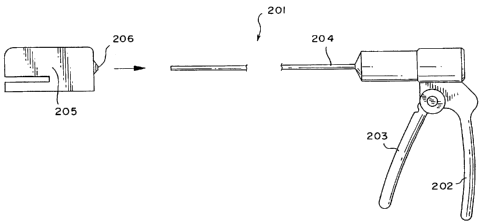
Referring to Figures 30 and 31 of the drawings, the
CA 02551424 1995-02-20
- 25 -
surgical instrument of the second aspect of the present
invention is indicated generally by reference numeral 201
and includes a handle 202 provided with a trigger 203 which
is pivotally connected to the handle 202. The instrument 201
also includes an elongate shaft 204 and a detachable
instrumentation head 205. The shaft 204 and instrumentation
head are detachably connectable together by attachment means
206. As shown in the drawings, the instrumentation head 205
is provided with a stapling device. Obviously, any
particular alternative surgical instrument such as a
forceps, for instance, may be provided on the
instrumentation head 205.
In use, the shaft 204 of the surgical instrument 201 is
inserted into the valve (not shown) on the trocar sleeve
which is indicated generally by reference numeral 210. The
shaft 204 is pushed through the barrel 211 of the trocar
sleeve 210 which is of approximately from 3 mm to 6 mm
internal diameter. In the prior art, the internal diameter
of the trocar barrel and the shaft 204 is typically up to 15
mm in diameter so as to accommodate an instrument head of
that size.
In use, the detachable instrumentation head 205 is held in
the hand of the surgeon and the appropriate instrumentation
head 205 provided with the required instrument is connected
to the shaft 204 by the attachment means 206. The trigger
203 is operated by the surgeon so as to control and
manipulate the stapling device provided on the detachable
instrumentation head 205.
It is to be understood that the attachment means 206 is
variable as are the dimensions of the instrumentation head
205 since the latter is not restricted by the dimensions of
the trocar sleeve 211.
CA 02551424 1995-02-20
- 26 -
Reference is now made to the surgical incise drape device
of the invention.
There are four general ways in which the incise drape can
be used:
1. The invention may be used as a means of attachment of
a device such as an access device or access port for use
in minimally invasive surgery such as described above on
which is applied a significant force from the gas pressure
that is applied once pneumoperitoneum is established; or
forces arising from the manipulation of those access ports
from the hand or instruments.
2. It may be used as a means of attachment to make
current devices such as the numerous cannula used in
minimally invasive surgery leak free - in this instance
the device can be made to fit over the current cannula
with an adhesive flange that will stick to the drape. It
would also serve the purpose of fixing those devices in
place so that they do not slide through the trocar wound
and be used when a surgeon desires to put into place a
smaller cannula that the wound would allow.
3. Furthermore, the invention can be used as a means to
apply an external pulling force on the patients skin and
attached tissue (subcutaneous tissue, muscle, Peritoneum)
for many purposes. One such purpose would be a gasless
means to lift the abdominal wall to create a cavity
similar to that created by pneumoperitoneum, or the
gasless "laprolift" that uses an internal device to lift
the abdominal wall for a gasless procedure. Another
purpose would be lifting the abdominal cavity to allow the
"first trocar" incision to make it safer. Also it could
CA 02551424 1995-02-20
- 27 -
be used as a tissue retractor, by pulling from the
attachment point(s) of the drape on both sides of a
surgical would, etc.
4. The incise drape could be also used in a situation
with a combination of gas and pull requiring less gas
pressure. Similar to 3 above, a means of pulling on the
attachment point(s) is used to reduce the amount of gas
pressure required to make a cavity for the purpose of the
minimally invasive surgery procedures. By way of example
if one was to pull on the hand access port included in our
previous patent application, less gas pressure would be
required to fi'' the body cavity to produce the same space
that is made f- pressure alone. As gas pressure has
some severe complications in selected patients, and is
often difficult to work with, this technique could be a
significant advantage in minimally invasive surgery, for
instance.
It will of course be understood that the invention is not
limited to the specific details described herein, which are
given by way of example only, and that various
modifications and alterations are possible within the scope
of the invention as defined in the appended claims.