Language selection

Search

Patent 2551577 Summary

Third-party information liability

Some of the information on this Web page has been provided by external sources. The Government of Canada is not responsible for the accuracy, reliability or currency of the information supplied by external sources. Users wishing to rely upon this information should consult directly with the source of the information. Content provided by external sources is not subject to official languages, privacy and accessibility requirements.

Claims and Abstract availability

Any discrepancies in the text and image of the Claims and Abstract are due to differing posting times. Text of the Claims and Abstract are posted:

  • At the time the application is open to public inspection;
  • At the time of issue of the patent (grant).
(12) Patent: (11) CA 2551577
(54) English Title: CONTAINER
(54) French Title: CONTENANT
Status: Deemed expired
Bibliographic Data
(51) International Patent Classification (IPC):
  • B65D 17/50 (2006.01)
  • B21D 51/38 (2006.01)
(72) Inventors :
  • DUNWOODY, PAUL ROBERT (United Kingdom)
  • MARRIOTT, PHILIP ALAN (United Kingdom)
  • NAYAR, SUDESH KUMAR (United Kingdom)
(73) Owners :
  • CROWN PACKAGING TECHNOLOGY, INC. (United States of America)
(71) Applicants :
  • CROWN PACKAGING TECHNOLOGY, INC. (United States of America)
(74) Agent: FETHERSTONHAUGH & CO.
(74) Associate agent:
(45) Issued: 2012-04-17
(86) PCT Filing Date: 2004-11-29
(87) Open to Public Inspection: 2005-07-14
Examination requested: 2009-11-26
Availability of licence: N/A
(25) Language of filing: English

Patent Cooperation Treaty (PCT): Yes
(86) PCT Filing Number: PCT/EP2004/013521
(87) International Publication Number: WO2005/063587
(85) National Entry: 2006-06-23

(30) Application Priority Data:
Application No. Country/Territory Date
03258228.0 European Patent Office (EPO) 2003-12-29

Abstracts

English Abstract


A container for food which is closed by a peelable membrane (2) at one end and
a sanitary end (4) at the opposite end. The container has a ring (1) to which
the membrane is fixed, the ring and sanitary end being formed from the same
sheet metal. In order to make this possible, the container body (3) flares
outwardly at the end to which the ring is fixed and is necked at the opposite
end. Dimensions are selected so that the resultant container is not only
stable but also readily handled during manufacture, filling and on supermarket
shelves.


French Abstract

La présente invention concerne un contenant pour aliment qui est fermé par une membrane pelable (2) au niveau d'une extrémité et une extrémité hygiénique (4) au niveau de son autre extrémité. Ce contenant comporte un anneau (1) auquel est fixé la membrane, cet anneau et l'extrémité hygiénique étant formés à partir de la même feuille métallique. Dans ce but, le corps du contenant (3) s'évase vers l'extérieur au niveau de l'extrémité à laquelle l'anneau est fixé et il se rétrécit au niveau de l'autre extrémité. Les dimensions sont choisies de sorte que le contenant résultant ne soit pas seulement stable mais également facilement manipulé au cours de sa fabrication, de son remplissage et de son stockage sur des étagères de supermarchés.

Claims

Note: Claims are shown in the official language in which they were submitted.


-6-
CLAIMS:

1. A metal container comprising a base, a side wall and a ring component
which is adapted to be closed by a peelable membrane or foil, the base and the
ring
component being formed from the same sheet metal,

in which the container side wall has a central section of substantially
constant cross-section,

the ring component fixed to an outwardly flared end of the container
side wall which is flared outwardly by between 6 mm and X mm, where X=0.15
times
a diameter D1 of the container side wall, and

the base is fixed to an inwardly tapered end of the container side wall
which is tapered inwardly by between 2 mm and Y mm, where Y = 0.22 times the
diameter D1 of the side wall.

2. A container according to claim 1, in which the difference between an
upper diameter D2 and the side wall diameter D1 is from 6 mm to 12 mm and the
difference between an end diameter D3 and the upper diameter D2 is
from 14 mm to 28 mm.

3. A container according to claim 2, in which the difference D2 - D1 is
between 10 mm and 11 mm and the difference D2 - D3 is between 23 mm
and 27 mm.

4. A container according to any one of claims 1 to 3, in which the ring
component includes a generally flat


-7-
panel to which a peelable membrane is fixable, the flat
panel having a seal width of 2 mm to 6 mm.

5. A container according to any one of claims 2 to 4,
in which the internal diameter of the ring component is
the same as or greater than the diameter D1 of the side
wall.

6. A container according to claim 5, in which the
diameter D3 is at least 15 mm smaller than the side wall
diameter D1.

7. A method of forming a container according to any one
of claims 1 to 6, the method comprising:
forming a cylindrical side wall;
expanding the side wall at one end and necking the
side wall at the opposite end;
forming an intermediate component having a seaming
panel connected by a wall to a flat annulus, a
substantially cylindrical wall portion and a centre
panel;
cutting the centre panel out of the intermediate
component and curling the cylindrical wall to form a ring
component;
seaming the ring component to the expanded end of
the side wall and the centre panel to the necked end.

8. A method according to claim 7, in which the step of
forming the intermediate component comprises forming can
end features on the centre panel.

Description

Note: Descriptions are shown in the official language in which they were submitted.


CA 02551577 2006-06-23
WO 2005/063587 PCT/EP2004/013521
CONTAINER
This invention relates to a metal container of the
type having a body which is closed at one end by a
peelable membrane or foil. In particular, it relates to a
can body having a separate member fixed to one end and to
which the peelable component is adhered.
The usage of the sheet metal from which a container
is manufactured is obviously of economic importance to
the industry. For example, when the sheet metal is
"blanked" to form ring-shaped components to which a
peelable component is applied, the material punched out
of the middle is often discarded. Systems which reuse
this blanked material in forming smaller sanitary (non-
processed) can ends have been implemented but are
inherently limited in the maximum size of ends which can
15, be produced. The size of the sanitary ends is also such
that they cannot be used on the same container as the
ring without the resultant container being "top-heavy"
and unstable. If the containers used for the ring and end
are manufactured in different volumes then there will
still be surplus of one of these and the manufacturing
and mechanical handling logistics become difficult.
This invention seeks to provide a stable container
which minimises metal usage and is readily handled during
manufacture, filling and on shop shelves.
According to the present invention, there is
provided a metal container comprising a base, a side wall
and a ring component which is adapted to be closed by a
peelable membrane or foil, the base and the ring
component being formed from the same sheet metal,


CA 02551577 2011-04-28
28589-79

-2-
in which the container side wall is flared outwardly at the end to which
the ring component is fixed by between 6 mm and X mm, where X = 0.15 times the
diameter of the container side wall, has a central section of substantially
constant
cross-section, and is tapered inwardly at the base by between 2 mm and Y mm,
where Y = 0.22 times the diameter of the side wall.

According to another aspect of the present invention, there is provided
a metal container comprising a base, a side wall and a ring component which is
adapted to be closed by a peelable membrane or foil, the base and the ring
component being formed from the same sheet metal, in which the container side
wall
has a central section of substantially constant cross-section, the ring
component fixed
to an outwardly flared end of the container side wall which is flared
outwardly by
between 6 mm and X mm, where X =0.15 times a diameter D, of the container side
wall, and the base is fixed to an inwardly tapered end of the container side
wall which
is tapered inwardly by between 2 mm and Y mm, where Y = 0.22 times the
diameter
D1 of the side wall.

Typical examples of X and Y are therefore X = 11 mm and Y = 16 mm
for a 73 mm can side wall diameter, although different can bodies diameters
may also
be used. Although a side wall diameter of 150 mm is currently the largest
which is
likely to be used with this invention, the invention is clearly not limited in
this respect.

The preferred range of flare and/or taper angle is 20 to 50 so as to
minimise the length of material to be formed without compromising axial
strength.
The maximum amount of flare for the upper end of the container is
selected as that which provides ease of filling without risking handling
difficulties on
the manufacturing line or supermarket shelves. The maximum taper at the bottom
end is that which is possible without risk of instability of the container.
However, a
minimum amount of flare/taper is required if the ring component and base are
to be
manufactured from the same sheet metal.


CA 02551577 2011-04-28
28589-79

- 2a -

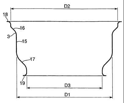
In a typical cylindrical container to hold between 80g and 500g of food
the difference between upper diameter D2 and the side wall diameter D, is from
6 mm
to 12 mm and the difference between the end diameter D3 and the upper diameter
D2
is from 14 mm to 28 mm. Preferably,


CA 02551577 2006-06-23
WO 2005/063587 PCT/EP2004/013521
-3-
the difference D2 - D1 is between 10 mm and 11 mm and the
difference D2 - D3 is between 23 mm and 27 mm.

The ring component may generally include a flat
panel to which a peelable membrane is fixable, the flat
panel preferably having.a seal portion with a width of 2
to 6 mm. The cut edge of the ring portion may be curled
either outwardly or inwardly so as to hide the cut edge.
For optimum product release, particularly when the
product is solid, such as pet food, the internal diameter
of the ring component for a cylindrical container may be
the same as or greater than the diameter D1 of the side
wall.
For such products which need to be easily removed,
the diameter D3 is ideally at least 15 mm smaller than
the side wall diameter D1 since this enables a ring
component to be manufactured from the same material as
the base, but having an internal ring diameter which is
greater than or equal to'the side wall diameter.
According to a further aspect of the present
invention, there is provided a method of forming a
container comprising: forming a cylindrical side wall;
expanding the side wall at one end and necking the side
wall at the opposite end; forming an intermediate
component having a seaming panel connected by a wall to a
flat annulus, a substantially cylindrical wall portion
and a centre panel; cutting the centre panel out of the
intermediate component and curling the cylindrical wall
to form a ring component; seaming the ring component to
the expanded end of the side wall and the centre panel to
the necked end.


CA 02551577 2006-06-23
WO 2005/063587 PCT/EP2004/013521
-4-
The step of forming the intermediate component may
comprise forming can end features on the centre panel.
A preferred embodiment of the invention will now be
described, by way of example only, with reference to the
drawing which is a schematic side view of one progression

of forming a ring component and can end for seaming to
the same can body.
Figure 1 shows a ring 1 for closing by a peelable
foil or membrane 2, a can body 3 and sanitary end 4. With
reference to figure 1(a) to 1(c), ring 1 and end 4 are
formed from the same sheet metal 5 by drawing the metal
sheet into a shallow cup 6 with flat annular portion 7
and wall 8 extending into a seaming panel 9 and
terminating in curl 10. Base 11 of the cup 6 is severed
close to the cup wall 12 so as to form a stepped disc 13
which is subsequently to.be used for forming the base of
the container. The wall 12 is then curled adjacent
annulus 7, thus forming a bond surface for fixing foil 2.
In the figure 1(c) this bonding surface 7 is shown as
flat but it may be inclined if desired for pressure
performance purposes, for example. In one embodiment, a
tab 14 may be formed from the foil 2.
As shown in figure 1(d), the can body 3 is formed
from a cylinder of metal 15 which is expanded outwardly
at one end 16 and necked inwardly at the opposite end 17.
The body is provided with a flange 18, 19 at each end
suitable for seaming the ring component 1 and can end 4
respectively.


CA 02551577 2006-06-23
WO 2005/063587 PCT/EP2004/013521
-5-
Stepped disc 13, which was cut from the cup 6 (see
figure 1(a) and 1(b)) is shallow drawn, curled and then
seamed to the lower end of can body 3.
In accordance with the invention, the dimensions of
the features are selected so as to enable the ring 1 and
end 4 to be manufactured from a single sheet of metal. In
particular, dimensions are selected as defined in the
claims. One container made in accordance with the
invention has a 200 ml contained volume and has an 83 mm
diameter peel seam ring, 73 mm body diameter and 58 mm
diameter end. Another container had a 73 mm diameter
ring, 65 mm diameter body and 51 mm diameter end.
The example of the figure may be modified by forming
the steps in a series of simple forming operations or by
carrying out one or more of the steps in a single
machine. Furthermore, different shapes of formed
components may be made so as to allow, say, the lower
side of the sheet metal 5 to become the upper side of the
ring 1 whilst remaining the lower side of end 4. This is
particularly useful where the coating on one side is a
"soft" material selected for bonding the peelable foil'to
the ring, but a more robust material is preferred for the
end which is in contact with the product.

Representative Drawing
A single figure which represents the drawing illustrating the invention.
Administrative Status

For a clearer understanding of the status of the application/patent presented on this page, the site Disclaimer , as well as the definitions for Patent , Administrative Status , Maintenance Fee  and Payment History  should be consulted.

Administrative Status

Title Date
Forecasted Issue Date 2012-04-17
(86) PCT Filing Date 2004-11-29
(87) PCT Publication Date 2005-07-14
(85) National Entry 2006-06-23
Examination Requested 2009-11-26
(45) Issued 2012-04-17
Deemed Expired 2015-11-30

Abandonment History

There is no abandonment history.

Payment History

Fee Type Anniversary Year Due Date Amount Paid Paid Date
Registration of a document - section 124 $100.00 2006-06-23
Application Fee $400.00 2006-06-23
Maintenance Fee - Application - New Act 2 2006-11-29 $100.00 2006-10-23
Maintenance Fee - Application - New Act 3 2007-11-29 $100.00 2007-10-22
Maintenance Fee - Application - New Act 4 2008-12-01 $100.00 2008-10-29
Maintenance Fee - Application - New Act 5 2009-11-30 $200.00 2009-10-23
Request for Examination $800.00 2009-11-26
Maintenance Fee - Application - New Act 6 2010-11-29 $200.00 2010-10-22
Maintenance Fee - Application - New Act 7 2011-11-29 $200.00 2011-10-24
Final Fee $300.00 2012-02-02
Maintenance Fee - Patent - New Act 8 2012-11-29 $200.00 2012-11-15
Maintenance Fee - Patent - New Act 9 2013-11-29 $200.00 2013-11-18
Owners on Record

Note: Records showing the ownership history in alphabetical order.

Current Owners on Record
CROWN PACKAGING TECHNOLOGY, INC.
Past Owners on Record
DUNWOODY, PAUL ROBERT
MARRIOTT, PHILIP ALAN
NAYAR, SUDESH KUMAR
Past Owners that do not appear in the "Owners on Record" listing will appear in other documentation within the application.
Documents

To view selected files, please enter reCAPTCHA code :


To view images, click a link in the Document Description column. To download the documents, select one or more checkboxes in the first column and then click the "Download Selected in PDF format (Zip Archive)" or the "Download Selected as Single PDF" button.

List of published and non-published patent-specific documents on the CPD .

If you have any difficulty accessing content, you can call the Client Service Centre at 1-866-997-1936 or send them an e-mail at CIPO Client Service Centre.


Document
Description 
Date
(yyyy-mm-dd) 
Number of pages   Size of Image (KB) 
Abstract 2006-06-23 2 70
Claims 2006-06-23 2 63
Drawings 2006-06-23 2 16
Description 2006-06-23 5 209
Representative Drawing 2006-06-23 1 4
Cover Page 2006-09-07 1 34
Description 2011-04-28 6 224
Claims 2011-04-28 2 61
Representative Drawing 2012-03-21 1 4
Cover Page 2012-03-21 1 33
PCT 2006-06-23 2 77
Assignment 2006-06-23 3 128
Prosecution-Amendment 2009-11-26 1 48
Prosecution-Amendment 2010-10-29 2 35
Prosecution-Amendment 2011-04-28 6 209
Correspondence 2012-02-02 2 62