Note: Descriptions are shown in the official language in which they were submitted.
CA 02551831 2006-06-27
WO 2005/072391 PCT/US2005/002632
SMALL VESSEL ULTRASOUND CATHETER
Priority Applications
This application claims the benefit of U.S. Provisional Application
60/539,954 (filed 29 January 2004; Attorney Docket EKOS.168PR) and U.S.
Provisional Application 60/570,969 (filed 14 May 2004; Attorney Docket
EKOS.168PR3). All of these priority applications are hereby incorporated by
reference herein in their entirety.
Field of the Invention
The present invention in certain embodiments relates generally to an
ultrasound catheter, and specifically to an ultrasound catheter having a
variable
flexibility along the catheter body.
Background of the Invention
Ultrasonic energy can be used to enhance the delivery and effect of various
therapeutic compounds. Often, an ultrasound catheter delivers ultrasonic
energy
and/or a therapeutic compound to a treatment site within a patient's
vasculature.
Such an ultrasound catheter typically comprises an elongate member configured
for advancement through a patient's vasculature. An ultrasound assembly is
mounted along the distal end portion of the elongate member and is adapted for
emitting ultrasonic energy. The ultrasound catheter can include a delivery
lumen
for delivering the therapeutic compound to the treatment site. In this manner,
ultrasonic energy can be delivered to the treatment site to enhance the effect
and/or delivery of the therapeutic compound.
For example, in one application, ultrasound catheters have been
successfully used to treat human blood vessels that have become occluded by
plaque, thrombi, emboli or other substances that reduce the blood carrying
capacity of the vessel. See, for example, U.S. Patent 6,001,069. To remove the
blockage, the ultrasound catheter is advanced through the patient's
vasculature to
deliver solutions containing dissolution compounds directly to the blockage
site.
To enhance the therapeutic effects of the dissolution compound, ultrasonic
energy
-1-
CA 02551831 2006-06-27
WO 2005/072391 PCT/US2005/002632
is emitted into the dissolution compound and/or the surrounding tissue. In
other
applications, ultrasound catheters can be used for other purposes, such as
delivering and activating light activated drugs with ultrasonic energy. See,
for
example, U.S. Patent 6,176,842.
Summar~i of the Invention
Generally, conventional ultrasound catheters are not well adapted for
effective use within small blood vessels, such as blood vessels located in the
distal
anatomy or in the brain. This is often the result of several factors. For
example,
the distal end portion of the catheter, on which the ultrasound assembly is
usually
located, is relatively rigid and therefore often lacks sufficient flexibility
for
navigation through difficult regions of the distal anatomy. In particular,
this distal
rigidity is generally attributable to the ultrasound radiating member mounted
in the
distal region of the catheter. Even in an ultrasound assembly having a single
ultrasound radiating member, the increased rigidity along the length of the
ultrasound radiating member can adversely effect catheter maneuverability.
Similarly, the minimum diameter vessel through which an ultrasound catheter
can
be passed depends, at least in part, on the outer diameter of the ultrasound
radiating member. Furthermore, various wires must extend through the catheter
to
provide power to the ultrasound radiating member. In addition, the ultrasound
catheter is typically provided with an inner member further increasing the
stiffness
of the catheter.
Furthermore, it is difficult to manufacture an ultrasound catheter having a
sufficiently small diameter for use in small vessels while still providing the
catheter
with adequate "pushability" and "torqueability" Likewise, it is difficult to
manufacture an ultrasound radiating member having sufficiently small
dimensions
for use in small vessels while still being capable of generating sufficient
quantities
of acoustic energy to enhance lysis at the treatment site. Still further, the
distal tip
of an ultrasound catheter can easily damage the fragile walls of small vessels
in
the patient's vasculature.
Accordingly, certain embodiments of an improved ultrasound catheter
disclosed herein are capable of safely and effectively navigating small blood
vessels, such as the main and subsequent branches of the middle cerebral
artery.
_2_
CA 02551831 2006-06-27
WO 2005/072391 PCT/US2005/002632
Such an improved catheter is also capable of delivering adequate ultrasonic
energy to achieve a desired therapeutic effect. The embodiments described
herein illustrate various features of such an improved ultrasound catheter.
One embodiment of the present invention comprises an ultrasound catheter
configured to be advanced into a patient's neurovascular system. The catheter
includes an elongate outer sheath and an elongate hollow inner core. The
elongate outer sheath defines a central lumen that extends longitudinally from
an
outer sheath proximal region to an outer sheath distal region. The elongate
hollow
inner core is positioned in the central lumen. The inner core defines a
utility lumen
configured to receive a guidewire. The inner core has a distal region that
terminates at a point that is proximal to the outer sheath distal region. The
inner
core comprises a reinforcing member that extends along at least a portion of
the
inner core. The reinforcing member is configured to reduce ovalization of the
inner
core as the catheter is bent. A tubular inner support member is coupled to the
inner core distal region. A tubular outer support member is coupled to the
outer
sheath distal region. An ultrasound radiating member has an inner passage. The
ultrasound radiating member is positioned generally the between the inner and
outer support members, such that the inner support member passes through the
hollow inner core and the outer support member is positioned over an outer
surface of the ultrasound radiating member.
Another embodiment of the invention comprises an neurovascular catheter.
The catheter includes a tubular body having a proximal end and a distal end.
The
tubular body comprises an inner tubular component and an outer tubular
component. The outer tubular component has a proximal region, a distal region
end and a lumen extending therethrough. The inner tubular component is
positioned within the lumen of the outer tubular component and extends from
the
proximal region to distal region of the outer tubular component. The inner
tubular
component forms, at least in part a utility lumen, that extends from proximal
end of
the tubular body to the distal end of the tubular body. The inner tubular body
is
formed at least in part from a composite tube comprising an inner member. A
reinforcing coil surrounds the inner member, and an outer member covers the
reinforcing coil. At least one ultrasound radiating member is positioned
generally
between the outer tubular component and the inner tubular component at the
-3-
CA 02551831 2006-06-27
WO 2005/072391 PCT/US2005/002632
distal end of the tubular body. A least one electrical wire is operatively
connected
to the ultrasound radiating member. The at least one electrical wire extends
at
least partially through a space between the outer tubular component and the
inner
tubular component.
Another embodiment of the invention comprises a catheter having a distal
end and a proximal end. The catheter comprises an elongate outer sheath and
an enlogate inner sheath. The elongate outer sheath has an exterior surface.
The
distal end portion of said outer sheath has an outer diameter of less than
about 5
French for advancement through a small blood vessel. The outer sheath defines
a
central lumen extending longitudinally therethrough. An elongate inner core
extends through said central lumen of said outer sheath and terminates at an
exit
port located at the distal end of the catheter. The inner core defines a
utility lumen
adapted to receive a guidewire lumen. An ultrasound member is positioned at
the
distal end of the catheter body generally between the outer sheath and the
inner
core. A guidewire is configured to be slideably received within the utility
lumen for
advancement of the catheter to a treatment site. The guidewire having a
diameter
that is less than or equal to about .017 inches. The catheter is configured
such
that the catheter can be subjected to a 180 degree bend having a radius of
less
than about 10mm while still permitting the catheter to slide over the
guidewire.
In one embodiment of the present invention, a method of manufacturing an
ultrasound catheter comprises providing an elongate outer sheath that defines
a
central lumen extending longitudinally from an outer sheath proximal region to
an
outer sheath distal region. The method further comprises providing a plurality
of
elongate electrical conductors within the central lumen. The method further
comprises positioning an elongate inner core in the central lumen, such that
the
plurality of electrical conductors are positioned between the inner core and
the
outer sheath. The method further comprises coupling a tubular inner support
member to a distal region of the elongate inner core. The method further
comprises mounting an ultrasound radiating member to the inner support member.
The ultrasound radiating member includes a hollow inner core through which the
inner support member is positioned. The method further comprises coupling a
tubular outer support member to a distal region of the elongate outer sheath.
The
-4-
CA 02551831 2006-06-27
WO 2005/072391 PCT/US2005/002632
tubular outer support member is positioned over an outer surface of the
ultrasound
radiating member.
Brief Description of the Drawings
FIGURE 1 is a side view of an ultrasound catheter that is particularly well
suited for insertion into small blood vessels of the human body.
FIGURE 2A is a cross-sectional view of a distal end of the ultrasound
catheter of FIGURE 1.
FIGURE 2B is a cross-sectional view of the ultrasound catheter of FIGURE
1 taken through line 2B-2B of FIGURE 2A.
FIGURE 3 is a fragmentary cross-sectional view of a catheter section
having a multi-layered section with a variable flexibility.
FIGURE 4 is a fragmentary cross-sectional view of a catheter section
having a multi-layered section with a substantially constant flexibility.
FIGURE 5 is a fragmentary cross-sectional view of a catheter section
having a multi-layered section with a partial spiral cut.
FIGURE 6 is a cross-sectional view of the interface between a catheter
distal end and a catheter junction section.
FIGURE 7A is a partial cutaway of a distal section of a catheter comprising
a woven, braided kink-resisting member.
FIGURE 7B is a partial cutaway of a distal section of a catheter comprising
a helically would coil kink-resisting member.
FIGURE 8 is an exploded view of the components comprising an ultrasound
catheter distal end and junction section.
FIGURE 9 is a side view of a catheter having a variable flexibility.
FIGURE 10 is a radial cross-sectional view of a distal portion of a catheter
having variable diameter stiffener strands and a variable outer diameter.
FIGURE 11 is a radial cross-sectional view of a midsection of a catheter
having variable diameter stiffener strands and a variable outer diameter.
FIGURE 12 is a radial cross-sectional view of a proximal portion of a
catheter having variable diameter stiffener strands and a variable outer
diameter.
-5-
CA 02551831 2006-06-27
WO 2005/072391 PCT/US2005/002632
FIGURE 13 is a radial cross-sectional view of a distal portion of a catheter
having variable diameter stiffener strands and a substantially constant outer
diameter.
FIGURE 14 is a radial cross-sectional view of a midsection of a catheter
having variable diameter stiffener strands and a substantially constant outer
diameter.
FIGURE 15 is a radial cross-sectional view of a proximal portion of a
catheter having variable diameter stiffener strands and a substantially
constant
outer diameter.
FIGURE 16 is a radial cross-sectional view of a distal portion of a catheter
having a variable thickness inner stiffener layer.
FIGURE 17 is a radial cross-sectional view of a midsection of a catheter
having a variable thickness inner stiffener layer.
FIGURE 18 is a radial cross-sectional view of a proximal portion of a
catheter having a variable thickness inner stiffener layer.
FIGURE 19 is a longitudinal cross-sectional view of a catheter 100
corresponding to the three radial cross sections of FIGURES 16 through 18.
FIGURE 20 is a longitudinal cross-sectional view of a catheter having a
non-discretely gradually increasing stiffness proximally.
FIGURE 21 is a radial cross-sectional view of a distal portion of a catheter
manufactured by stretching an extruded tubular member having a substantially
constant cross-sectional configuration, a first outer sheath material and a
second
stiffener strand material.
FIGURE 22 is a radial cross-sectional view of a midsection of a catheter
manufactured by stretching an extruded tubular member having a substantially
constant cross-sectional configuration, a first outer sheath material and a
second
stiffener strand material.
FIGURE 23 is a radial cross-sectional view of a proximal portion of a
catheter manufactured by stretching an extruded tubular member having a
substantially constant cross-sectional configuration, a first outer sheath
material
and a second stiffener strand material.
FIGURE 24 is a cross-sectional view of a catheter having a coaxial
segmented structure.
-6-
CA 02551831 2006-06-27
WO 2005/072391 PCT/US2005/002632
FIGURE 25 is an exemplary graph illustrating relative catheter flexibility as
a
function of axial catheter position.
FIGURE 26A is a partial cutaway side view of a composite tubular body with
improved flexibility and kink- and buckle-resistance.
FIGURE 26B is a cross-sectional view of the catheter of FIGURE 26A taken
along line 26B-26B.
FIGURE 27 is a cut-away view of selected internal components of a
backend hub configured for use with the composite tubular body of FIGURES 26A
and 26B.
FIGURE 28 is a cross-sectional view of the distal end of an ultrasound
catheter that includes the composite tubular body of FIGURES 26A and 26B.
FIGURE 29 is a cross-sectional view of a modified embodiment the distal
end of an ultrasound catheter.
Detailed Description of Preferred Embodiments
Introduction.
The advancement of an ultrasound catheter through a blood vessel to a
treatment site can be difficult and dangerous, particularly when the treatment
site
is located within a small vessel in the distal region of a patient's
vasculature.
Accessing the treatment site may involve navigating a tortuous path around
difficult bends and turns, such as the main and subsequent branches of the
middle
cerebral artery. During advancement through the vasculature, bending
resistance
along the distal end portion of the catheter can limit the ability of the
catheter to
make small radius turns. Moreover, as the catheter is advanced, the distal tip
of
the catheter is often in contact with the inner wall of the blood vessel. The
stiffness and rigidity of the distal tip of the catheter may lead to
significant trauma
or damage to the tissue along the inner wall of the blood vessel. As a result,
advancement of an ultrasound catheter through small blood vessels can be
extremely hazardous. Therefore, an improved ultrasound catheter design having
variable flexibility and/or stiffness along the length of the catheter body
will allow a
physician to more easily navigate difficult turns in small blood vessels while
reducing trauma and/or damage along the inner walls of the blood vessels.
-7-
CA 02551831 2006-06-27
WO 2005/072391 PCT/US2005/002632
Certain embodiments described herein provide an ultrasound catheter that
is well suited for use in the treatment of small blood vessels or other body
lumens
having a small inner diameter. Such embodiments can be used to enhance the
therapeutic effects of drugs, medication, pharmacological agents and other
therapeutic compounds at a treatment site within the body. See, for example,
U.S.
Patents 5,318,014; 5,362,309; 5,474,531; 5,628,728; 6,001,069; and 6,210,356.
Certain embodiments described herein are particularly well suited for use in
the
treatment of thrombotic occlusions in small blood vessels, such as, for
example, the
cerebral arteries. In addition, certain embodiments described herein can be
used in
other therapeutic applications, such as, for example, performing gene therapy
(see,
for example, U.S. Patent 6,135,976), activating light activated drugs for
producing
targeted tissue death (see, for example, U.S. Patent 6,176,842) and causing
cavitation and/or controlled cavitation to produce various desirable
biological effects
(see, for example, U.S. Patent RE36,939). Moreover, such therapeutic
applications
can be used in wide variety of locations within the body, such as, for
example, in
other parts of the circulatory system, in solid tissues, in duct systems and
in body
cavities. The ultrasound catheters disclosed herein, and variations thereof,
can be
used in other medical applications, such as, for example, diagnostic and
imaging
applications. The contents of the patents referenced above are hereby
incorporated by reference herein.
Ultrasound catheters and methods disclosed herein, and similar variations
thereof, can also be used in applications wherein the ultrasonic energy
provides a
therapeutic effect by itself. For example, ultrasonic energy can be effective
in
preventing and/or reducing stenosis and/or restenosis; causing tissue
ablation,
abrasion or disruption; promoting temporary or permanent physiological changes
in
intracellular or intercellular structures; and rupturing micro-balloons or
microbubbles
for drug delivery. See, for example, U.S. Patents 5,269,291 and 5,431,663,
which
are hereby incorporated by reference herein. In addition, the methods and
devices
disclosed herein can also be used in applications that do not require the use
of a
catheter. For example, the methods and devices disclosed herein can be used to
enhance hyperthermic drug treatment or to cause transdermal enhancement of the
therapeutic effects of drugs, medication, pharmacological agents, or other
therapeutic compounds at a specific site within the body. The methods and
_g_
CA 02551831 2006-06-27
WO 2005/072391 PCT/US2005/002632
devices disclosed herein can also be used to provide a therapeutic or
diagnostic
effect without the use of a therapeutic compound. See, for example, U.S.
Patents
4,821,740; 4,953,565; 5,007,438 and 6,096,000, the contents which are hereby
incorporated by reference herein.
As used herein, the term "ultrasonic energy" is used broadly, and includes
its ordinary meaning, and further includes mechanical energy transferred
through
pressure or compression waves with a frequency greater than about 20 kHz. In
one
embodiment, the waves of the ultrasonic energy have a frequency between about
500 kHz and about 20 MHz, and in another embodiment the waves of ultrasonic
energy have a frequency between about 1 MHz and about 3 MHz. In yet another
embodiment, the waves of ultrasonic energy have a frequency of about 3 MHz.
As used herein, the term "catheter" is used broadly, and include its ordinary
meaning, and further includes an elongate flexible tube configured to be
inserted
into the body of a patient, such as, for example, a body cavity, duct or
vessel.
As used herein, the term "therapeutic compound" refers broadly, in addition
to its ordinary meaning, to a drug, medicament, dissolution compound, genetic
material, or any other substance capable of effecting physiological functions.
Additionally, any mixture comprising any such substances is encompassed within
this definition of "therapeutic compound".
As used herein, the term "end" refers, in addition to its ordinary meaning, to
a region, such that "proximal end" includes "proximal region", and "distal
end"
includes "distal region".
As used herein, the term "proximal element joint" refers generally, and in
addition to its ordinary meaning, to a region where a proximal portion of an
ultrasound radiating member is attached to other components of an ultrasound
catheter.
Exemplary embodiments of an ultrasound, drug delivery cathefer.
FIGURES 1 through 2B illustrated an exemplary embodiment of an
ultrasound catheter 100 that is well suited for use within small vessels of
the distal
anatomy, such as the remote, small diameter blood vessels located in the
brain.
As shown in FIGURE 1 and 2A, the ultrasound catheter 100 generally
comprises a multi-component tubular body 102 having a proximal end 104 and a
_g_
CA 02551831 2006-06-27
WO 2005/072391 PCT/US2005/002632
distal end 106. The tubular body 102 and other components of the catheter 100
can be manufactured in accordance with any of a variety of techniques well
known
in the catheter manufacturing field. As discussed in more detail below,
suitable
material dimensions can be readily selected taking into account the natural
and
anatomical dimensions of the treatment site and of the desired percutaneous
access site.
The tubular body 102 can be divided into multiple sections of varying
stiffness. For example, a first section, which includes the proximal end 104,
is
generally more stiff than a second section, which lies between the proximal
end
104 and the distal end 106 of the catheter. This arrangement facilitates the
movement and placement of the catheter 102 within small vessels. A third
section, which includes at least one ultrasound radiating member 124, is
generally
stiffer than the second section due to the presence of the ultrasound
radiating
member 124.
In the exemplary embodiments described herein, the assembled ultrasound
catheter 100 has sufficient structural integrity, or "pushability," to permit
the
catheter to be advanced through a patient's vasculature to a treatment site
without
significant buckling or kinking. In addition, the catheter can transmit torque
(that is,
the catheter has "torqueability"), thereby allowing the distal portion of the
catheter
to be rotated into a desired orientation by applying a torque to the proximal
end
104.
Referring now to FIGURE 2A, the elongate flexible tubular body 102
comprises an outer sheath 108 positioned upon an inner core 110. In an
embodiment particularly well suited for small vessels, the outer sheath 108
comprises a material such as extruded Pebax°, polytetrafluoroethylene
("PTFE"),
PEEK, PE, polyimides, braided polyimides and/or other similar materials. The
distal end portion of the outer sheath 108 is adapted for advancement through
vessels having a small diameter, such as found in the brain. In an exemplary
embodiment, the distal end portion of the outer sheath 108 has an outer
diameter
between about 2 French and about 5 French. In another exemplary embodiment,
the distal end portion of the outer sheath 108 has an outer diameter of about
2.8
French. In an exemplary embodiment, the outer sheath 108 has an axial length
of
-10-
CA 02551831 2006-06-27
WO 2005/072391 PCT/US2005/002632
approximately 150 centimeters. In other embodiments, other dimensions can be
used.
In other embodiments, the outer sheath 108 can be formed from a braided
and/or coiled tubing comprising, for example, high or low density
polyethylenes,
urethanes, nylons, and so forth. Such a configuration enhances the flexibility
of
the tubular body 102. For enhanced pushability and torqueability, the outer
sheath
108 can be formed with a variable stiffness from the proximal to the distal
end. To
achieve this, a stiffening member can be included along the proximal end of
the
tubular body 102. In one exemplary embodiment, the pushability and flexibility
of
the tubular body 102 are controlled by manipulating the material and thickness
of
the tubular body 102, while the torqueability, kink resistance, distortion
(also
referred to as "ovalization") and burst strength of the tubular body 102 are
controlled by incorporation of braiding and/or coiling along or into the
tubular body
102.
In one particular embodiment, the outer tubular member 108 comprises a
PTFE layer that surrounds a Teflon inner layer. As mentioned above, the outer
tubular member 108 generally tapers from the proximal end to the distal end.
In
one embodiment, the proximal end of the outer member is reinforced with
reinforcement member (e.g., a stainless steel flat wire coil) positioned
between the
PTFE and Teflon layers. A Tensile fiber (e.g., Kevlar or Vectron) may also be
positioned between the layers to add tensile strength to the catheter.
The inner core 110 at least partially defines a delivery lumen 112. In an
exemplary embodiment, the delivery lumen 112 extends longitudinally along
substantially the entire length of the catheter 100. The delivery lumen 112
comprises a distal exit port 114 and a proximal access port 116. Referring
again
to FIGURE 1, the proximal access port 116 is defined by therapeutic compound
inlet port 117 of back end hub 118, which is attached to the proximal end 104
of
the other sheath 108. In an exemplary embodiment, the illustrated back end hub
118 is attached to a control box connector 120, which will be described in
more
detail below. In a modified embodiment, electronics and/or control circuitry
for
operating the ultrasound assembly are incorporated into the back end hub 118.
In an exemplary embodiment, the delivery lumen 112 is configured to
receive a guide wire (not shown). In one embodiment, the guidewire has a
-11-
CA 02551831 2006-06-27
WO 2005/072391 PCT/US2005/002632
diameter of approximately 0.008 inches to approximately 0.012 inches. In
another
embodiment, the guidewire has a diameter of about 0.010 inches. In an
exemplary embodiment, the inner core 110 comprises polyimide or a similar
material which, in some embodiments, can be braided and/or coiled to increase
the flexibility of the tubular body 102.
Referring now to the exemplary embodiment illustrated in FIGURES 2A and
2B, the distal end 106 of the tubular body 102 comprises an ultrasound
radiating
member 124. The ultrasound radiating member 124 can comprise an ultrasound
transducer that converts, for example, electrical energy into ultrasonic
energy. In a
modified embodiment, the ultrasonic energy can be generated by an ultrasound
transducer that is remote from the ultrasound radiating element 124, and the
ultrasonic energy can be transmitted via, for example, a wire to the
ultrasound
radiating member 124.
As illustrated in FIGURES 2A and 2B, the ultrasound radiating member 124
is configured as a hollow cylinder. As such, the inner core 110 can extend
through
the hollow core of the ultrasound radiating member 124. The ultrasound
radiating
member 124 can be secured to the inner core 110 in any suitable manner, such
as
with an adhesive. A potting material can also be used to further secure the
ultrasound radiating member 124 to the central core.
In other embodiments, the ultrasound radiating member 124 has different
shape. For example, the ultrasound radiating member 124 can be shaped as a
solid rod, a disk, a solid rectangle or a thin block. In still other
embodiments, the
ultrasound radiating member 124 comprises a plurality of smaller ultrasound
radiating elements. The embodiments illustrated in FIGURES 1 through 2B
advantageously provide enhanced cooling of the ultrasound radiating member
124. For example, in an exemplary embodiment, a therapeutic compound is
delivered through the delivery lumen 112. As the therapeutic compound passes
through the lumen of the ultrasound radiating member 124, the therapeutic
compound advantageously removes heat generated by the ultrasound radiating
member 124. In another embodiment, a return path can be formed in region 138
between the outer sheath 108 and the inner core 110 such that coolant from a
coolant system can be directed through region 138.
-12-
CA 02551831 2006-06-27
WO 2005/072391 PCT/US2005/002632
In an exemplary embodiment, the ultrasound radiating member 124 is
selected to produce ultrasonic energy in a frequency range adapted for a
particular
application. Suitable frequencies of ultrasonic energy for the applications
described herein include, but are not limited to, from about 20 kHz to about
20
MHz. In one embodiment, the frequency is between about 500 kHz and about 20
MHz, and in another embodiment, the frequency is between about 1 MHz and about
3 MHz. In yet another embodiment, the ultrasonic energy has a frequency of
about
3 MHz.
For example, in one embodiment, the dimensions of the ultrasound radiating
member are selected to provide a ultrasound radiating member that is capable
of
generating sufficient acoustic energy to enhance lysis without significantly
adversely
affecting catheter maneuverability.
As described above, in the embodiment illustrated in FIGURES 1 through
2B, ultrasonic energy is generated from electrical power supplied to the
ultrasound
radiating member 124. The electrical power can be supplied through control box
connector 120, which is connected to conductive wires 126, 128 that extend
through the tubular body 102. In another embodiment, the electrical power can
be
supplied from a power supply contained within the back end hub 118. The
conductive wires 126, 128 can be secured to the inner core 110, can lay along
the
inner core 110, and/or can extend freely in the region 138 between the inner
core
110 and the outer sheath 108. In the illustrated embodiments, the first wire
126 is
connected to the hollow center of the ultrasound radiating member 124, while
the
second wire 128 is connected to the outer periphery of the ultrasound
radiating
member 124. In an exemplary embodiment, the ultrasound radiating member 124
comprises a transducer formed of a piezoelectric ceramic oscillator or a
similar
material.
In the exemplary embodiment illustrated in FIGURES 2A and 2B, the distal
end 106 of the catheter 100 includes a sleeve 130 that is generally positioned
about
the ultrasound radiating member 124. In such embodiments, the sleeve 130
comprises a material that readily transmits ultrasonic energy. Suitable
materials
for the sleeve 130 include, but are not limited to, polyolefins, polyimides,
polyesters and other materials that readily transmit ultrasonic energy with
minimal
absorption of the ultrasonic energy. The proximal end of the sleeve 130 can be
-13-
CA 02551831 2006-06-27
WO 2005/072391 PCT/US2005/002632
attached to the outer sheath 108 with an adhesive 132. In certain embodiments,
to improve the bonding of the adhesive 132 to the outer sheath 108, a shoulder
127 or notch is formed in the outer sheath 108 for attachment of the adhesive
132
thereto. In an exemplary embodiment, the outer sheath 108 and the sleeve 130
have substantially the same outer diameter. In other embodiments, the sleeve
130 can be attached to the outer sheath 108 using heat bonding techniques,
such
as radiofrequency welding, hot air bonding, or direct contact heat bonding. In
still
other embodiments, techniques such as over molding, dip coating, film casting
and
so forth can be used.
Still referring to the exemplary embodiment illustrated in FIGURES 2A and
2B, the distal end of the sleeve 130 is attached to a tip 134. As illustrated,
the tip
134 is attached to the distal end of the inner core 110. In one embodiment,
the tip
is between about 0.5 millimeters and about 4.0 millimeters long. In another
embodiment, the tip is about 2.0 millimeters long. As illustrated, in certain
embodiments the tip is rounded in shape to reduce trauma or damage to tissue
along the inner wall of a blood vessel or other body structure during
advancement
toward a treatment site.
As illustrated in FIGURE 2B, the catheter 100 can include at least one
temperature sensor 136 along the distal end 106. In one embodiment, the
temperature sensor 136 is positioned on or near the ultrasound radiating
member
124. Suitable temperature sensors include but are not limited to, diodes,
thermistors, thermocouples, resistance temperature detectors, and fiber optic
temperature sensors that used thermalchromic liquid crystals. In an exemplary
embodiment, the temperature sensor 136 is operatively connected to a control
box
(not shown) through a control wire that extends through the tubular body 102
and
back end hub 118, and that is operatively connected to the control box via
control
box connector 120. The control box preferably includes a feedback control
system
having the ability to monitor and control the power, voltage, current and
phase
supplied to the ultrasound radiating member 124. In this manner, the
temperature
along the relevant region of the catheter 100 can be monitored and controlled.
Details of the control box can be found in Assignee's co-pending U.S. Patent
Applications 10/309,388 and 10/309,417, which are both incorporated by
reference
herein in their entirety.
-14-
CA 02551831 2006-06-27
WO 2005/072391 PCT/US2005/002632
In embodiments wherein multiple ultrasound radiating members are
positioned in the catheter distal region, a plurality of temperature sensors
can be
positioned adjacent to the ultrasound radiating members. For example, in one
such
embodiment, a temperature sensor is positioned on or near each of the multiple
ultrasound radiating members.
Exemplary Embodiments of Use
In an exemplary method, the ultrasound catheter 100 can be used to remove
an occlusion from a small blood vessel. In such an exemplary application, a
free
end of a guidewire is percutaneously inserted into a patient's vasculature at
a
suitable first puncture site. The guidewire is advanced through the
vasculature
toward a treatment site where the blood vessel is occluded by a thrombus. In
one
embodiment, the guidewire wire is directed through the thrombus, and is left
in the
thrombus during treatment to aid in dispersion of the therapeutic compound
into the
thrombus.
After advancing the guidewire to the treatment site, the catheter 100 is
percutaneously inserted into the patient's vasculature through the first
puncture site,
and is advanced along the guidewire towards the treatment site using
conventional
over-the-guidewire techniques. The catheter 100 is advanced until the distal
end
106 is positioned at or within the occlusion. In a modified embodiment, the
distal
end 106 comprises one or more radiopaque markers (not shown) to aid in
positioning the distal end 106 within the treatment site.
After the catheter is positioned, the guidewire can be withdrawn from the
delivery lumen 112. A therapeutic compound source (not shown), such as a
syringe
with a Luer fitting, is hydraulically connected to the therapeutic compound
inlet port
117 and the control box connector 120 is connected to the control box. Thus, a
therapeutic compound can be delivered through the delivery lumen 112 and out
the
distal exit port 114 to the occlusion. One exemplary therapeutic compound
appropriate for treating a thrombus is an aqueous solution containing heparin,
urokinase, streptokinase, and/or tissue plasminogen activator.
The ultrasound radiating member 124 can be activated to emit ultrasonic
energy from the distal end 106 of the catheter 100. As described above,
suitable
frequencies for the ultrasonic energy include, but are not limited to, from
about 20
kHz to about 20 MHz. In one embodiment, the frequency is between about 500 kHz
-15-
CA 02551831 2006-06-27
WO 2005/072391 PCT/US2005/002632
and about 20 MHz, and in another embodiment the frequency is between about 1
MHz and 3 MHz. In yet another embodiment, the ultrasonic energy has a
frequency
of about 3 MHz. The therapeutic compound and ultrasonic energy are applied
until
the thrombus is partially or entirely dissolved. Once the thrombus has been
dissolved sufficiently, the catheter 100 is withdrawn from the treatment site.
Methods of manufacture.
The catheters described herein can be manufactured by sequentially
positioning the various catheter components onto the catheter assembly. For
example, in one method of manufacture, the ultrasound radiating member 124 is
positioned around the outer surface of an intermediate portion of an elongate
tube.
The elongate tube serves as the inner core 110 and defines delivery lumen 112.
The first and second wires 126, 128 are then also disposed along the outer
surface of the inner core 110 proximal to the ultrasound radiating member 124.
The first wire 126 is electrically connected to an inner surface of the
ultrasound
radiating member 124, and the second wire is electrically connected to an
outer
surface of the ultrasound radiating member 124, as illustrated in FIGURE 2A.
The
electrical connections can be accomplished using, for example, a solder joint.
After the ultrasound radiating member 124 and wires 126, 128 are secured to
the inner core 110, an outer sheath 108 is positioned over a portion of the
inner
core, leaving the ultrasound radiating member 124 uncovered by the outer
sheath
108, as illustrated in FIGURE 2A. A cylindrical sleeve 130 is then positioned
over
the ultrasound radiating member 124, and is secured to the distal end of the
outer
sheath 108 with an adhesive 132. A rounded distal tip 134 can then be secured
to
the sleeve 130 and the inner core 110, and any excess length of the elongate
tube
extending distal to the distal tip 134 can be removed.
Although an exemplary catheter manufacturing technique has been
expounded above, other manufacturing techniques can be used, additional
components can be included, and the components set forth above can be
modified.
For example, in certain embodiments, the catheter 100 further comprises a
temperature sensor 136 positioned near the ultrasound radiating member 124, as
described above. In other embodiments, the outer sheath 108 can be modified to
-16-
CA 02551831 2006-06-27
WO 2005/072391 PCT/US2005/002632
manipulate the flexibility of the catheter 100, such as by including a
stiffening
component or metallic braiding and/or coiling.
Techniques to reduce buckling or kinking in an ultrasound, drug delivery
cathefer.
As described above, the ultrasound catheter should have sufficient
structural integrity, or "pushability," to permit the catheter to be advanced
through a
patient's vasculature to a treatment site without buckling or kinking.
Buckling and
kinking can obstruct the delivery lumen and cause excessive friction between
the
catheter and the blood vessel. In this section, several techniques are
described
for reducing the likelihood of buckling and kinking of the catheter with a
minimal
increase in the catheter stiffness by disposing a spirally cut thin polymeric
tubing in
regions the catheter body susceptible to buckling or kinking. Such regions may
in
the region of the proximally adjacent the ultrasound element.
FIGURE 3 illustrates a partial section of an outer sheath 108 (or inner core
110) that may be located proximal to the location of the ultrasound radiating
member, but that is still in a distal region of the catheter that is
susceptible to
buckling or kinking. As illustrated, in such embodiments, the outer sheath 108
may comprise an inner helically cut polymeric inner tubing stiffener member
202
and an outer polymeric layer 204.
In an exemplary embodiment, the inner tubing stiffener member 202
comprises a simple section of tubing that has been spirally cut from its inner
surface to its outer surface as shown in FIGURE 3. The spiral cut shown in
FIGURE 3 decreases in pitch in the distal direction to provide for a varying
amount
of flexibility in the distal direction. After it has been cut, the inner
tubing stiffener
member 202 is slightly stretched to provide increased flexibility. The inner
tubing
stiffener member 202 can comprise a wide variety of materials, such as linear
low
density polyethylene ("LLDPE") or low density polyethylene ("LDPE"). In
certain
embodiments, the inner tubing stiffener member 202 further comprises a small
amount of ethylene vinyl acetate ("EVA").
In an exemplary embodiment, the wall thickness of the outer sheath 108 is
between approximately 0.005 inches and approximately 0.002 inches. In another
embodiment, the wall thickness of the outer sheath 108 is approximately 0.0015
-17-
CA 02551831 2006-06-27
WO 2005/072391 PCT/US2005/002632
inches. The pitch of the cut in the inner tubing stiffener member 202 can be
of any
appropriate length. In a modified embodiment, the pitch of the cut in the
inner
tubing stiffener member 202 is variable, thereby providing a section of
varying
flexibility.
The outer polymeric layer 204 can comprise any of a wide variety of
materials. Such materials include, but are not limited to, Pebax°,
PTFE, PEEK,
PE, polyurethanes, polyvinyl chloride, LDPE, LLDPE, or mixtures thereof. In an
exemplary embodiment, the outer polymeric layer 204 comprises a heat
shrinkable
tubing of LDPE or LLDPE, having an EVA content of at least 10% EVA. In another
embodiment, the EVA content is between approximately 12% and approximately
20%. In another embodiment, the outer polymeric layer thickness is between
approximately 0.005 inches and approximately 0.010 inches. In still another
embodiment, the outer polymeric layer thickness is approximately 0.003 inches.
The aforementioned polymers can be cross-linked by radiation to increase their
strength and to promote heat shrinking.
The outer sheath illustrated in FIGURE 3 can be manufactured using a
variety of techniques, including the following exemplary technique. A distal
spacer
207 is placed on a mandrel of an appropriate size adjacent the inner stiffener
member 202. A proximal spacer 209 is also placed on the mandrel. An adhesive
such as thermoplastic can be applied to the outside of this assemblage but is
not
required. A heat shrinkable outer polymeric layer 204 is positioned over the
assemblage previously placed on the interior mandrel. The heat shrinkable
outer
polymeric layer 204 is then heat shrunk onto the assemblage. In an exemplary
embodiment, the material comprising the inner stiffener member 202 has a melt
temperature in the region of that of the heat shrink temperature of the heat
shrinkable outer polymeric layer 204. This creates a unitary structure having
a
high kink resistance and variable flexibility and pushability.
The outer polymeric layer 204 in FIGURE 3 can also be applied by dipping
the inner stiffener member 202 into a molten polymer bath or into a polymer
dissolved in a solution or into a suspension of latex comprising the outer
layer
polymer. The outer polymeric layer 204 can also be placed on the inner
stiffener
member 202 by spraying or otherwise applying the material. The catheters and
-18-
CA 02551831 2006-06-27
WO 2005/072391 PCT/US2005/002632
catheter sections described herein can be coated or otherwise treated both
inside
and outside to increase their lubricity.
FIGURE 4 illustrates a modified outer sheath 108. In such embodiments,
the spirally cut pitch is substantially constant, but otherwise the section is
identical
to that described in connection with FIGURE 3. This modified embodiment
provides kink resistance with enhanced flexibility.
FIGURE 5 illustrates a modified outer sheath 108 in which the spiral cut 242
is formed on only a portion of the interior stiffener member. In this
embodiment,
the spiral cut 242 provides an intermediate portion 234 having variable
flexibility,
positioned between a smaller diameter distal portion 232 and a larger diameter
proximal portion 236.
The outer sheath illustrated in FIGURE 5 can be manufactured using a
variety of techniques, including the following exemplary technique. The inner
stiffener member 238 comprises a polymer relatively stiffer than the outer
polymeric layer 240. In such embodiments, the inner stiffener member 238
comprises a polymer such as polypropylene, high density polyethylene ("HDPE"),
polyimides, polyamides (many of the nylons), and some of the stiffer grades of
polyethylene such as LLDPE and LDPE. The spiral cut 242 extends from the
outer surface of the inner stiffener member 238 to the inner surface of the
inner
stiffener member 238. In an exemplary embodiment, the spiral cut 242 is
slightly
expanded to provide a small gap therein. In such embodiments, the spiral cut
242
stops at the proximal end of the intermediate portion 234.
In one embodiment, the outer polymeric layer 240 comprises a heat-
shrinkable material such as a polyethylene. Other suitable materials for the
outer
polymeric layer 240 include polyurethane, polyvinyl chloride, and other softer
and
more compliant materials. In such embodiments, the outer polymeric layer 240
extends from the proximal end of the catheter to the distal end of the
catheter 230.
The embodiment illustrated in FIGURE 5 has a variety of advantages,
including ease of construction. For instance, the stiffener member 238
provides a
proximal portion 238 and an intermediate portion 234 that are easy to push and
that retain pushability while having less stiffness than more proximal
catheter
portions. The specific pattern of the spiral cut 242 in the inner stiffener
member
238 provides a smoother transition in stiffness between the proximal portion
236
-19-
CA 02551831 2006-06-27
WO 2005/072391 PCT/US2005/002632
and the distal portion 232 than does a section of tubing having an
intermediate
stiffness.
Braided catheter.
As described above, and as illustrated in FIGURE 1, certain ultrasound
catheter embodiments have a relatively more flexible distal end 106 and a
relatively less flexible proximal end 104. Such an arrangement increases
catheter
maneuverability to facilitate navigation of the catheter through the small
vessels of
a patient's vasculature. In particular, the relatively less flexible proximal
end 104 is
able to effectively transmit torquing and pushing operations during placement
of
the catheter. The ultrasound catheter 100 proximal end 104 and distal end 106
are joined at an intermediate junction section 306, which is illustrated in
greater
detail in FIGURE 6. Junction section 306 has an intermediate flexibility, and,
although forming only a small percentage of the overall length of the
catheter, is
nevertheless long when compared to the catheter diameter.
As illustrated in FIGURE 6, in an exemplary embodiment, the catheter distal
end 106 comprises a number of polymer layers and a kink-resisting member 320.
In certain embodiments, the catheter distal end 106 further comprises a
radiopaque band 308. The kink-resisting member 320 extends along at least a
portion of the distal end 106. The proximal end of kink-resisting member 320
is
also the proximal most extent of the distal end 106. Kink-resisting member 320
can comprise a woven braid 340 (as illustrated in FIGURE 7A) or can comprise
an
un-woven braid. The kink-resisting member 320 can also comprise a helically
wound coil 342, as illustrated in FIGURE 7B. The woven braid 340 can comprise,
for example, a pair of counter-woven helically wound coils such as described
as a
non-woven braid. Kink-resisting member 320 can comprise ribbons, wires,
individual fibers, accumulated fibers, woven fibers, or some combination
thereof.
As used herein, "ribbon", in addition to its ordinary meaning, further refers
to an
elongate element having a cross-section that is rectangular, oval or semi-
oval. In
an exemplary embodiment using the super-elastic alloys described below,
particularly those containing nickel and titanium, the thickness of a ribbon
used in
the kink-resisting member 320 is between approximately 0.00025 inches and
approximately 0.0025 inches, and the width a ribbon used in the kink-resisting
-20-
CA 02551831 2006-06-27
WO 2005/072391 PCT/US2005/002632
member 320 is between approximately 0.001 inches and approximately 0.010
inches. In an exemplary embodiment using metallic wire in the kink-resisting
member 320, the metallic wire has a diameter between approximately 0.00020
inches and approximately 0.002 inches. Generally, ribbons comprising suitable
polymers, such as liquid crystal polymers ("LCP"), are of a size similar to
those for
super-elastic alloys.
As noted above, the kink-resisting member 320 can comprise a super-
elastic alloy such as titanium/nickel materials known as nitinol. Commercial
nitinol
alloys containing up to about 8% or more of one or more of the members of the
iron group of the periodic table are considered to be encompassed within the
class
of super-elastic nickel/titanium alloys.
In certain embodiments where a super-elastic alloy is used to form the kink-
resisting member 320, after a braid has been woven using a plurality of
members,
a heat treatment is applied to the kink-resisting member. The heat treatment
reduces the likelihood that the braid will unravel during subsequent handling
or will
change in diameter or spacing during that handling. In the heat treatment, the
braids are placed on a heat-resistant mandrel, for example by weaving them
onto
that mandrel, and the mandrel in then placed in an oven at a elevated
temperature
for a few minutes. In one embodiment, the oven temperature is between
approximately 650 °F and approximately 750 °F. The heat
treatment anneals the
material comprising the ribbon and provides it with a reliable shape for
subsequent
assembly steps. After heat-treatment, the braid retains its shape and its
super-
elastic properties.
Although the ribbons comprising the kink-resisting member 320 described
above comprise a super-elastic alloy material, in other embodiments the
ribbons
comprise a braid made of a mixture of materials, such as a blend of super-
elastic
alloy and stainless steel components or of LCPs. Stainless steels and tungsten
alloys can also be used. In certain embodiments, particularly in smaller
diameter
devices, more malleable metals and alloys, such as gold, platinum, palladium,
rhodium, and so forth can be used. A platinum alloy with a few percent of
tungsten has high opacity to radio frequency energy. Non-metallic ribbons and
filaments can also be used; acceptable materials include, but are not limited
to,
-21-
CA 02551831 2006-06-27
WO 2005/072391 PCT/US2005/002632
high performance materials such as those made of polyaramids (for example,
Kevlar°), LCPs and carbon fibers.
As used herein, the term "woven braid", in addition to its ordinary meaning,
further includes tubular constructions in which the ribbons, wires, or
filaments
comprising the construction are woven radially in an in-and-out fashion as
they
cross each other to form a tubular member having a single lumen. For example,
the braid shown in FIGURE 7B has a nominal pitch angle of 45°. Other
braid
angles from less than 10° to more than 60° can also be used. In
other
embodiments, the pitch angle of the braid is varied, either when it is woven
or
when it is included in the catheter section. In an exemplary embodiment, the
innermost layer 322 has a smooth inner surface defining the delivery lumen.
The
delivery lumen and catheter axis 324 extends from the catheter distal end 106
to
the catheter proximal end. In innermost layer 322 can comprise, for example,
polymeric materials such as fluorocarbon polymers and lubricious polymers,
including PTFE, ethylene-chlorofluoroethylene ("ECTFE"), fluorinated ethylene
propylene ("FEP"), polychlorotrifluoroethylene ("PCTFE"), polyvinyl fluoride
("PVF")
or polyvinylidenefluoride ("PVDF"). Other materials such as polyethylene,
polypropylene, polyvinylchloride ("PVC"), EVA, polyurethanes, polyamides,
polyethyleneterephthalate ("PET"), polyamides (nylon) their mixtures, and co
polymers are also acceptable.
In certain embodiments wherein the innermost layer 322 comprises a
fluorinated polymer, the outside surface of the innermost layer 322 can be
etched
to provide a good mechanical surface to which adjacent polymers will readily
adhere. Certain procedures using, for example, treatment with a mixture of
aliphatic hydrocarbons and sodium metal as the etching solution is effective
in
such service.
The kink-resisting member 320 can be placed directly adjacent innermost
layer 322. In modified embodiments, kink-resisting member 320 is radially
encased by one or more layers, such as an inner filler layer 326 and an outer
filler
layer 328. In such modified embodiments, the likelihood of slip or shift of
the kink-
resisting member 320 against the typically lubricious innermost layer 322 can
be
reduced. The filler layers 126, 128 adhere to the kink-resisting member 320
and
form a determinate layer that enhances the kink-resisting capabilities of the
-22-
CA 02551831 2006-06-27
WO 2005/072391 PCT/US2005/002632
catheter distal end 106. To soften the outer surface of the distal end 106 and
to
lower the stiffness of the distal end 106, a distal outer shaft layer 330 is
placed on
the outside surface of the filler layers 126, 128. In certain embodiments, the
distal
outer shaft layer 330 extends for substantially the entire length of the
catheter
distal end 106. The filler layers 126, 128 can be configured as extensions of
tapered components of the assembly joint found in the junction section 306,
discussed in greater detail below. Distal most sections made in this way can
undergo bends of 1 /32 inch diameter without visible kinking.
In an exemplary embodiment, the filler layers 326, 328 are similar materials.
In one embodiment, the filler layers 326, 328 have a Shore hardness of
approximately 45 D to approximately 60 D. In another embodiment, the filler
layers 326, 328 have a Shore hardness of approximately 55 D. In one
embodiment, the distal outer shaft layer 330 is a second material having a
Shore
hardness of between approximately 70 A and approximately 85 A. In another
embodiment, the distal outer shaft layer 330 has a Shore hardness of
approximately 75 A. The filler layers 326, 328 and the distal outer shaft
layer 330
can comprise a variety of materials. In one embodiment, the filler layers 326,
328
and the distal outer shaft layer 330 comprise polymeric and selected other
materials that tend to tack to each other upon heating. Such materials can
also be
melt-miscible. In other embodiments, the filler layers 326, 328 and the distal
outer
shaft layer 330 contain ancillary components that act as adhesives. The
materials
comprising the filler layers 326, 328 and the distal outer shaft layer 330 can
be
made of heat-shrinkable materials (for example, irradiated low-density
polyethylene), or such materials can be otherwise placed onto the structure of
the
filler layers 326, 328 and the distal outer shaft layer 330. Examples of such
materials include polyurethanes and their alloys, mixtures, and co-polymers.
In
certain embodiments, the filler layers 326, 328 and the distal outer shaft
layer 330
comprise polymeric materials such as polyethylene, polypropylene, PVC, EVA,
polyurethanes, polyamides, PET, and their mixtures and co-polymers. In other
embodiments, the filler layers 326, 328 and the distal outer shaft layer 330
comprise mixtures of polyurethanes and polycarbonates sold as "Carbothane".
As described above, the junction section 306 is located proximal to the
distal end 106. The junction region 306 includes the region proximal to the
distal
-23-
CA 02551831 2006-06-27
WO 2005/072391 PCT/US2005/002632
end 106 that contains any tubing joint which has a tapering surface. FIGURE 6
illustrates a modified embodiment in which several tapering surfaces are
laminated
together to form a long junction region 306. In an exemplary embodiment, the
ratio of the length of the junction region to the diameter of the junction
region is
between approximately 12:1 and approximately 3:1. In another embodiment, the
ratio of the length of the junction region to the diameter of the junction
region is
between approximately 5:1 and approximately 2.5:1.
In an exemplary embodiment, and as illustrated in FIGURE 6, a first conical
layer 332 having a proximal male conical surface is positioned adjacent the
lubricious innermost layer 322. The first conical layer 322 can be an
extension of
inner filler layer 326. Likewise, a second conical layer 334 having a distal
female
conical surface that corresponds to the male surface on first conical layer
332. In
certain embodiments, second conical layer 334 further comprises a distal male
surface that corresponds to a proximal female conical surface on a third
conical
layer 336. In such embodiments, the third conical layer 336 is a proximal
extension of the outer filler layer 328. Likewise, the second conical layer
334 is a
distal extension of outer proximal layer 338. The outer proximal layer 338
comprises a material similar to the material found in the polymeric layers in
catheter the distal section, such as the filler layers 326, 326 and the distal
outer
shaft layer 330. In certain embodiments, the outer proximal layer 338
comprises a
material having a Shore hardness of between approximately 65 D and
approximately 85 D. In one embodiment, the outer proximal layer 338 comprises
a
material having a Shore hardness of between approximately 70 D and
approximately 75 D.
FIGURE 8 is an exploded view of the components comprising an exemplary
embodiment of the catheter distal end 106 and junction section 306. As
illustrated
in FIGURE 8, the lubricious innermost layer 322 is at least partially
surrounded by
inner filler layer 326, which includes the first conical layer 332. The kink-
resisting
member 320 is positioned on the exterior surface of inner filler layer 326.
Outer
filler layer 328 includes, in certain embodiments, third conical layer 336,
which
includes an internal female conical surface. As illustrated, outer filler
layer 328 is
positioned exterior to kink-resisting member 320. The distal outer shaft layer
330
is positioned still further exterior to the outer filler layer 328, and is
approximately
-24-
CA 02551831 2006-06-27
WO 2005/072391 PCT/US2005/002632
the same length as kink-resisting member 320. The outer proximal layer 338,
which includes a distally extending second conical layer 334, is illustrated
with both
a distal male conical surface and an inner female conical surface. In
embodiments
wherein the filler layers 326, 328 are extensions of the tapered components of
the
assembly joint, the filler layers 326, 328 will also be the distal ends of the
conical
members.
In certain embodiments, multiple polymeric layers are included in the
junction section 306 and the catheter distal end 106. In other embodiments, at
least one of the exterior and interior surfaces of the catheter are coated
with a
lubricious layer that is either chemically bonded to the surface or physically
coated
to the relevant catheter exterior surface. Exemplary procedures for producing
bonded lubricious coatings are described U.S. Patents 5,531,715 and 5,538,512.
The polymers noted herein can be filled with radiopaque materials such as
barium sulfate, bismuth trioxide, bismuth carbonate, powdered tungsten,
powdered
tantalum and so forth. In such embodiments, the location of the various
portions
of the catheter can be radiographically visualized in the human body.
In other embodiments, the pitch of kink-resisting member 320 varies within
the catheter distal end 106. In one such embodiment, the pitch of kink-
resisting
member 320 is greater towards the catheter distal end 106, thereby providing
enhanced flexibility in that region.
The components described herein that have tapering surtaces can be
manufactured by placing an appropriately sized tubing section on a mandrel
having the sought shape. The tubing section is then stretched until the sought
shape is achieved. The tubing section is then removed from the mandrel and is
2S cut to the appropriate size.
In an exemplary catheter assembly technique, the lubricious innermost layer
322 is placed on a mandrel and axially stretched to produce axial molecular
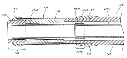
orientation. In an exemplary embodiment, the mandrel chosen provides an
appropriate change in the innermost layer 322 inner diameter, as described
above.
The catheter elements are then assembled as illustrated in FIGURE 8. A heat
shrinkable tubing is then placed on the exterior of the catheter assembly and
shrunk down to maintain the catheter elements in position and retain their
position
as they are further heated to cause the various polymers to flow into each
other
-25-
CA 02551831 2006-06-27
WO 2005/072391 PCT/US2005/002632
and form the conical surfaces as shown in FIGURE 8. In some embodiments, the
conical surfaces will not have the straight line interfaces illustrated in
FIGURE 8.
In such embodiments, a significant amount of curvature may exist within the
junction region.
Techniques for producing variable flexibility.
As described above, providing a ultrasound catheter with a variable
flexibility can enhance maneuverability of the catheter through small vessels
of a
patient's vasculature. In particular, in certain embodiments a proximal region
of
the catheter has decreased flexibility to enhance pushability, torqueability
and
kink-resistance, while a distal region of the catheter has increased
flexibility to
allow the catheter to easily track a guidewire and to navigate small-radius
bends of
a patient's vasculature. Often, the distal end of an ultrasound catheter will
have
decreased flexibility in the region of the ultrasound radiating member.
FIGURE 9 illustrates a catheter 100 having a variable flexibility. The
catheter 100 has a small diameter distal end 106, a relatively larger diameter
proximal end 104, and a delivery lumen 112 extending from the distal end 106
to
the proximal end 104 of the catheter 100. The catheter 100 includes one of the
stiffening mechanisms illustrated in FIGURES 10 through 20, which varies the
stiffness of the catheter 100 along the length of the catheter 100, while
introducing
few, if any, discontinuous changes in flexibility of the catheter 100. In
certain
embodiments, the catheter 100 can be fitted with an ultrasound radiating
member
at its distal end, as illustrated in FIGURES 2A and 2B, but omitted in FIGURES
9
through 23 for clarity.
In the exemplary embodiment illustrated in FIGURES 9 through 12, the
outer diameter of the catheter 100 increases gradually from the distal end 106
to
the proximal end 104, while the delivery lumen 112 has a substantially
constant
diameter x. However, in certain embodiments the delivery lumen 112 is enlarged
near the proximal end 104 to facilitate loading of the guidewire. The delivery
lumen diameter x is between approximately 0.010 inches and approximately 0.020
inches, thereby allowing it to accommodate and closely fit standard and
nonstandard sized guidewires. In such embodiments, the outer diameter of the
catheter 100 is just slightly larger than the delivery lumen diameter x, from
-26-
CA 02551831 2006-06-27
WO 2005/072391 PCT/US2005/002632
between approximately 0.025 inches and approximately 0.032 inches at the
distal
end 106, and gradually increasing to between approximately 0.030 inches and
approximately 0.040 inches at the proximal end. In one embodiment, the outer
diameter of the catheter 100 at the proximal end 104 is approximately 0.035
inches. As described above, the length of the catheter 100 can vary from less
than approximately 60 cm to more than approximately 175 cm, depending on the
application.
The exemplary embodiment illustrated in FIGURES 9 through 12 comprises
one or more stiffener strands 150. The distal cross section corresponding to
line
d-d of FIGURE 9 is shown in FIGURE 10. As shown in FIGURE 10, the outer
sheath 108 comprises most of the overall catheter cross section at the distal
end
106. At the catheter distal end 106, the stiffener strands 150 are small
relative to
the thickness of the outer sheath 108. In certain embodiments, the stiffener
strands 150 taper away completely and disappear proximal to the ultrasound
radiating member (not shown). For example, in one embodiment, the stiffener
strands 150 end at a point approximately 30 cm proximal to the ultrasound
radiating member.
The diameter of the delivery lumen 112, x, can vary depending on several
factors, including the size of the guidewire to be used with the catheter. In
FIGURE 11, which shows the radial cross section of a midsection of the
catheter
along line m-m, the outer diameter of the outer sheath 108 is slightly larger
than
that at the catheter distal end 106. The stiffener strands 150 at the
midsection are
also slightly larger than at the catheter distal end 106. In FIGURE 12, which
shows the radial cross section of the proximal end of the catheter along line
p-p,
the outer diameter of the outer sheath 108 is still larger than at the
midsection of
the catheter, and the stiffener strands 150 are also larger. In certain
embodiments, the stiffener strands 150 are sufficiently large such that they
fuse
together to form an intramural ring within the outer sheath 108.
In an exemplary embodiment, both the tubular body 108 and the stiffener
strands 150 comprise polymers, including thermoplastics such as LDPE, HDPE,
polypropylene, polystyrene, polyurethanes, polyesters (including nylon),
polyfluorocarbons, and polyolefin. In other embodiments, the tubular body 108
and the stiffener strands 150 comprise composite materials, blends, and
-27-
CA 02551831 2006-06-27
WO 2005/072391 PCT/US2005/002632
copolymers of the aforementioned compounds. For example, in one embodiment,
the stiffener strands 150 comprise a material having a stiffness greater that
the
stiffness of the outer sheath 108. In such embodiments, the two materials can
be
miscible, such that the stiffener strands 150 will melt into the outer sheath
108
when extruded, and will form a catheter body without distinct boundaries
between
the stiffener strands 150 and the outer sheath 108.
In one exemplary embodiment, the catheter comprises an outer sheath 108
made of LDPE and polyolefin (ethylene octane) in approximately equal portions,
and stiffener strands 150 made of a higher stiffness material, such as HDPE.
The
materials comprising the catheter can vary according to the intended use, and
many other plastics and composite materials, and even metals, can be used. For
example, in one embodiment, the outer sheath 108 comprises LDPE, and the
stiffener strands 150 comprise HDPE, LDPE, or a mixture of the two.
In a modified embodiment, the relative stiffness of the materials comprising
the outer sheath 108 and the stiffener strands 150 is reversed, with the outer
sheath 108 comprising the stiffer material, and the stiffener strands 150
comprising the more flexible material. In such embodiments, the stiffener
strands
150 will be thicker at the catheter distal end 106 and thinner at the catheter
proximal end 104, thereby providing the catheter with increasing flexibility
distally.
FIGURES 13 through 15 illustrate the distal, midsection, and proximal cross
sections of a catheter having variable diameter stiffener strands 150 and a
substantially constant outer diameter. The stiffener strands 150 increase in
thickness from the distal cross section d-d of FIGURE 13 to the proximal cross
section p-p of FIGURE 15, but the outer diameter of the outer sheath 108
remains
substantially constant along the length of the catheter. The inner diameter x
of the
delivery lumen 112 also remains substantially constant along the length of the
catheter. Accordingly, as the quantity of stiffener strand material decreases
from
the catheter proximal end 104 to the catheter distal end 106, the quantity of
outer
sheath material increases by approximately the same quantity.
FIGURES 16 through 18 illustrate the distal, midsection, and proximal cross
sections of a catheter having a variable thickness inner stiffener layer. In
such
embodiments, rather than using stiffener strands of increasing thickness
proximally, an inner stiffener layer 152 having a gradually increasing
thickness
-28-
CA 02551831 2006-06-27
WO 2005/072391 PCT/US2005/002632
proximally is used. The outer sheath 108 is more flexible than the inner
stiffener
layer 152. In one embodiment, the outer layer 108 comprises, for example, LDPE
or a mix of LDPT and polyolefin, and the inner stiffener layer 152 comprises,
for
example, HDPE. A comparison of the thicknesses of the inner stiffener layers
152
illustrated in FIGURES 16 through 18 reveals that the inner stiffener layer
152
becomes gradually thicker and comprises a larger portion of the catheter wall
from
the distal cross section d-d to the proximal cross section p-p. FIGURE 19
illustrates the longitudinal cross section of a catheter 100 corresponding to
the
three radial cross sections of FIGURES 16 through 18. As illustrated, the
thickness of inner stiffener layer 152 gradually increases from the catheter
distal
end 106 to the catheter proximal end 104. As described above, such a catheter
can have a substantially uniform outer diameter along its length, or it can
have an
outer diameter that increases toward the catheter proximal end. In certain
embodiments, the catheter distal end 106 can include a segment adjacent the
ultrasound radiating member (not shown) where the inner stiffener layer 152 is
absent.
FIGURE 20 illustrates a catheter having a non-discretely gradually
increasing stiffness proximally. Specifically, no discrete stiffener strands
are
present in this embodiment. Instead, the composition of the outer sheath 108
gradually changes along the length of the catheter from a first material to a
second
material. For example, in the catheter distal end 106, the outer sheath 108
comprises a more flexible material, for example LDPE, and in the catheter
proximal end 104, the outer sheath 108 comprises a less flexible material,
such as
HDPE. Between the distal and proximal ends, the composition of the outer
sheath
108 gradually changes from one material to another (for example, from
predominantly LDPE to predominantly HDPE). The stippling shown in the cross
section of FIGURE 12 indicates the gradual transition of the catheter wall
from
LDPE to HDPE.
In modified embodiments, the catheters described herein can further
include one or more radiopaque markers to assist in positioning the catheter
in,
and navigating the catheter through, a patient's vasculature.
The catheters described herein can be used in the highly tortuous blood
vessels of the body, including the coronary blood vessels, renal blood
vessels, and
_29_
CA 02551831 2006-06-27
WO 2005/072391 PCT/US2005/002632
intracranial blood vessels. As used herein, the term "highly tortuous" refers,
in
addition to its ordinary meaning, to the tortuosity typically encountered in
the
vascular pathway from a remote access site such as the femoral artery to
target
sites deep within the coronary, renal sinus and cerebral vasculature. Specific
catheter embodiments can be constructed for access into targeted sites
involving
pathologically tortuous blood vessels. As used herein, the term "pathological
tortuosity" refers, in addition to its ordinary meaning, to the vascular
pathway from
a remote access site such as the femoral artery to target sites involving (a)
turns in
excess of 90°, such as encountered when branching from one blood vessel
to
another blood vessel (that is, paths that branch off the preceding vessel at
angles
greater that a right angle), and (b) a total path length within the target
tissue at
least approximately 5 cm. Pathological tortuosity includes treatment sites
accessible by a guidewire approximately 0.018 inches or smaller.
The variable flexibility catheters described herein can be used with a
guidewire, although a guidewire is not required. The catheter flexibility can
be
varied to allow the catheter to be guided to the treatment site in a flow
directed
manner, or through manual steering. The materials and dimensions described
herein can be varied so that the catheter can be used in highly tortuous
pathways
with or without a guidewire. The variable flexibility catheters described
herein can
increase catheter maneuverability despite the presence of a relatively rigid
ultrasound radiating member at the distal end of the catheter.
The variable flexibility catheters described herein can be manufactured
using various known extrusion methods. Known methods of co-extrusion,
including for example cross header arrangements, over-extrusion, and extrusion
die construction can be applied to manufacture these catheters. Stiffener
strand
thickness, wall thickness, and relative percentage of outer sheath composition
can
be controlled with known techniques including for example speed controlled
extrusion, throttled flow controlled extrusion, and waste-gating. The
materials
disclosed herein can be used in catheter fabrication, but it is expected that
new
and improved materials will also be applied in the construction of the
catheters
disclosed herein.
For example, in one exemplary method of manufacture, a catheter is
manufactured by an extrusion method in which the tubular catheter having a
-30-
CA 02551831 2006-06-27
WO 2005/072391 PCT/US2005/002632
plurality of stiffener strands is co-extruded from a first material forming
the outer
sheath 108, and a second material forming the stiffener strands 150. The
diameter of the stiffener strands 150 can be varied during the extrusion
process to
form a catheter having a changing flexibility along its length.
In another exemplary method of manufacture, the catheter is extruded as a
tubular member having a substantially constant cross-sectional configuration
that
includes a first outer sheath material and a second stiffener strand material.
The
extruded tubular member having a substantially constant cross-sectional
configuration is then heated and stretched to a final configuration in which
the
catheter distal end is smaller in diameter and more flexible than the catheter
proximal end. The cross sections of a distal, intermediate, and proximal
portion of
a catheter formed by this method are illustrated in FIGURES 21 through 23,
respectively. As illustrated, as the catheter is stretched, the stiffener
strands 150
decrease in diameter and move closer together. The overall dimensions of the
catheter decrease distally. In one embodiment, the stiffener strands 150
contact
each another and melt together into an inner stiffener layer at the catheter
distal
end as the catheter is stretched.
Multi-Segment Catheter.
As described above, providing a ultrasound catheter with a variable
flexibility can enhance maneuverability of the catheter through small vessels
of a
patient's vasculature. In particular, in certain embodiments a proximal region
of
the catheter has decreased flexibility to enhance pushability, torqueability
and
kink-resistance, while a distal region of the catheter has increased
flexibility to
allow the catheter to easily track a guidewire and to navigate small-radius
bends of
a patient's vasculature. Often, the distal end of an ultrasound catheter will
have
decreased flexibility in the region of the ultrasound radiating member.
FIGURE 24 illustrates an intermediate portion of catheter having a variable
stiffness along its axial length. Such a catheter can be used to deliver an
ultrasound radiating member to a treatment site within a patient's
vasculature. In
the exemplary embodiment illustrated in FIGURE 24, the catheter comprises an
outer tube 918 and three coaxial inner tubular segments 919, 920, 921. As
-31-
CA 02551831 2006-06-27
WO 2005/072391 PCT/US2005/002632
illustrated, the three coaxial inner tubular segments 919, 920, 921 are
disposed in
tandem within the outer tube 918, and are contiguous to each other.
The outer tube 918 extends over substantially the entire length of the
catheter, which can be over approximately 50 cm, and is between approximately
80 cm and approximately 150 cm in certain embodiments. (As described above, in
certain embodiments the outer tube 918 does not cover an ultrasound radiating
member positioned at the catheter distal end.) The outer diameter of outer
tube
918 (as measured at the catheter proximal end) can be between approximately
0.75 mm and 2.00 mm, and is between approximately 0.85 mm and 1.30 mm in
certain embodiments. In a modified embodiment, the outer tube 918 necks down
at its distal end, such that its outer diameter at the distal end is slightly
smaller
than at its proximal end. The outer tube 918 can have a wall thickness of
between
approximately 0.08 mm and approximately 0.16 mm, and has a wall thickness of
between approximately 0.10 mm and approximately 0.13 mm in certain
embodiments. In an exemplary embodiment, the outer tube 918 comprises a
polymer having a flexural modulus (as measured by ASTM D-790) of between
approximately 100,000 kPa and approximately 250,000 kPa, such as low density
polyethylene.
In the exemplary embodiment illustrated in FIGURE 24, the proximal inner
tubular segment 919 extends from the catheter proximal end to proximal
junction
922. In one embodiment this distance is between approximately 10 cm and
approximately 70 cm, in another embodiment this distance is between
approximately 40 cm and approximately 60 cm, and in yet another embodiment
this distance is approximately 50 cm. In one embodiment the wall thickness of
the
proximal inner tubular segment 919 is between approximately 0.08 mm and
approximately 0.18 mm, and in 'another embodiment the wall thickness of the
proximal inner tubular segment 919 is between approximately 0.10 and
approximately 0.13 mm. In one embodiment, the proximal inner tubular segment
919 comprises a polymer having a flexural modulus of between approximately
1,500,000 kPa and approximately 1,800,000 kPa, such as polypropylene. Thus, in
such embodiments, the portion of the catheter between the catheter proximal
end
and the proximal junction 922 is relatively stiff. In one embodiment, the
inner
-32-
CA 02551831 2006-06-27
WO 2005/072391 PCT/US2005/002632
diameter of the proximal inner tubular segment 919 is between approximately
0.45
mm and approximately 0.75 mm.
Referring still to the exemplary embodiment illustrated in FIGURE 24,
intermediate inner tubular segment 920 extends from proximal junction 922 to
intermediate junction 923. In one embodiment the length of the intermediate
inner
tubular segment 920 is between approximately 30 cm and approximately 100 cm,
in another embodiment the length of the intermediate inner tubular segment 920
is
between approximately 70 cm and approximately 90 cm, and in yet another
embodiment the length of the intermediate inner tubular segment 920 is
approximately 80 cm. In an exemplary embodiment, the intermediate inner
tubular
segment 920 is less stiff than proximal inner tubular segment 919.
Accordingly,
the wall thickness of the intermediate inner tubular segment 920 is less than
the
wall thickness of proximal inner tubular segment 919. For example, the
intermediate inner tubular segment 920 can comprise a polymer having a lower
flexural modulus than the polymer comprising the proximal inner tubular
segment
919. In a modified embodiment, the intermediate inner tubular segment 920
comprises the same polymer as the proximal inner tubular segment 919, but has
a
smaller wall thickness. In one embodiment the intermediate inner tubular
segment
920 has a wall thickness of between approximately 0.05 mm and approximately
0.13 mm, and in another embodiment the intermediate inner tubular segment 920
has a wall thickness of between approximately 0.05 mm and approximately 0.08
mm. In an exemplary embodiment, the inner tubular segments 919, 920 can
comprise a continuous length of tubing having an appropriately tapered outer
diameter.
The distal inner tubular segment 921 extends from intermediate junction
923 to a location 924 proximal to the distal end of the catheter. For example,
in
one embodiment, location 924 can be adjacent the proximal end of an ultrasound
radiating member. In one embodiment the length of the distal inner tubular
segment 921 is between approximately 5 cm and approximately 20 cm, in another
embodiment the length of the distal inner tubular segment 921 is between
approximately 7 cm and approximately 15 cm, and in yet another embodiment, the
length of the distal inner tubular segment 921 is approximately 10 cm.
-33-
CA 02551831 2006-06-27
WO 2005/072391 PCT/US2005/002632
Based on the foregoing, in an exemplary embodiment, the distance from
proximal junction 922 to the distal end of the catheter will be greater than
approximately 50% of the entire length of catheter. In another embodiment, the
distance from proximal junction 922 to the distal end of the catheter will be
greater
than approximately 60% of the entire catheter length. In such embodiments,
distal
inner tubular segment 921 is less stiff than intermediate inner tubular
segment
920, and provides a transition in flexibility between inner tubular segment
920 and
the portion of the outer tube 918 that extends distal to location 924. In such
embodiments, the wall thickness of distal inner tubular segment 921 (a) is
less
than that of intermediate inner tubular segment 920, and/or (b) comprises a
polymer having a lower flexural modulus than the polymer comprising
intermediate
inner tubular segment 920. For example, in one embodiment, distal inner
tubular
segment 921 comprises a polymer having a flexural modulus that is (a)
significantly lower than the polymer comprising intermediate inner tubular
segment
920 but (b) higher than the polymer comprising the outer tube 918. The distal
inner tubular segment 921, for instance, can be linear, low density
polyethylene.
Typically, the flexural modulus of the polymer comprising distal inner tubular
segment 921 is between approximately 150,000 kPa and approximately 350,000
kPa. In one embodiment, , the flexural modulus of the polymer comprising
distal
inner tubular segment 921 is between approximately 200,000 kPa and
approximately 300,000 kPa. In one embodiment the wall thickness of distal
inner
tubular segment 921 is between approximately 0.05 mm and 0.10 mm, and in
another embodiment the wall thickness of distal inner tubular segment 921 is
between approximately 0.06 mm and 0.09 mm. In an exemplary embodiment, the
inner diameters of segments 920, 921 are substantially the same as that of
segment 919.
Although junctions 922, 923 are illustrated as butt joints in FIGURE 24,
these junctions can comprise other types of joints in other embodiments. For
example, in one other embodiment, junctions 922, 923 comprise overlap joints.
Thus, the catheter illustrated in FIGURE 24 comprises four segments of
different flexibility or stiffness, with the segments becoming increasingly
flexible
distally. This configuration provides a more gradual flexibility or stiffness
gradient
than a two-segment catheter. Specifically, the change in flexibility or
stiffness
-34-
CA 02551831 2006-06-27
WO 2005/072391 PCT/US2005/002632
between catheter segments in the embodiments described herein is not as great
in
a two-segment catheter. In particular, the catheter embodiments described
herein
allow the distal end of the catheter to be tracked around sharp bends in a
patient's
vasculature with less likelihood of kinking, despite the presence of a rigid
ultrasound radiating member located at the distal end of the catheter. The
multi-
segment configuration improves the ability of the catheter to track a
guidewire
around sharp bends, and reduces the likelihood of fatigue stress failure,
delamination, or other catheter structural failure. Such multi-segment
catheters
can be manufactured according to the catheter manufacturing techniques
disclosed herein.
Proximal element joint.
Several techniques for varying the flexibility, stiffness and other mechanical
properties of a catheter body are disclosed herein. As described elsewhere in
this
specification, in certain embodiments the catheter body is less flexible at
the
catheter proximal end, and gradually increases in flexibility toward the
distal end.
This configuration advantageously enhances catheter maneuverability by
facilitating the pushing, twisting or other motions used when advancing the
catheter over a guidewire and through a patient's vasculature to a treatment
site.
For example, a catheter with increasing distal flexibility often has enhanced
kink
resistance.
However, as described above, many of the techniques for manipulating the
mechanical properties of the catheters described herein can be used with a
catheter having one or more ultrasound radiating members mounted in a catheter
distal region. In such embodiments, the ultrasound radiating member acts as a
relatively stiff tip in the end region of an otherwise flexible catheter.
Thus, at the
proximal element joint there is a discontinuous change in flexibility from the
relatively flexibility distal region of the outer sheath to the relatively
rigid ultrasound
radiating member. As described previously, reducing the rigidity of the
proximal
element joint enhances the joint flexibility, reduces the likelihood of
kinking in the
catheter flexible support section, and facilitates tracking of the catheter
over the
guidewire.
-35-
CA 02551831 2006-06-27
WO 2005/072391 PCT/US2005/002632
Thus, in an exemplary embodiment, any of the techniques described herein
from introducing a gradually increasing flexibility from the catheter proximal
region
to the catheter distal region can also be used to introduce a variable
flexibility at
the proximal element joint. For example, the flexibility of the outer sheath
can
gradually decrease in a region proximal to the ultrasound radiating member,
thereby eliminating the discontinuous change in flexibility at the proximal
element
joint.
The relative catheter flexibility as a function of axial catheter position of
such an exemplary embodiment is illustrated in FIGURE 25. In particular,
FIGURE
25 illustrates the relative flexibility of an ultrasound catheter (on the y-
axis) at
various points along the catheter length (x-axis) between the catheter
proximal
region and the distal tip. As described above, in regions where the catheter
is
becoming more flexible distally, denoted as increasing flexibility region 160
in
FIGURE 25, any of the methods described herein for providing variable catheter
flexibility can be used.
Likewise, in the proximal element joint region 162, where the catheter is
becoming less flexible distally, any of the methods described herein for
providing
variable catheter flexibility can be used. Such methods include, but are not
limited
to, use of braids, compression regions, stiffener wires, and composite
materials.
Such methods can be employed to eliminate a discontinuous change in catheter
flexibility at the proximal element joint between the catheter distal region
and the
relatively rigid ultrasound radiating member region 164.
Still referring to FIGURE 25, the distal tip region 166, which is located
distal
to the ultrasound radiating member region 164, can be provided with an
increasing
flexibility to enhance maneuverability through the patient's vasculature.
FIGURE 25 represents an exemplary configuration of a variable flexibility
catheter. Other configurations can be used in other embodiments. For example,
in a modified embodiment, the catheter can have a relatively constant
flexibility
between the proximal region and the distal region, with a variable flexibility
at the
proximal element joint. Such an embodiment can comprise fewer components,
and thus have a reduced manufacturing cost. In still other embodiments, the
catheter can have a plurality of flexibility maxima and minima between the
catheter
proximal region and the catheter distal region, with such maxima and minima
-36-
CA 02551831 2006-06-27
WO 2005/072391 PCT/US2005/002632
positioned axially depending on the characteristics of the vasculature through
which the catheter is to be routed.
With continued reference to FIGURE 25, in one embodiment the ultrasound
radiating member region 164 comprises a portion that of the catheter that is
substantially unbendable during normal use conditions. In one embodiment, the
length of the ultrasound radiating member region 164 has a length that is less
than
about 6mm, in another embodiment, less than about 5 mm and, in yet another
embodiment, less than about 4 mm. In these embodiments, the ultrasound
radiating member region 164 has a length greater than about 3 mm such that
sufficient energy (i.e., ultrasound energy in the preferred embodiment) can be
delivered to the treatment site. Catheters with substantially unbendable
energy
delivery sections of longer lengths have difficulty effectively navigating
small blood
vessels, such as the main and subsequent branches of the middle cerebral
artery.
Delivery lumen with composite Tubing.
As described above, if the ultrasound catheter buckles or kinks during
advancement through the patient's vasculature, it may not be possible to
deliver
the ultrasound radiating member to the treatment site. With respect to the
neurovascular system, this is an important technical hurdle that has limited
the use
of ultrasound catheters. Furthermore, buckling or kinking of the catheter can
damage the patient's vasculature.
With respect to the ultrasound catheter described above, it is particularly
advantageous that the inner core 110 does not undergo kinking or distortion
(also
referred to as "ovalization") when the catheter is passed through difficult
regions of
the patient's vasculature. Such ovalization will cause the inner core 110 to
bind on
the guidewire over which the catheter is advanced. Thus, FIGURES 26A and 26B
illustrate an improved inner core 1202, which is configured to provide
enhanced
resistance to kinking and buckling, while retaining sufficient flexibility to
enable
navigation through difficult regions of the patient's vasculature.
As shown in FIGURES 26A and 26B, the inner core 1202 has a composite
construction that comprises an inner member 1204 surrounded by a reinforcing
member 1206, which is, in turn, is preferably overlaid with an outer member
1209.
In the illustrated embodiment, the inner member 1204 is preferably made of a
-37-
CA 02551831 2006-06-27
WO 2005/072391 PCT/US2005/002632
lubricious material, such as, for example, Teflon~. The reinforcing member
1206
preferably comprises a stainless steel wire, which is coiled around the inner
member 1204 in an helical pattern having a density of about 40 wraps per inch.
In
modified embodiments, the inner member 1204 may be arranged about the inner
member 1204 in a different pattern (e.g., woven, zig-zag etc.) and may be
formed
of a different material (e.g., gold, other metals or alloys, fibers, etc.). In
a preferred
embodiment, the coil comprises a wire with a flattened profile but in other
embodiments, the coil may have other cross-sectional shapes (e.g., round). In
still
another embodiment, the member 1206 may be formed of a hypotube or a
polymer tube in which cuts (e.g., helical cuts) are formed. In general, the
reinforcing member 1206 provides radial strength while being capable of at
least
limited longitudinal expansion and contraction. The limited longitudinal
expansion
and contraction provides the inner core 1202 with sufficient flexibility. For
example, the reinforcing member 1206 may expand and contract as the catheter
bends.
In the illustrated embodiment, the outer member 1209 preferably comprises
a lubricious polymer that can be coated with a layer of an additional material
. In
the preferred embodiment, the outer member comprise a Pebax° wall 1208
that is
coated with a Tecoflex~ outer skin 1210. Of course, other materials can be
used
in other embodiments.
In one embodiment, the inner member 1204 comprises a 0.005 inch thick
Teflon layer. The reinforcing member 1206 comprises a .0005 inch thick flat
wire
stainless steel wire coil, wrapped around the Teflon layer. A Pebax layer is
overlayed over the wire coil and Teflon layer. The Pebax layer has a thickness
of
about 0.00075 inches over the wire and about 0.00125 inches over the gaps in
the wire. A layer of Tecoflex having a thickness of about 0.00025 is
preferably
provided over the Pebax layer.
As mentioned above, in the preferred embodiment, the inner core 1202 is
configured such that at least a portion of the reinforcing member 1206 can
flex
with respect to the longitudinal axis of the catheter. In between freely
flexing
portions, the reinforcing member 1206 may be fixed with respect to the inner
member 1204 and/or outer member 1209. In one preferred embodiment, the
reinforcing member 1206 may be fixed with respect to the inner member 1204
-38-
CA 02551831 2006-06-27
WO 2005/072391 PCT/US2005/002632
and/or outer member 1209 only at the distal and proximal portions or ends of
the
inner core 1202.
In one embodiment, the reinforcing member 1206 extends over at least
about 50% of the length of the catheter. In another embodiment, the
reinforcing
member 1206 extends over at least about 75% of the length of the catheter. In
another embodiment, the reinforcing member 1206 extends over substantially the
entire length of the catheter. These arrangements advantageously allow the
reinforcing member to flex as the catheter is advanced through torturous
anatomy,
while still reducing ovalization.
As mentioned above, guidewire movement can be hindered by kinking or
distortion (also referred to as "ovalization") of the catheter body. Kink
resistance of
the ultrasound catheter, which is also related to the ability to freely pass a
guidewire through the catheter, can be evaluated by testing the minimum
radius..
180° bend that the catheter can be subjected to without kinking. In an
exemplary
embodiment, the catheter with the composite inner core 1202 described above
can be subjected to a 180° bend having a radius of less than about 10
mm without
kinking. In another exemplary embodiment, the catheter can be subjected to a
about 180° bend having a radius of less than about 8 mm without
kinking. In still
another exemplary embodiment, the catheter can be subject to a 180°
bend having
a radius of less than or. equal to about 6 mm without kinking. In such
embodiments, the inner core 1202 is configured to receive a standard 0.014
inch
guidewire, which may be up to about 0.017 inches in diameter. In one
embodiment, the inner diameter of the inner member 1204 is approximately 0.018
inches ~ 0.005 inches. In other embodiments, the inner diameter of the
internal
liner 1204 is approximately 0.018 inches ~ 0.010 inches. In still other
embodiments, the inner diameter of the internal liner 1204 is approximately
0.018
inches ~ 0.100 inches.
In embodiments wherein the ultrasound catheter includes the composite
delivery lumen 1202 described herein, the kink resistance and flexibility of
the
catheter 100 is advantageously increased, as compared to a catheter with a
delivery lumen consisting solely of polyimide. This configuration also reduces
the
tendency of the tubular body to become ovular when passed through difficult
regions of the patient's vasculature, thereby reducing the likelihood of
binding of
-39-
CA 02551831 2006-06-27
WO 2005/072391 PCT/US2005/002632
the guidewire within the delivery lumen 1202. Additionally, the presence of
the
reinforcing member 1206 increases the burst strength, kink resistance and
flexibility of the delivery lumen 1202, and provides for a stronger bond at
locations
where other catheter components are to be bonded to the delivery lumen 1202-
such as at the distal and proximal ends of the delivery lumen 1202. It should
also
be appreciated that the reinforcing member 1206 may be used to control the
flexibility of the delivery lumen 1202 and, in turn, the catheter. This may be
done
by varying the thickness and/or properties of the reinforcing member 1206.
In certain embodiments, the delivery lumen can be configured with
dimensions to increase the size of the region 138 (see FIGURE 2A) between the
delivery lumen and the outer sheath. Providing a larger region 138 allows more
room for electrical conductors-for example, conductors configured to provide
power to the ultrasound radiating members) and temperature sensor(s)-to be
positioned therein.
The techniques for increasing the maneuverability of the tubular body
described herein can be applied to the entire length of the tubular body, or
can be
applied to a portion of the tubular body. In other embodiments, the techniques
can
be applied along different lengths of the catheter to varying degrees. For
example,
in one such embodiment, the tubular body can be configured with a varying
flexibility, such that the flexibility of the tubular body gradually increases
from the
proximal region to the distal region as described above. Also as described
above,
other characteristics of the tubular body, such as kink resistance and
torqueability,
can be can be varied along the length of the catheter.
In embodiments wherein the delivery lumen comprises a composite delivery
lumen 1202 as described above, and as illustrated in FIGURES 26A and 26B, a
polyimide sleeve can be incorporated into the backend hub 118 (see FIGURE 1 )
to
facilitate mating of the composite delivery lumen 1202 with the backend hub
118.
For example, FIGURE 27 illustrates selected internal components of the backend
hub 118 that can be used in connection with the composite delivery lumen 1202.
For example, the backend hub 118 illustrated in FIGURE 27 includes a
polyimide sleeve 1212 that is bonded to the proximal end of the composite
delivery
lumen 1202. In an exemplary embodiment, the polyimide sleeve 1212 has an
inner diameter substantially equal to the inner diameter of the composite
delivery
-40-
CA 02551831 2006-06-27
WO 2005/072391 PCT/US2005/002632
lumen 1202. One end of the polyimide sleeve 1212 can be expanded over the
composite delivery lumen 1202 to create a secure slip-fit joint with a
relatively
smooth transition along the inner diameter. Heat and/or adhesives can be used
to
bond and seal the joint. This configuration advantageously facilitates passage
of a
guidewire through the backend hub 118 and into the composite delivery lumen
1202. Additionally, this configuration advantageously reduces or prevents
exposure of the composite delivery lumen 1202 to ultraviolet light during
curing
operations, and reduces the amount of bending stress that the polyimide sleeve
-
composite delivery lumen 1202 joint is subjected to during assembly. In one
embodiment, the length of the joint between the polyimide sleeve 1212 and the
composite delivery lumen 1202 is approximately equal to the length of the
proximal
element joint, as defined above.
The other end of the polyimide sleeve 1212 is engaged with a Luer fitting
1214 in the backend hub 118 to anchor the polyimide sleeve 1212 in place. In
an
exemplary embodiment, the length of engagement between the polyimide sleeve
1212 and the Luer fitting 1214 is approximately 0.400 inches, although other
dimensions can be used in other embodiments.
In embodiments wherein the delivery lumen comprises a composite delivery
lumen 1202, a polyimide tube 1216 can be bonded to the distal end of the
composite delivery lumen 1202, as illustrated in FIGURE 28. The polyimide tube
1216 serves as a delivery lumen through the region of the ultrasound radiating
member 124. The bond between the distal end of the composite delivery lumen
1202 and the polyimide tube 1216, referred to herein as the "distal delivery
lumen
bond" 1218, is located within the outer sheath 108 in an exemplary embodiment.
In an such embodiments, the distal delivery lumen bond 1218 has a length
between approximately about 0.020 inches and about 0.025 inches. In another
embodiment, the distal delivery lumen bond 1218 has a length between
approximately 0.010 inches and 0.035 inches. Other dimensions can be used in
other embodiments. For example, in one embodiment, the distal delivery lumen
bond 1218 has the minimum length permissible while still providing sufficient
strength to hold the composite delivery lumen 1202 and the polyimide tube 1216
together.
-41-
CA 02551831 2006-06-27
WO 2005/072391 PCT/US2005/002632
Still referring to the exemplary embodiment illustrated in FIGURE 28, the
polyimide tube 1216 passes through the inner diameter of the ultrasound
radiating
member 124. In one such embodiment, the polyimide tube 1216 has an inner
diameter of approximately 0.023 inches at the distal delivery lumen bond
(where it
fits over the composite delivery lumen 1202), and has an inner diameter of
approximately 0.018 inches within the ultrasound radiating member 124. In such
embodiments, the length of the polyimide tube 1216, including the length of
the
distal delivery lumen bond 1218, is between about 0.151 inches and about 0.182
inches. Other dimensions for the polyimide tube 1216 can be used in other
embodiments.
The configuration of the distal delivery lumen bond 1218 described herein
advantageously provides a secure, slip-fit joint between the composite
delivery
lumen 1202 and the polyimide tube 1216. The distal delivery lumen bond 1218
has a relatively smooth transition along the inner diameter. Heat can be used
to
bond and seal the joint; no adhesive is necessary, although an adhesive can be
used in a modified embodiment. Using heat to bond the joint advantageously
provides a high bond strength, allows close control of any reflow of the
delivery
lumen inner diameter, and provides a relatively small, low profile bond.
However,
other bonding techniques can be used in other embodiments.
The distal delivery lumen bond 1218 configuration described herein
advantageously facilitates passage of a guidewire through the distal delivery
lumen
bond 1218, and generally improves the flexibility of the proximal element
joint,
thereby enhancing catheter accessibility to the distal vasculature. This
configuration also covers sharp ends which can be present at the distal end of
the
composite delivery lumen 1202, such as from the coil 1206.
Furthermore, the presence of the distal delivery lumen bond 1218 in region
138 between the composite delivery lumen 1202 and the outer sheath 108 creates
a narrow passage 1220 which can be used to hold an electrical conductor (not
shown) in place, such as the electrical conductors used to drive the
ultrasound
radiating member. This configuration can reduce the likelihood of accidental
disconnection of the electrical conductor from the ultrasound radiating
member.
-42-
CA 02551831 2006-06-27
WO 2005/072391 PCT/US2005/002632
In a modified embodiment, the catheter can be etched in the region of the
distal delivery lumen bond 1218. The etching generally increases the strength
of
the distal delivery lumen bond 1218.
With continued reference to FIGURE 28, in this embodiment, the exemplary
the distal end 106 of the catheter 100 also includes a sleeve 130 that is
generally
positioned about the ultrasound radiating member 124. As described above, the
sleeve 130 comprises a material that readily transmits ultrasonic energy.
Suitable
materials for the sleeve 130 include, but are not limited to, polyolefins,
polyimides,
polyesters and other materials that readily transmit ultrasonic energy with
minimal
absorption of the ultrasonic energy. The proximal end of the sleeve 130 can be
attached to the outer sheath 108 with an adhesive 132. To improve the bonding
of
the adhesive 132 to the outer sheath 108 and to improve flexibility, a
shoulder 127
or notch is formed in the outer sheath 108 for attachment of the adhesive 132
thereto. In one embodiment, the notch 127 is formed by grinding down the outer
diameter of the outer sheath 108. As shown in FIGURE 28, the distal delivery
lumen bond 1218 is preferably located within the same axial region as the
adhesive bond between the outer sheath 108 and the sleeve 130.
Potting material may be placed between the ultrasound radiating member
124 and the sleeve 130 and/or polyimide tube 1216. The potting material
reduces
movement between these members and provides electrical insulation.
As described above, in the embodiment illustrated in FIGURES 1 through
2B, ultrasonic energy is generated from electrical power supplied to the
ultrasound
radiating member 124. The electrical power can be supplied through conductive
wires 126, 128 that extend through the tubular body 102 between the outer
member 108 and the inner core 1202. In a preferred embodiment, the conductive
wires 126, 128 can extend freely in the region 138 between the inner core 1202
and the outer sheath 108. In the illustrated embodiment, the first wire 126 is
connected to the hollow center of the ultrasound radiating member 124, while
the
second wire 128 is connected to the outer periphery of the ultrasound
radiating
member 124.
As described with the embodiment of FIGURE 2B, the at least one
temperature sensor (not shown) is positioned on or near ultrasound radiating
member 124. A control wire 127 connects the sensor to the control box. As with
-43-
CA 02551831 2006-06-27
WO 2005/072391 PCT/US2005/002632
the conductive wires 126, 128, the control wire 127 can extend through the
tubular
body 102 between the outer member 108 and the inner core 1202 and preferably
extend freely in the region 138 between the inner core 1202 and the outer
sheath
108.
In a preferred embodiment, the portions of the conductive wires 126, 128
and/or the control wire 127 positioned between the outer and inner components
of
the catheter has an extended length that is longer than the extended length of
the
corresponding outer and inner components of the catheter. In this manner, the
wires 126, 127, 128 have slack such that, as the catheter is advanced through
the
vascular system, the wires 126, 127, 128 do not substantially add to the
stiffness
of the catheter. In addition, because the wires 126, 127, 128 can freely move
they
can bend and compress further reducing the stiffness of the catheter. In one
embodiment, the portions of the conductive wires 126, 128 and/or the control
wire
127 positioned between the outer and inner components of the catheter has an
extended length that is in the range of about 0.02% longer than the extended
length of the corresponding outer and inner components of the catheter. In
another embodiment, the extend length is at least about 0.5% longer, and in
another embodiment at least about 0.70% longer. In one embodiment, the extend
length is in the range of about 0.02% to about 0.70% longer than the extended
length of the corresponding outer and inner components of the catheter and in
another embodiment, the extended length is in the range of about 0.02% to
about
0.50% longer. In these embodiments, the wires 126, 127, 128 may be wrapped
(e.g., helically wrapped) about the inner core 1202 to take up the extra
length.
Ultrasound catheter with reduced distal rigid section.
As described previously, the ultrasound catheter often has a region of
decreased flexibility in the distal region of the catheter around the
ultrasound
radiating member (see, for example, ultrasound radiating member region 164 in
FIGURE 25). This distal rigid section can impede passage of the catheter
through
difficult regions of the patient's vasculature, especially as the length of
the distal
rigid section increases. This difficulty is often manifested when the flexible
distal
tip (see, for example, distal tip region 166 in FIGURE 25) becomes ovular and
-44-
CA 02551831 2006-06-27
WO 2005/072391 PCT/US2005/002632
pinches the guidewire during tracking of the ultrasound catheter over the
guidewire.
The ability of the ultrasound catheter to reliably track the guidewire can be
improved by decreasing the length of the distal tip region 166. For example,
in
one embodiment of an ultrasound catheter with improved guidewire tracking
performance, the length of the distal tip region 166 is between approximately
0.35
inches and approximately 0.45 inches. Indeed, implementation of design
improvements such as this allow the length of the ultrasound radiating member
124 to be increased-thereby advantageously allowing more ultrasonic energy to
be delivered to the treatment site-without adversely affecting the ability of
the
ultrasound catheter to reliably track the guidewire in distal regions of the
patient's
vasculature. Furthermore, decreasing the length of the distal tip region 166
advantageously reduces the tendency of the distal exit port 114 to open and
become folded back on itself (commonly referred to as "fishmouthing") as the
catheter is passed through the patient's vasculature.
FIGURE 29 illustrates another embodiment in which the length distal tip
region 166' has been reduced significantly to form a blunt, atraumatic tip.
The
distal tip region 166' is preferably relatively hard compared to the catheter
body
such that the tip cannot be bent or deformed. With reference to FIGURE 25, in
this embodiment, the distal region 166 may be at least as rigid or more rigid
than
the ultrasound radiating member region 164. In one embodiment, the length of
the
distal region 166' is less than about 0.25 inches and in another embodiment
less
than about .1 inches.
Other aspects of the ultrasound catheter distal tip design can be
manipulated to reduce the length of the distal rigid section, and therefore to
enhance the maneuverability of the ultrasound catheter. For example, the
ability
of the ultrasound catheter to reliably track the guidewire can be improved by
reducing the wicking of adhesive 132 (see FIGURE 2A) in the region of the
proximal element joint. This can be accomplished by using less adhesive 132 in
the proximal element joint, andlor by modifying the bonding methods and
techniques at the proximal element joint, as described herein. The strength of
the
proximal element joint can be maintained with less adhesive by increasing the
"overlap" between the sleeve 130 and the outer sheath 108.
-45-
CA 02551831 2006-06-27
WO 2005/072391 PCT/US2005/002632
Benchmarking.
Ultrasound catheters manufactured according to the various embodiments
provided herein and, in particular, the improvements described with reference
to
FIGURES 26-29 have advantageous physical properties that facilitate delivery
of
the catheter to a treatment site located within a patient's distal
vasculature. The
mechanical properties of these catheters, such as stiffness, guidewire
movement,
and other properties, can be tested using standard testing equipment, such as
tensile testers, force gauges, and Tinius Olsen stiffness testers. Catheter
designs
can be evaluated in a water bath at approximately 37 °C to simulate
conditions
encountered within a patient's vasculature.
For example, the stiffness of the catheter as a function of axial catheter
position can be determined using an Instron~ tensile strength testing machine.
In
one exemplary embodiment, the stiffness of the ultrasound catheter is less
than
about 0.05 pounds in a region within 20 cm from the distal catheter tip. In
another
exemplary embodiment, the stiffness of the ultrasound catheter is less than
about
0.15 pounds in a region within 20 cm from the distal tip. In another exemplary
embodiment, the stiffness of the ultrasound catheter is less than about 0.10
pounds in a region within 30 cm from the distal tip. In another exemplary
embodiment, the stiffness of the ultrasound catheter is less than about 0.20
pounds in a region within 30 cm from the distal tip.
Guidewire movement, which can be hindered by kinking or distortion (also
referred to as "ovalization") of the catheter body, can be determined by
observing
guidewire movement through loops and/or curves of varying diameter. For
example, in one test, a standard 0.014 inch guidewire is passed through a
catheter
bent into one or more 360° loops having diameters of between about 6 mm
and
about 12 mm. Such loops are representative of the tortuosity encountered in
accessing a typical treatment site, such as the middle cerebral artery. In
another
test, the catheter is bent into a series of S-curves. As the guidewire is
pushed and
pulled through the loopicurve, any drag, bumps or wire flexure is observed,
which
may indicate a kink in the catheter, ovalization of the catheter, binding of
the
guidewire, or some other deleterious condition.
The ability of the ultrasound catheter to track the guidewire at a difficult
region of the patient's vasculature, such as at a small radius bend or at a
-46-
CA 02551831 2006-06-27
WO 2005/072391 PCT/US2005/002632
bifurcation, can also be evaluated. Generally, a greater force is required to
navigate the catheter around a small-radius curved path than a large-radius
curved
path; and generally a greater force is required to navigate the ultrasound
catheter
around a 180° curve than a curve less than 180°. For example, in
one
embodiment, less than approximately 10 grams are required to pull an
ultrasound
catheter over a standard 0.014 inch guidewire around a 7 mm diameter curve. In
another embodiment, less than approximately 8 grams are required to pull an
ultrasound catheter over a standard 0.014 inch guidewire around a 7 mm
diameter
curve.
These improvements allow the ultrasound catheter disclosed herein to
consistently and safely reach the distal regions of a patient's neurovascular
system, including, but not limited to, the main and subsequent branches of the
middle cerebral artery. This represents a significant advancement in
ultrasound
catheters.
In addition to the flexibility improvements described above, it is also
advantageous that the flexibility characteristics described above are achieved
with
an ultrasound catheter that provides enough room for a transducer element of
sufficient size to deliver a therapeutically sufficient dose of ultrasound
energy.
Accordingly, in one embodiment, the ultrasound catheter has a utility lumen
inner
diameter of less than about 0.018 inches, and in another embodiment, less than
about 0.017 inches and yet still capable of being able to receive a standard
0.014
inch guidewire. In such an embodiment, the outer diameter of the region of the
catheter comprising the ultrasound radiating member, has a diameter of greater
than about 2.0 French, and in another embodiment, a diameter that is greater
than
about 2.8 French, and in another embodiment greater than about 3.3 French.
This
arrangement advantageously allows a sufficiently large transducer element to
advanced through small blood vessels, such as the main and subsequent
branches of the middle cerebral artery.
Conclusion.
While the foregoing detailed description has set forth several exemplary
embodiments of the apparatus and methods of the present invention, it should
be
understood that the above description is illustrative only and is not limiting
of the
disclosed invention. It will be appreciated that the specific dimensions and
-47-
CA 02551831 2006-06-27
WO 2005/072391 PCT/US2005/002632
configurations disclosed can differ from those described above, and that the
methods described can be used within any biological conduit within the body.
-48-