Note: Descriptions are shown in the official language in which they were submitted.
,, ,, ,..~"~.,. , "~,~.a"... ,
CA 02551892 2006-07-13
BONDED SIDING PANELS
BACKGROUND OF THE INVENTION
[0001] The present invention relates io decorative exterior wall coverings,
and in
particular; to bonded injection molded siding panels having attachment
elements to
facilitate easier installation and functional elements to improve the
aesthetics and
performance of the panels.
[0002) Many types of exterior wall panels are currently known and used in the
construction and improvement of residential, commercial, and industrial and
other
buildings. Typically, such panels are formed from a lightweight composite
plastic
material and are manufactured using conventional extrusion molding, injection
molding,
impression molding, vacuum molding or thermal molding processes. Such panels
may be
formed in various shapes, such as individual elongated sections similar to
standard
aluminum siding or single panels incorporating one or more rows of individual
decorative
elements. Individual panels are often connected to other previously installed,
identical
panels through a vertical attachment and a horizontal attachment by which
portions of the
panel to be installed overlap portions of previously installed panels.
[0003) Some prior known panel designs employ vertical side and horizontal
bottom connections that must be viewed and fitted simultaneously by the
installer during
installation. The problem with these designs is chat the installation of such
panels is
difficuk because the installer can only do one connection at a time. Often the
installer
would attempt to circumvent this problem by first connecting only the vertical
side of the
horizontal bottom, only to discover that the remaining connection either
cannot be
attached, or will cause the initial connection to slip out of place.
[0004) In addition, many prior known panel designs have both side and bottom
connections that require precise fit. Installation of these panels with such
precise
connections is difficult for several reasons. For example, often an entire row
of
connection must be attached along the vertical side or horizontal bottom of a
panel,
necessitating frequent checking and adjusting as the panel is maneuvered into
its installed
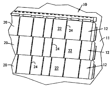
position. Also, this problem is exacerbated by the need for such panels to
overlap in order
to conceal their attachment points because connections are hidden from the
installer as
- r , . .p ~ ~.w~.u.,. .....1.. i~.l...,.". ,1 ~~
CA 02551892 2006-07-13
they are attached during installation. The installer is often forced to either
position his
head in an awkward viewing position near the wall surface when fitting the
panel into
position.
[0005] Further, prior panels have employed fastener attachments located on the
rear of the panels that have no relations to reference elements on the front
side of the
panel. For example, one prior design comprises a series of tabs at intervals
on the rear
side of the panels that do not correspond to arrangements of any elements or
reference
points on the front side. This problem hampers installation because as
described above,
these elements are hidden from the installer during installation and the
installer cannot, by
simply looking at the front of the panel, identify the locations of the
attachment elements
on the rear side of the panel.
[000b] Prior known panel designs have also employed connections that lock
firmly
into place upon attachment. The problem with such a connection is that it may
be so rigid
that it cannot accommodate the inevitable movement associated with thermal
expansion or
contraction or the settling of the underlying wall surface after the panels
are installed.
This may cause buckling of the paneling or tearing of the attachments.
[0007] Also, many prior panel designs have been difficult to cut, trim, or
otherwise
adjust to fit into tight areas along the wall surface, such as within the
gable of the roofline
or the area surrounding windows or other surface irregularities. Some existing
panels may
only be cut in certain structurally designated locations without comprising
their overall
structural integrity. Other panels are made of materials that are difficult to
cut
occasionally requiring certain types of saws and saw blades.
[0008] In addition, many installers prefer panels that are well over the 8-
foot
length such as is common with aluminum siding or extruded vinyl siding.
However, the
extrusion process is not capable of providing a decorative appearance on the
face of a
siding panel that has the detail that can be obtained by using a process such
as the injection
molding process. For example, the extrusion process is not suitable for
forming a panel
having simulated cedar. shake elements. The best process for forming elements
of this
type is the injection molding process; however, due to the cost of providing
dies and
extension machines of sufficient size, it is not common to use the injection
molding
process to produce panels that are 8 feet or longer. The vacuum thermal
process has also
been used to provide a simulated shake element on polymer panels in longer
lengths;
-2-
CA 02551892 2006-07-13
however, the aesthetic appearance and detail of panels formed with this
process is
considerably lacking compared to panels formed by the injection molding
process.
[0009] It is therefore an object of the present invention to provide a wall
panel that
is easy to install. It is a further object that the invention that the panel
have sound
connections, but will readily allow for expansion and contraction of panels
without
comprising the integrity of the connections or adversely affecting the panels.
It is also an
object of the invention that the panels may be readily installed by a single
installer.
Another object of the invention is to provide a siding panel that may be
formed by the
injection molding process to obtain the superior aesthetics of simulated
building elemerns
such as cedar shake and that can be produced in lengths of 8 feet or longer.
[00010] One method of joining panels of a shorter lengths to form panels of a
longer length by using a splicing member is disclosed in U.S. Patent Nos.
6,OS0, 041 and
6,393,792 Bl, both to Mowery et al, and both of which are incorporated in
their entirety
herein by reference. Mowery, et al, discloses a splicing member having a
formed flange
that is received in a protruding flange of the panel. The splicing member may
be attached
to the panels using a fastener such as a rivet or screw, by use of an
adhesive, or by welding
the splicing member to the panels. It would be desirable, however, to provide
a simple
splicing member that can be used to join two sections of panel members
together and that
does not require locking flanges.
[00011] As such, an additional object of the invention is to provide a panel
that has
two or more sections joined together using a splicing member that does not
require a
flange or other interlocking configuration that fits into the flange portion
of the panels
therein.
[00012] A further object of the invention is to provide a method for cutting
panels
that are fused together io minimize waste. These and other objects of the
invention have
been accomplished by the decorative wall panels as set forth and described
below.
SUMMARY OF THE 1NVENT1ON
[00013] It is a feature of the invention to provide a polymer siding panel for
mounting on a wall surface that in one embodiment includes at least two
horizontal
adjacent sections; a plurality of decorative elements integrally formed with
the panel and
-3-
CA 02551892 2006-07-13
disposed in at least one row, the decorative elements defining a front face of
the siding
panel; a top edge disposed above the decorative elements; a plurality of
apertures formed
in and extending through the siding panel disposed below the top edge and
above the
decorative elements; a plurality of downwardly depending tabs located on the
front face of
the siding panel; an upwardly facing channel formed on a rear side of the
siding panel
opposite the front face; and at least two splicing members.
[00014] The splicing members may be transparent or translucent and
manufactured
from a polymer that is different than the polymer of the siding panel, and one
of the
splicing members may be welded to and joining the sections to one another.
[00015] The other splicing member can be welded to one of the sections at a
side
edge opposite the side edge adjoining the other section. The other splicing
member may
extend beyond she respective side edge. The upwardly facing channel may have a
vertical
leg and a bottom leg, and one of the side edges of the parcel can include a
notch in the
vertical leg. The polymer siding panel may further include an upwardly
extending lip on
the bottom leg adjacent the notch. The bottom leg may have a portion adjacent
the notch
that is stepped to be higher than the rest of the bottom leg. The upwardly
extending lip
can be positioned intermediate the rear face and an outer end of the bottom
leg. The side
edge opposite the side edge having the notch may include a horizontal slot in
the vertical
leg. The slot can be configured to receive the stepped portion of the bottom
leg of an
adjacent panel with the upwardly extending lip on the adjacent panel fitting
behind the
vertical leg above the horizontal slot.
[00016] The polymer siding panel may also include scrap reducing cutting
planes
for trimming or cutting the length of the panel to reduce waste. The vertical
leg of the
upwardly extending channel may include a horizontal slot coinciding with each
of the
cutting planes.
[00017] The upwardly facing channel may include a vertical leg having a
projection
extending back therefrom away from the rear face. The front face of the panel
may
include a groove above the decorative elements configured to receive the
projection of a
vertically adjacent panel. The groove can lock with the projection of the
vertically
adjacent panel to prevent relative vertical movement between the panels while
allowing
the panels to slide horizontally relative to one another.
-4-
n r ~..! i i.wn",r.. i .-,1 .e n..imn.-a -.1-,i
CA 02551892 2006-07-13
[00018] It is also a feature of the invention to provide an embodiment of a
polymer
siding panel for mounting on a wall surface that includes a plurality of
decorative elements
integrally formed with the panel and disposed in at Ieast one row, the
decorative elements
defining a front face of the siding panel; a top edge disposed above the
decorative
elements; a plurality of apertures formed in and extending through the siding
panel
disposed below the top edge and above the decorative elements; a bottom end; a
plurality
of downwardly depending tabs located on the front face of the siding panel; an
upwardly
facing channel formed on a rear side of the siding panel along the bottom end,
the channel
having a vertical leg and a bottom leg and the channel configured for receipt
of the tabs of
a vertically adjacent panel; and a pair of side edges, one of the side edges
including a
notch in the vertical leg of the upwardly facing channel and an upwardly
extending lip on
the bottom leg adjacent the notch. The bottom leg may have a stepped portion
adjacent
the notch that is vertically offset from this remainder of the bottom leg.
j00019] The upwardly extending lip can be located intermediate the rear face
and an
outer end of the bottom leg. The side edge opposite the side edge with the
notch may
include a horizontal slot in the vertical Ieg. The horizontal slot may be
configured to
receive the stepped portion of the bottom leg on an adjacent panel with the
upwardly
extending lip located behind the vertical leg above the horizontal slot.
(00020] The polymer siding panel may further include at least two horizontal
adjacent sections and at least two splicing members. The splicing members can
be
manufactured from a polymer, and one of the splicing members can be welded to
and join
the sections to one another along side edges thereof. The other splicing
member can be
welded to one of the sections at a side edge opposite the side edge joined to
the other
section, with the other splicing member extending beyond the respective side
edge.
[00021 ] The polymer siding panel may further include scrap reducing cutting
planes
to trim or cut the panel to reduce waste. The vertical leg of the upwardly
facing channel
may include a horizontal slot coinciding with each of the cutting planes.
[00022) The polymer siding panel may further include a projection extending
back
from the vertical leg of said upwardly facing channel away from the rear face
and a groove
above the elements configured to receive the projection of a vertically
adjacent panel. The .
groove may lock with the projection of the vertically adjacent panel to
prevent relative
-5-
. ...E i ~"~n"~.....,yn, ~..~..."....,..~
CA 02551892 2006-07-13
vertical movement between the panels while allowing the panels to slide
horizontally
relative to one another.
[00023) It is another feature of the invention to provide an embodiment of a
polymer siding panel for mounting on a wall surface that includes a plurality
of decorative
elements integrally formed with the panel and disposed in at least one row,
the decorative
elements defining a front face of the siding panel; a top edge disposed above
the
decorative elements; a plurality of apertures formed in and extending through
the siding
panel disposed below the top edge and above the decorative elements; a bottom
end; a
plurality of downwardly depending tabs located on the front face of the siding
panel; an
upwardly facing channel formed on a rear side of the siding panel at the
bottom end, the
channel including a vertical leg and a bottom leg, and the channel configured
for receipt of
the tabs of an adjacent panel; and scrap reducing cutting planes for trimming
or cutting the
panel to reduce waste. The vertical leg of the upwardly facing channel may
include a
horizontal slot coinciding with each of the cutting planes.
[00024] The polymer siding panel may further include at least two horizontal
adjacent sections and at least two splicing members. The splicing members can
be
translucent and manufactured from a different polymer than the panel, and one
of the
splicing members can be welded to and join respective side edges of the
sections to one
another. The other splicing member can be welded to one of the sections at a
side edge
opposite the side edge joined to the other section, with the other splicing
member
extending beyond the respective side edge. One side edge of the panel may
include a
notch in the vertical leg and an upwardly extending lip on the bottom leg
adjacent the
notch. 'The bottom leg may have a stepped portion adjacent the notch. The side
edge
opposite the side edge with the notch has a horizontal slot in the vertical
leg. The
horizontal slot can be configured to receive the stepped portion of the bottom
leg on an
adjacent panel with the upwardly extending lip located behind the vertical leg
above the
horizontal slot of the adjacent panel. The side edges of the adjoining
sections may have
the same mating conf guration as the side edges of the panel.
[00025] The polymer siding panel may further include at least one projection
on the
vertical leg of the upwardly facing channel extending back away from the rear
face and a
groove in the front.face above the elements configured to receive the
projection of a
_6_
.. . , ",."..,. . . ,, .. , , .. , ., .,
, ~. ...La,a"~~....,I" m,..i.~ ~rv r .I. "
CA 02551892 2006-07-13
vertically adjacent panel. The groove can lock with the projection of the
vertically
adjacent panel to prevent relative vertical movement between the panels while
allowing
the panels to slide horizontally relative to one another.
[00026) It is yet another feature of the invention to provide an embodiment of
a wall
covering that includes a plurality of polymer siding panels for mounting on a
wall surface
wherein a plurality of decorative elements are integrally formed on each panel
and
disposed in at least one row, the decorative elements defining a front face of
the siding
panels; a top edge on each panel disposed above the decorative elements; a
plurality of
apertures formed in and extending through each of the siding panels below the
top edge
and above the decorative elements; a bottom end on each panel; a plurality of
downwardly
depending tabs located on the front faces of the siding panels; and an
upwardly facing
channel formed on a rear side of each siding panel, the upwardly facing
channels including
a vertical leg and a bottom leg and configured for receipt of the tabs of a
vertically
adjacent panel so that each of the vertical legs includes at least one
projection extending
back from the rear side of the panels and each front face includes a groove
therein above
said elements. 'The grooves are configured to receive the projection of a
vertically
adjacent panel.
[00027) Each of the panels may include at least two horizontally adjacent
sections
and two splicing members. The splicing members may be translucent and
manufactured
from a transparent or translucent polymer, and one of the splicing members may
be
welded to adjoining sections of a panel to join respective side edges thereof.
[00028) Each panel may include a pair of side edges and a notch adjacent one
side
edge in the vertical leg of the upwardly facing channel and an upwardly
extending lip on
the bottom leg adjacent the notch. The bottom leg may have a stepped portion
adjacent
the notch: The side edge of each panel opposite the side edge with the notch
may have a
horizontal slot in the vertical leg. The horizontal slot can be conf gured to
receive the
stepped portion of the bottom leg ort an adjacent panel with the upwardly
extending lip on
the adjacent panel located behind the vertical leg above the horizontal slot.
[00029) Each of the panels may also include scrap reducing cutting planes for
trimming or cutting the panels to reduce waste. 'The vertical legs of the
upwardly facing
n r. .4w ..~,.nl",.~.. ..M.wnml..w.r .n ii
CA 02551892 2006-07-13
channel on each of the panels may include a horizontal slot coinciding with
each of the
cutting planes.
[00030] 'The grooves may lock with the projection of a vertically adjacent
panel to
prevent relative vertical movement between the panels while allowing the
locked panels to
slide horizontally relative to one another.
BRIEF DESCRIPTION OF THE DRAWINGS
[00031) The above-mentioned and ocher features and objects of this invention
and
the manner of obtaining them will become more apparent and the invention
itself will be
better understood by reference to the following description of embodiments of
the present
invention taken in conjunction with the accompanying drawings, wherein:
[00032) Figure 1 is a perspective view of a face side of a plurality of the
panels of
the present invention as would appear mounted on a wall surface;
[00033] Figure 2 is a perspective view of the rear side of the plurality of
the panels
of Figure 1;
[00034] Figure 3 is a perspective view of the face side of a single row panel
of the
present. invention having a spliced connection and removed from the wall
surface;
[00035] Figure 4 is a perspective view of a side connection on one end of a
panel
having a receiving slot therein;
[00036) Figure 5 is a perspective view of the other end of the panel of Figure
4
showing the mating side connection;
[00037] Figure 6 is a front perspective view showing a connection between two
bonded sections of a panel or the connection of two adjacent panels as
installed;
[00038] Figure 7 is a rear perspective view showing the joint of Figure G
including a
splicing member;
[00039] Figure 8 is a front perspective view of two horizontally adjacent
panels
being joined together;
[00040] Figure 9 is a rear perspective view of two horizontally adjacent
panels
being joined together;
_g_
o..,b,,J."em. J,ul,.,lau..e,bi
CA 02551892 2006-07-13
[00041) Figure 10 is an enlarged perspective view of the bottom connection of
two
adjoining panels to be connected;
[00042] Figure I 1 is a rear enlarged perspective view of the bottom section
of the
two adjoining panels of Figure 10 with the panels partially connected
together;
/00043] Figure 12 is a side view of one panel of the present invention;
[00044] Figure 13 is a side view of two vertically adjacent panels of the
present
invention connected together;
[00045] Figure i 3A is an enlargement of the area indicated in Figure 13 of
two
vertically adjacent panels connected together;
[00046] Figure 14 is a front plan view of a panel of the present invention
showing
scrap reducing cutting planes;
[00047] Figure 15 is a rear plan view of a panel of Figure 14 showing the
cutting
planes; and
[00048] Figure 16 is a front perspective view of panels that have been cut
along the
different cutting planes of Figure 14.
[00040 Corresponding reference characters indicate corresponding pans
throughout the several views. Although the drawings represent embodiments of
the
present invention, the drawings are not necessarily to scale and certain
features may be
exaggerated in order to better illustrate and explain the present ~ invention.
The
exemplification set out herein illustrates embodiments of the invention, and
such
exemplifications are not to be construed as limiting the scope of the
invention in any
manner.
DETAILED DESCRIPTION OF EMBODIMENTS OF THE INVENTION
[00050] For the purposes' of promoting an understanding of the principles of
the
invention, reference will now be made to the embodiments illustrated in the
drawings,
which are described below. It will nevertheless be understood chat no
limitation of the
scope of the invention is thereby intended. The invention includes any
alterations and
further modifications in the illustrated devices and described methods and
further
-9-
:. ~ ,I i.*"vr,.v::. r.r~,rr I.,Aa..nr ~,
CA 02551892 2006-07-13
applications of the principles of the invention, which would normally occur to
one skilled
in the art to which the invention relates.
[00051] The present invention provides exterior siding panels preferably
formed by
an injection molding process that is designed to facilitate easy installation
and dependable
performance. Referring. to Figures 1 and 2, front and rear respective views
are shown of a
wall covering generally indicated as 10. Wall covering 10 is mounted on a wall
surface
11, as shown in Figure 1. The depiction in Figure I shows three rows of siding
panels,
generally indicated as 12 fitted vertically together.
[00052) Referring to Figures 3-6, one of the siding panels 12 is shown apart
from
the other panels. Each siding panel 12 includes a top portion generally
indicated as 13, a
bottom portion generally indicated as 14, a right-side portion generally
indicated as 16,
and a left-side portion generally indicated as 18. In the embodiment shown,
panels 10 also
include a front face 20 having decorative elements 22, which are separated by
gaps 24, to
form a single horizontal row of decorative elements 22 having the appearance
of cedar
shake siding shingles. The decorative elements 22 and panels 12 may have
varied widths
to provide a more natural appearance.
[00053] As best shown in Figures 4 and S, right-side portion 16 includes a
side edge
28, and left-side portion 18 includes a side edge 30. The top portion 13 of
each panel 12
has a top edge 32, while the bottom portion 14 includes a bottom edge 34.
Referring now
to Figures 2, 4, and 5, panels 12 also include a rear side 36 having a
plurality of vertically
oriented reinforcing ribs 38. Reinforcing ribs 38 coincide with gaps 24 formed
between
decorative elements 22. Extending through panels 12 are a plurality of nail-
mounting
apertures 40 disposed in a generally horizontal row adjacent top edge 32. In
the
embodiment shown, the mounting apertures 40 are elongated to accommodate
thermal
expansion and contraction of the panels. Panels 12 also include support ridges
46 located
on either side of nailing apertures 40 extending in a generally horizontal
direction across
rear side 36 to side portions 16, 18 for supporting the panels against wall
swface 1 I when
mounted thereto.
(00054) In the embodiment shown, panels 12 each include two or more sections
generally indicated as 47 that are preassembled and connected to one another
at a joint 48
prior to mounting panel 12 to wall surface 11. Panels I2 include a number of
features for
interconnecting sections 47 together and for also interconnecting horizontally
and
-10-
,. ,. *r .r.,r.,. :.r,:.,:,y"w,.:,.,r
.., r .-..4i ~.W .M,. m.W .~-1,.-iar.nw.r...k-a
CA 02551892 2006-07-13
vertically adjacent panels 12 to one another when installing them on the wall
surface 11.
For connecting 'one panel above another, each panel includes a plurality of
downwardly
depending tabs 49 extending from front face 20. As best shown in Figures 12,
13, and
13A, each downwardly depending tab 49 has a base 49a in a vertical leg 49b.
Tabs 49 are
located in an intermittent horizontal row below nailing apertures 44 and above
decorative
elements 22. Also located on front face 20 of siding panels 12 is a
horizontally extending
groove 50 that is located above decorative elements 20 behind or near the
bottom of
vertical legs 49b of downwardly depending tabs 49 for reasons discussed below.
[00055] Panels I2 also include an upwardly facing channel 51 formed along the
bottom edge 34 on rear side 36. In the embodiment shown, inwardly facing
channels 51
each include a rearwardly projecting leg 54, and an upwardly extending leg 56,
having an
upper beveled end 58. Also located on upwardly extending leg 56 are
intermittently
spaced projections 60 extending away from rear side 36. Projections 60 run in
a
horizontal direction and are configured to be received by the horizontal
groove SO of a
vertically adjacent panel 12. Although projections 60 are shown in an
intermittent
arrangement, it should be appreciated that continuous projections could be
used that
extend across the length of the panel.
X00056) Referring again to Figures 4 and 5, to connect side-by-side panels 12
and
panel sections 47 to one another, the right-side portion 16 includes a tongue
64, which
includes an upper portion 66a and a lower portion 66b. 1n the embodiment
shown, upper
portion 6ba includes a hole 67 for receipt of a nail (rot shown) for centering
the panels. A
slot 68 separates upper portion 66a and Iawer portion 66b. At the lower end of
right-side
portion 16, a notch generally indicated as 69 is located in upwardly extending
leg 56 of
upwardly facing channel SI. Furthermore, rearward projecting leg 54 of
upwardly facing
channel 51 has a stepped portion generally indicated as 70 at the right-side
portion 16.
Atso located on rearwardly projecting leg 54 in the region of stepped portion
70 is an
upwardly extending lip 71, which is slightly offset from upwardly extending
leg 56 and
located closer to rear side 36 of panel 12. Located on the rear side of lower
portion 66b of
tongue. 66 is a vertically extending opening 72. Ope~~ing 72 may also be a
groove into
tongue 64 and may be intermittent or longer or shorter than shown. A nailing
aperture 73
may be located on the upper portion 66a of tongue 64. Channel 51 may also
include a
plurality of weep holes (not shown) located at the bottom of upwardly
extending leg 56 for
allowing any moisture trapped in channel S 1 to drain therefrom.
_11_
..-.~~ ,.*"w.,. ....,~.,w~",,.~......,~~
CA 02551892 2006-07-13
[00057] At the left-side portion I 8 of panels 12 and panel sections 47, a
horizontal
slot generally indicated as 74 is provided in upwardly extending leg 56 of
upwardly facing
channel 51, as best shown in Figure 4. For reasons discussed below, horizontal
slot 74 is
configured to receive stepped portion 70 of an adjacent panel 12 or panel
section 47. Lefl-
side portion 18 also includes a protrusion 76 that is aligned with and
receivable by slot 68
of an adjacent panel 12 or panel section 47. Left side 18 may also include a
nailing
aperture 77a and a slot opening 77b that aligns with hole 67 for receipt of
the centering
nail ('not shown). 1t should also be appreciated that when panel sections 47
are joined
together, apertwe 73 and 77a will be aligned with one another and overlap.
[00058] Referring now to Figwes 2 and 7, splicing members 80 are provided for
joining two horizontally adjacent panels 12 or two panel sections 47. In the
embodiment
shown, splicing members 80 are rectangular panels and may be made from a
transparent or
translucent polymer such as polypropylene for reasons discussed below. 'The
splicing
member may also be opaque and match the color of the panels if a suitable weld
can be
produced. Splicing member 80 may also include a lip or ridge configwed to be
received
in opening 72 for providing a more secwe joint.
[000591 Now referring to Figures I4-16, panels 12 may also include marked
cutting
planes 82 that may be used for reducing scrap when trimming or cutting panels
12. As
shown in Figure 15, aligned with the cutting planes, horizontal slots 84 may
also be
included in upwardly extending leg 56, which will resemble horizontal slot 74
when
panels 12 are cut along the respective cutting plane 82. Cutting the panels
along one of
the respective cutting planes produces the reduced length panels generally
indicated as
I 2a-12c in Figure I b. It should be appreciated that horizontal slots 74 and
84 may also
function as weep holes. Furthermore, in the embodiment shown in Figures 14-16,
three
cutting planes are shown on one of the panel sections 47; however, it should
be realized
that the number and placement of the cutting planes may be varied as desired.
[00060) As discussed above, one method of providing a desirable appearance on
panel 12, which may be made from a polypropylene, vinyl, or other polymer
material, is
the injection molding process; however, the length of the panels foamed by
this method
may be limited due to the cost of providing dies and injection molding
machines of
sufficient size to make panels that are 8 feet or longer. Accordingly, in one
embodiment
of the invention, panel sections 47 are provided, which may be spliced
together to provide
-12-
" .. , ~.. ~""" , ..., ,. ,."...... ., .~
.......4 i ..4wlwH... "..r/~v Lnda...a..p .4-ii
CA 02551892 2006-07-13
longer panels 12. To splice panel sections 47 together, the ends of each panel
section are
provided with the end connections shown in Figures 4 and 5 on right-side
portion Ib and
left-side portion 18. As shown in Figures 7 and 9-I 1, the panel sections are
connected so
that stepped portion 70 on one section 47 is received in the horizontal slot
74 of the
horizontally adjacent section 47 with upwardly extending lip ?I located behind
the
upwardly extending leg 56 of the left-side portion 18 on the adjacent section
47.
Furthermore, protrusion 76 of the adjacent section 47 is received in slot 68
of the one
section 47 between upper portion 66a and lower portion 66b of tongue 64. In
addition, to
secure the panel sections together, a splicing member 80 may be used at each
connection.
The splicing member may be adhered to the rear sides 36 of panel sections 47
adjacent
respective right-side and left-side portions 16, 18 by use of an adhesive, by
welding or
using other known bonding means. Use of laser welding, as is known, may be
preferable
for minimizing heat input and distortion of the welding process. Furthermore,
if.splicing
members 80 are transparent or translucent, this facilitates passing the laser
through the
splicing member to the opaque panel surface, where it will heal the members up
and form
a lap weld joint between the panel sections and splicing member. It should be
appreciated
that the material used to make splicing members 80 may be different than the
panels, but
should have a coefficient of thermal expansion chat is compatible with the
material used to
make panels 12 so that the panels or joints will not buckle or tear the welds
during
expansion and contraction of the panels due to changes in temperature.
[00061] To assemble panels 12 on a wall, a first horizontal row is provided.
Horizontally adjacent panels 12 are connected to one another the same as panel
sections
47 except that splicing member 80 is only welded or otherwise attached to only
one of
either right- or left-side portions 16 or 18; the splicing member merely
overlaps the other
adjoining side to provide support at the connection. It should be appreciated
that ridges 72
may be used on either right- or left-side portion 16 or 18 to provide a
separation of the
splicing members 80 from the rear side 36 for ease in fitting the panels
together. The
panels are attached to wall surface I 1 using nails or other fasteners (not
shown) as is well
known, inserted through mounting apertures 40, 73 and 77a, 77b.
[00062] To install a second and subsequent row of panels 12, the upwardly
extending leg 56 of upwardly facing channel 51 on the upper panel 12 is
inserted into the
space behind leg 49b of downwardly depending tabs 49 on the lower panels 12.
When
inserted thusly, the projections 60 on the upwardly extending leg 56 of the
upper panel
-13-
u-.,4~ r.r~.a..,.,.. r...,l~n~.v"y........~E..i
CA 02551892 2006-07-13
will be interlocked with horizontal groove 50 of the lower panel. ?his will
hold the upper
panel to the lower panel until it is nailed to wall surface 11; however, the
projection can
slide along the groove to allow horizontal movement of the upper panel
relative to the
lower panel so that it can be slid into place.
[00063] For staggering the decorative elements 22 on the panels and when a
full
length panel is not required, the panels may be cut along a desired cutting
plane 82. When
cut along the cutting planes, a horizontal slot 84 will now be located along
the left-side
portian t 8 of the cut panel, which may be installed to any right-side portion
16, as
horizontal slots 84 can receive the stepped portion 70 of the adjacent panel
the same as
horizontal slot 74.
/00064] While the invention has been taught with specific reference to these
embodiments, one skilled in the art will recognize that changes can be made in
forth and
detail without departing from the spirit and scope of the invention. The
described
embodiments are to be considered, therefore, in all respects only as
illustrative and not
restrictive. As such, the scope of the invention is indicated by the following
claims rather
than by the description.
-14-