Language selection

Search

Patent 2552065 Summary

Third-party information liability

Some of the information on this Web page has been provided by external sources. The Government of Canada is not responsible for the accuracy, reliability or currency of the information supplied by external sources. Users wishing to rely upon this information should consult directly with the source of the information. Content provided by external sources is not subject to official languages, privacy and accessibility requirements.

Claims and Abstract availability

Any discrepancies in the text and image of the Claims and Abstract are due to differing posting times. Text of the Claims and Abstract are posted:

  • At the time the application is open to public inspection;
  • At the time of issue of the patent (grant).
(12) Patent Application: (11) CA 2552065
(54) English Title: WEAR PAD ENDLESS BELT CONVEYOR SLIDE
(54) French Title: RAMPE DE TRANSPORTEUR A COURROIE SANS FIN ET PATIN D'USURE
Status: Deemed Abandoned and Beyond the Period of Reinstatement - Pending Response to Notice of Disregarded Communication
Bibliographic Data
Abstracts

English Abstract


A wear pad for use on a slide of an endless track conveyor belt is
mounted on a base extending transversely beneath the belt for supporting the
latter. The top surface of the wear pad includes a plurality of transversely
extending grooves or channels in the top surface thereof for discharging
liquid
failing onto the wear pad from the belt whereby drag on the belt by the liquid
is
substantially reduced.


Claims

Note: Claims are shown in the official language in which they were submitted.

CLAIMS
1. A wear pad for use on a slide of an endless track conveyor belt comprising
an elongated body having a flat top surface for slidably supporting a conveyor
belt during travel of the belt over the top surface between leading and
trailing
edges of the top surface; and a plurality of grooves in said top surface
extending
between the leading and trailing edges of the body for discharging liquid
falling
onto the top surface, whereby drag between the wear pad and the belt is
reduced.
2. The wear pad of claim 1, wherein said leading and trailing edges of said
body are beveled, and said grooves extend between said beveled edges.
3. The wear pad of claim 2, wherein said grooves are parallel and spaced
apart by a distance greater than their width.
4. The wear pad of claim 3, wherein said grooves have square cross
sections.
6

Description

Note: Descriptions are shown in the official language in which they were submitted.


CA 02552065 2006-07-14
WEAR PAD FOR ENDLESS BELT CONVEYOR SLIDE
BACKGROUND OF THE INVENTION
FIELD OF THE INVENTION
This invention relates to a wear pad for use on a slide of an endless belt
conveyor.
DISCUSSION OF THE PRIOR ART
Slides, which have been referred to as idlers have been used for some
time to support conveyor belts. For example, United States Patent No.
6,854,593 issued to Boudreau et al on February 15, 2005, discloses a slide
referred to therein as a pad-type idler, for slidably supporting a continuous
conveyor belt. The pad-type idlers are supported on a metal support above a
base. When conveying a liquid-containing substance, e.g. in the food
processing
industry, liquid falls onto the slides where it accumulates. The presence of a
liquid between the belt and the slides results in drag (skin friction drag)
between
the belt and the slides which causes the belt to slow down or stop.
GENERAL DESCRIPTION OF THE INVENTION
The object of the present invention is to provide a solution to the above
identified problem in the form of a relatively simple conveyor slide wear pad,
which reduces or eliminates the accumulation of liquid on the slide, and
consequently drag between the belt and the slide.
Accordinoly, the invention relates to a wear pad for use on a slide of an
endless track conveyor belt comprising an elongated body having a flat top
surface for slidably supporting a conveyor belt during travel of the belt over
the
1
I ,... ~

, . . ..,.w., 1 ..,,.. . I...:..i,.m,..l
CA 02552065 2006-07-14
top surface between leading and trailing edges of the top surface; and a
plurality
of grooves in said top surface extending between the leading and trailing
edges
of the body for discharging liquid falling onto the top surface, whereby drag
between the wear pad and the belt is reduced.
BRIEF DESCRIPTION OF THE DRAWINGS
The invention is described below in greater detail with reference to the
accompanying drawings, wherein:
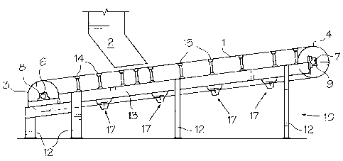
Figure 1 is a schemat'ic side view of an endless belt conveyor of the type
which can employ a wear pad in accordance with the invention;
Figure 2 is a front view of a slide assembly incorporating a wear pad in
accordance with the invention;
Figure 3 is an end view of the wear pad of Fig. 2 mounted on a crossbar of
the slide assembly of Fig. 2;
Figure 4 is a front view of the wear pad and crossbar of Fig. 3;
Figure 5 is a top view of the wear pad of Figs. 3 and 4; and
Figure 6 is a cross section taken generally along line 6-6 of Fig. 5.
DESCRIPTION OF THE PREFERRED EMBODIMENT
Referring to Fig. 1, the wear pad of the present invention is intended for
use in a conveyor assembly of the type including an inclined endless belt for
receiving material to be conveyed from a chute 2 located above the belt. The
belt 1 passes around a tail pulley 3 and a driven head pulley 4. The pulleys 3
and 4 include axles 6 and 7 mounted in pillow block bearings 8 and 9,
respectively. The bearings 8 and 9 are mounted on the ends of a frame
2

, . . . , x -1 ...nx..1 x I...d. r,. r ,1. .
CA 02552065 2006-07-14
indicated generally at 10, which includes a plurality of legs 12 and sides 13
(one
shown) supported by the legs.
During travel over the top of the pulleys 3 and 4, the belt 1 is supported by
transition slides 14 and troughing slides 15. When passing beneath the pulleys
3 and 4 the belt is supported by return slides 17. Each of the transition and
troughing slides 14 and 15 includes a frame defined by a tubular base 18 with
plates 19 on the ends thereof for mounting the assembly on the main frame 10
of
the conveyor. The top ends of vertical center posts 21 extending upwardly from
the middle of the base 18 are interconnected by a crossbar 22.
A wear pad 24 in accordance with the present invention is mounted on the
crossbar 22. Inclined wear pads 25 are mounted on arms 26 connected to and
extending outwardly and upwardly from the ends of the crossbar 22. Inclined
side posts 28 extend between the base 18 and the arms 26 for supporting the
latter. The basic difference between the transition and troughing slide
assemblies 14 and 15 is the angle of the inclined wear pads 25 with respect to
the horizontal. The troughing wear pads and the supporting arms 26 have a
greater inclination for forming a deep material conveying trough. The wear
pads
24 and 25, which are formed of a Teflon (trade-mark for
polytetrafluoroethylene)
composite, are similar to the pads disclosed by US Patent No. 6,854,592,
issued
February 15, 2005.
The pad 24 can optionally include cylindrical or frusto-conical wear
indicators of the types described in applicant's Canadian Patent Application
3

. .. ... ............ k ,..xn.r.. . .rlNl.r-In.m.. I-r
CA 02552065 2006-07-14
2,327,646 and United States Patent No. 6,854,593, respectively and which are
incorporated herein by reference.
Referring to Figs. 2 to 6, the wear pad 24 in accordance with the present
invention is basically an elongated rectangular parallelepipedic body with a
flat,
rectangular bottom surface 29 and a flat rectangular top surface 30 over which
the belt 1 slides. The top of the front and rear ends 31 (the leading and
trailing
ends in the direction of belt travel) of the pad 24 are beveled. Holes 32 in
the
pad 24 receive bolts 33 for mounting the pad on the crossbar 22. The pad is
spaced apart from the crossbar 22 by a pair of spacers 35. The bolts 33 extend
through the spacers 35 and the crossbar 22. Nuts 36 are threaded onto the
bottom ends of the bolts 33 beneath the crossbar 22.
As mentioned above, when conveying liquid-containing material, e.g. in
the food processing industry, liquid tends to accumulate on the wear pads 24.
The liquid literally sucks the belt 1 against the pads 24 which can slow down
or
stop the belt. Drag on the belt by the liquid is reduced by providing a
plurality of
grooves or channels 38 extending between the leading and trailing edges (in
the
direction of belt travel) in the top of each pad 24. Liquid landing on the
pads 24
is discharged via the grooves 38. While the dimensions of the pad 24 and the
grooves 38 are not critical, in a thirty inch long pad, three 0.25 by 0.25
inch
grooves 38 spaced slightly over an inch apart in the center of the pad are
effective. Of course, additional grooves with different dimensions can be used
in
the top of the pad 24.
4
-110541s vI
, , .. , ,.. . , , ... ,r..,. .I,

. . ....h.l =..wx..... ..I a...1..,.....L..
CA 02552065 2006-07-14
The wear pad 24 can also be mounted on the arms 26 in place of the wear
pads 25.
It will be appreciated that while the wear pad of the present invention has
been described in a particular environment, i.e. on a specific slide assembly,
the
wear pad can be used on different endless belt conveyor slides. Moreover, the
number of grooves and the dimensions thereof can vary depending upon, inter
alia, the belt width and the speed of belt travel over the pads.
5
41054480
. . . .. .. . ... ......., . .,......._. ..'... i

Representative Drawing
A single figure which represents the drawing illustrating the invention.
Administrative Status

2024-08-01:As part of the Next Generation Patents (NGP) transition, the Canadian Patents Database (CPD) now contains a more detailed Event History, which replicates the Event Log of our new back-office solution.

Please note that "Inactive:" events refers to events no longer in use in our new back-office solution.

For a clearer understanding of the status of the application/patent presented on this page, the site Disclaimer , as well as the definitions for Patent , Event History , Maintenance Fee  and Payment History  should be consulted.

Event History

Description Date
Inactive: Office letter 2011-07-27
Revocation of Agent Requirements Determined Compliant 2011-07-27
Appointment of Agent Requirements Determined Compliant 2011-07-27
Appointment of Agent Request 2011-07-15
Revocation of Agent Request 2011-07-15
Application Not Reinstated by Deadline 2011-07-14
Time Limit for Reversal Expired 2011-07-14
Deemed Abandoned - Failure to Respond to Maintenance Fee Notice 2010-07-14
Amendment Received - Voluntary Amendment 2009-11-12
Application Published (Open to Public Inspection) 2008-01-14
Inactive: Cover page published 2008-01-13
Letter Sent 2007-09-18
Inactive: Single transfer 2007-07-13
Inactive: First IPC assigned 2007-03-06
Inactive: IPC assigned 2007-03-06
Inactive: Courtesy letter - Evidence 2006-08-15
Application Received - Regular National 2006-08-10
Filing Requirements Determined Compliant 2006-08-10
Inactive: Filing certificate - No RFE (English) 2006-08-10
Small Entity Declaration Determined Compliant 2006-07-14

Abandonment History

Abandonment Date Reason Reinstatement Date
2010-07-14

Maintenance Fee

The last payment was received on 2009-07-13

Note : If the full payment has not been received on or before the date indicated, a further fee may be required which may be one of the following

  • the reinstatement fee;
  • the late payment fee; or
  • additional fee to reverse deemed expiry.

Please refer to the CIPO Patent Fees web page to see all current fee amounts.

Fee History

Fee Type Anniversary Year Due Date Paid Date
Application fee - small 2006-07-14
Registration of a document 2007-07-13
MF (application, 2nd anniv.) - small 02 2008-07-14 2008-06-23
MF (application, 3rd anniv.) - small 03 2009-07-14 2009-07-13
Owners on Record

Note: Records showing the ownership history in alphabetical order.

Current Owners on Record
CANGLIDE INC.
Past Owners on Record
JEAN-MARC BOUDREAU
Past Owners that do not appear in the "Owners on Record" listing will appear in other documentation within the application.
Documents

To view selected files, please enter reCAPTCHA code :


To view images, click a link in the Document Description column. To download the documents, select one or more checkboxes in the first column and then click the "Download Selected in PDF format (Zip Archive)" or the "Download Selected as Single PDF" button.

List of published and non-published patent-specific documents on the CPD .

If you have any difficulty accessing content, you can call the Client Service Centre at 1-866-997-1936 or send them an e-mail at CIPO Client Service Centre.


Document
Description 
Date
(yyyy-mm-dd) 
Number of pages   Size of Image (KB) 
Abstract 2006-07-14 1 11
Description 2006-07-14 5 160
Claims 2006-07-14 1 21
Drawings 2006-07-14 3 45
Representative drawing 2007-12-19 1 10
Cover Page 2008-01-04 1 33
Filing Certificate (English) 2006-08-10 1 158
Courtesy - Certificate of registration (related document(s)) 2007-09-18 1 129
Reminder of maintenance fee due 2008-03-17 1 113
Courtesy - Abandonment Letter (Maintenance Fee) 2010-09-08 1 174
Reminder - Request for Examination 2011-03-15 1 126
Correspondence 2006-08-10 1 25
Fees 2008-06-23 1 36
Fees 2009-07-13 1 38
Correspondence 2011-07-15 3 76
Correspondence 2011-07-27 1 13
Correspondence 2011-07-27 1 18