Note: Descriptions are shown in the official language in which they were submitted.
CA 02552345 2006-06-30
WO 2005/069813 PCT/US2005/001052
_1_
FLYING DISC
BACKGROUND OF THE INVENTION
1. Technical Field:
[0001] The present invention relates to flying discs.
2. Description of the Related Art:
[0002] Hand thrown flying toys, and in particular flying discs, continue to be
some of the most
popular recreational toys. Specialty discs having different flight
characteristics, weights, and
materials are now being developed for particular segments of the disc market.
For example,
specialty discs are now being designed and marketed for Ultimate FRISBEE~,
disc golf,
recreational catching, distance throwing, and canine disc sports.
[0003] As set forth in U.S. Patent No. 5,531,624 to Dunipace, disc designs are
commonly
evaluated based upon multiple criteria including: (1) throwability - how
easily the disc is
gripped and released, (2) flight characteristics - flight path, ballistics,
freedom from roll,
resistance to flight path deflection by wind, etc., and (3) durability. Many
disc designs attain
commercially acceptable throwability, flight characteristics, and durability
for their intended use
through the use of high density, semi-rigid materials (e.g., plastics) and low
profiles. A
combination of these features yields discs of acceptable durability that tend
to fly far and fast and
axe at least somewhat resistant to flight path deflection by wind.
[0004] The present inventors recognize, however, that a high velocity, low-
profile flying disc
formed of high density, semi-rigid plastic can be painful and/or difficult to
catch for both
humans and canines. That is, a human user may find that a conventional flying
disc flies to fast
and too far to catch easily, and that when caught, impacts the hand with a
painful sting. In
addition, a dog catching a conventional flying disc formed of semi-rigid
plastic (e.g.,
CA 02552345 2006-06-30
WO 2005/069813 PCT/US2005/001052
-2-
polyethylene or polypropylene) can sustain significant impact on its teeth and
gums, resulting in
bleeding gums and loosened teeth. Moreover, even after short periods of use,
the dog's teeth
may puncture or mar the disc surface, resulting in sharp burs that may further
injure the mouth of
a canine catcher. The flying disc may also travel too far or too fast for a
dog to be able to
successfully catch an acceptably high percentage of throws. The pain, injury
and frustration
attendant to the use of conventional semi-rigid flying discs can thus
discourage their use,
diminishing their recreational utility.
[0005] Despite such drawbacks to the use of high density semi-rigid materials
for flying discs,
particularly for. discs .intended for use by novice users and canines, flying
discs formed of semi-
rigid materials continue to dominate the market because flying discs formed of
more flexible
materials have heretofore exhibited unacceptable flight characteristics and/or
durability.
CA 02552345 2006-06-30
WO 2005/069813 PCT/US2005/001052
-3-
SUMMARY OF THE INVENTION
[0006] In view of the foregoing shortcomings of conventional flying discs, the
present invention
provides an improved flying disc that is suitable for use by novice users or
in canine disc sports.
[0007] According to one embodiment, a flying disc has a radially symmetric
form having an
upper surface and a lower surface. The upper surface includes a raised central
portion, a flat
annular ring encompassing the raised central portion, and a raised rim
extending above and
encompassing the flat annular ring. A maximum height of the central raised
portion above the
flat annular ring is no greater than a height of the raised rim.
[0008] In another embodiment, a flying disc has a radially symmetric form
having an upper
surface and a lower surface. The upper surface includes a raised central
portion, a lower
intermediate surface, and a raised rim extending above and encompassing the
lower intermediate
surface. The raised rim includes a sloped inner sidewall having a flat
profile, a sloped outer
sidewall having a flat profile, and a flat rim top intermediate the sloped
inner sidewall and the
sloped outer sidewall. The sloped inner sidewall has a greatest height at its
outermost extent,
and the sloped outer sidewall has a greatest height at its innermost extent. A
maximum height of
the central raised portion is no greater than a height of the raised rim.
[0009] In still another embodiment, a flying disc includes a radially
symmetric form having an
upper surface and a lower surface, and the upper surface includes a raised
central portion, a
lower intermediate surface, and a raised rim extending above and encompassing
the lower
intermediate surface. The maximum height of the central raised portion is no
greater than a
height of the raised rim. The lower surface has a central generally concave
portion encompassed
by a flat annulax ring corresponding to a location of the lower intermediate
surface on the upper
surface, an annular fillet curve encompassing the flat annular ring, and a rim
foot encompassing
the fillet curve.
CA 02552345 2006-06-30
WO 2005/069813 PCT/US2005/001052
-4-
[0010] All obj ects, features, and advantages of the present invention will
become apparent in the
following detailed written description.
CA 02552345 2006-06-30
WO 2005/069813 PCT/US2005/001052
-5-
BRIEF DESCRIPTION OF THE DRAWINGS
[0011] The novel features believed characteristic of the invention are set
forth in the appended
claims. However, the invention, as well as a preferred mode of use, will best
be understood by
reference to the following detailed description of an illustrative embodiment
when read in
conjunction with the accompanying drawings, wherein:
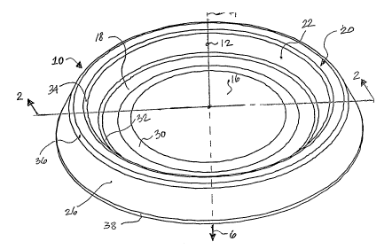
[0012] Figure 1 is an isometric view of an exemplary embodiment of a flying
disc in accordance
with the present invention; and
[0013] Figure 2 is a section view of the flying disc of Figure 1 taken along
the line 2-2.
CA 02552345 2006-06-30
WO 2005/069813 PCT/US2005/001052
-6-
DETAILED DESCRIPTION OF TLLUSTRATIVE EMBODIMENT
[0014] With reference now to the figures, and in particular with reference to
Figure 1, there is
illustrated an isometric view of an exemplary embodiment of a flying disc 10
in accordance with
the present invention. As shown, the exemplary embodiment of flying disc 10 is
radially
symmetric about a central vertical axis 12, and is circular when viewed in
plan along central
vertical axis 12. In the following description and claims, terms such as
"upper" or "above",
"lower" or "beneath", "inward" or "inner", "outer" or "outward" or the like
are employed to
describe flying disc 10. As utilized herein, these terms describe relative
directions when flying
disc 10 is observed in a horizontal, upright orientation such as illustrated
in figures. In other
words, flying disc 10 is described relative to a conventional coordinate
system centered on
central vertical axis 12. As a further clarification, the term "inward" or
"inner" is defined herein
to mean radially toward central vertical axis 12, "outward" or "outer" is
defined herein to mean
radially away from central vertical axis 12, and "upper" and "lower" are
defined herein to mean
axially along central vertical axis 12 in the directions of arrows 4 and 6,
respectively.
[0015] Still referring to Figure 1 and additionally refernng to Figure 2,
which depicts flying
disc 10 in a scaled section taken along line 2 2 of Figure 1, flying disc 10
has an upper surface
14 and a lower surface 40. Upper surface 14 includes a raised central portion
16, which in the
depicted embodiment takes the form of a convex dome; a flat annulax ring 18
encompassing
raised central portion 16; and a raised rim 20 encompassing flat annular ring
18. Raised rim 20
in turn has three principal subsurfaces: an inwardly facing sidewall 22, a rim
top 24, and an
outwardly facing sidewall 26. As best seen in Figure 2, each of surfaces 22,
24, and 26
preferably has a substantially flat profile in section. In addition, the plane
including rim top 24 is
parallel to the plane including flat annular ring 18, both of which are
orthogonal to central
vertical axis 12. It should further be noted that to improve aerodynamics,
each of the principal
subsurfaces of upper surface 14 is joined to an adjacent subsurface by a
respective one of a
number of small interstitial annular curved surfaces 30, 32, 34, 36, and 38.
[0016] As further depicted in Figure Z, lower surface 40 includes four
principal subsurfaces.
CA 02552345 2006-06-30
WO 2005/069813 PCT/US2005/001052
-7-
These subsurfaces include substantially concave central portion 48, a flat
annular ring 46
encompassing raised central portion 48, an annular fillet curve 44
encompassing flat annular ring
46, and rim foot 42. As can be seen by reference to line 52, the depicted
embodiment of
substantially concave central portion 48 includes a convex region 50 to
facilitate release of flying
disc 10 from a mold in which it is formed. Similarly to upper surface 14,
lower surface 40 also
includes a small interstitial annular curved surface 54 joining rim foot 42
and fillet curve 44, and
a small interstitial annular curved surface 56 joining flat annular ring 46
and substantially
concave central portion 48. Flat annular ring 46 and fillet curve 44 directly
abut without any
intermediate surface.
[0017] Flying disc 10 is characterized by excellent throwability. That is,
when gripping and
throwing flying disc 10, the thumb of a human user. naturally rests on rim top
24, and the hand
and fingers curl around outwardly facing sidewall 26 and rim foot 42, causing
the fingertips to
rest against fillet curve 44. When released from this comfortable hand
position, level, stable
flight of flying disc 10 is promoted. The grip and tactile feel of flying disc
10 can be further
enhanced by the addition of texture on fillet curve 44.
[0018] The flight characteristics of an embodiment of flying disc 10 depend
heavily on the
aerodynamics imparted by the inter-relationships of the various component
subsurfaces of both
upper surface 14 and lower surface 40. As is typical of flying objects, even
small modifications
to the relationships between surfaces yields significant changes to flight
characteristics. In an
embodiment in which flying disc 10 is suitable for canine disc sports (and for
human use), it is
preferred for flying disc 10 to be highly stable in flight, resisting both
roll (i.e., tilting to the left
or right) and pitch (i.e., tilting forward or backward). Moreover, it is
preferred if flying disc 10
maintains these characteristics, even during low speed flight, for example, at
the end of flight. In
this manner, the probability of a successful catch by a dog is substantially
increased.
[0019] In order to achieve these desirable flight characteristics, the
following combination of
surface and dimensional relationships is presently preferred:
CA 02552345 2006-06-30
WO 2005/069813 PCT/US2005/001052
_g_
( 1 ) width of rim foot 42 is less than that of rim top 24 and of flat annular
ring I8, and
width of flat annular ring 18 is greater than or equal to that of rim top 24;
(2) substantially concave central portion 48 on lower surface 40 generally
corresponds in location to raised central portion 16 on top surface 14, and
flat annular
ring 46 on lower surface 40 is in a plane parallel to and generally
corresponds in location
to flat annular ring 18 on upper surface 14;
(3) an overall height 60 of rim top 24 above rim foot 42 is substantially the
same or
greater than the maximum height of raised central portion 14 above rim foot
42, as
indicated by line 58;
(4) the diameter of flying disc 10 generally increases between rim top 24 and
rim
foot 42 because of inward slope of outwardly facing sidewall 26;
(5) the maximum clearance 62 of raised central portion 48 above rim foot 42 is
greater than the minimum height 64 of upper surface 14 above rim foot 42 at
flat annular
ring 18;
(6) the minimum height 64 is preferablybetween SO% and 60% of overall height
60
and, more particularly, is approximately 54% of overall height 60; and
(7) the overall height 60 is preferably between 10% and 15% of the maximum
diameter 66 and, more particularly, is about 13% of maximum diameter 66.
As will be appreciated, not all of these features are required in every
embodiment of the present
invention. However, experimental testing indicates that the more of these
features are present,
the better the flight characteristics that are achieved.
[0020] Although the above surface and dimensional relationships can be
expressed in a range of
implementations, representative dimensions of one specific implementation of a
flying disc 10 in
accordance with the present invention are given in Table I below:
CA 02552345 2006-06-30
WO 2005/069813 PCT/US2005/001052
-9-
Table I
outer diameter 66 9.17 inches
first intermediate diameter 68 spanning8.37 inches
upper ends
of outwardly facing sidewalls 26
second intermediate diameter 70 7.25 inches
spanning upper
ends of inwardly facing sidewalls
22
third intermediate diameter 72 spanning6.59 inches
lower ends
of inwardly facing sidewalls 22
fourth intermediate diameter 74 5.42 inches
spanning inner
diameter of flat annular ring 18
overall height 60 1.20 inches
upper surface minimum height 64 0.65 inches
clearance above rim foot 42 at central0.80 inches
vertical axis
12
thickness at central vertical axis 0.40 inches
12
[0021] To provide a flying disc 10 of acceptable durability while addressing
the shortcomings
discussed above of discs formed of semi-rigid plastic discs, it is presently
preferred that flying
disc 10 be molded as a unitary piece of durable non-memory foam. Although a
variety of foam
densities may be employed in the manufacture of flying disc 12, it is
presently preferred if the
foam has a density of between about 9.50 and 12.00 pounds per cubic foot
(pcf). Given the
exemplary dimensions above, a density of 10.88 pcf will yield a flying disc 10
of approximately
100g, which is the official weight of many canine disc sports.
(0022] As will be appreciated, a flying disc 10 of all non-memory foam
construction absorbs the
impact shock of catching by deforming, and then immediately returns to its
original shape.
Consequently, the likelihood that a human or canine or human user will
experience pain andlor
injury resulting from the impact of flying disc 10 is significantly
diminished. In addition, as
flying disc 10 wears, for example, due to biting by a dog, no harmful burs
will be formed that
will cut or abrade the hand of a human user or mouth of a dog.
[0023] Although in many embodiments it is preferred if flying disc 10 is
formed from foam, it
will be appreciated by those skilled in the art that, in other embodiments,
flying disc 10 may
alternatively be formed of a semi-rigid plastic, such as polyethylene.
CA 02552345 2006-06-30
WO 2005/069813 PCT/US2005/001052
-10-
[0024] While the invention has been particularly shown as described with
reference to a
preferred embodiment, it will be understood by those skilled in the art that
various changes in
form and detail may be made therein without departing from the spirit and
scope of the
invention. Accordingly, the foregoing description is not to be taken as
limiting the scope of the
invention, which is defined by the appended claims.