Note: Descriptions are shown in the official language in which they were submitted.
CA 02552636 2006-07-05
WO 2005/067164 PCT/N02005/000013
SIGNAL REPEATER SYSTEM
INTRODUCTION
The present invention concerns analogue signal repeater system concepts
of the general type as explained in the preamble of the appended claim 1, as
well
as analogue signal repeater as described in appended claim.
BACKGROUND
During the last 20 years, analogue, high frequency repeaters in data
communication systems have been neglected in favour of digital concepts.
Analogue gain may be realised with analogue or digital signal processing
methods
and are characterised firstly by their full or part transparency. They offer
an
amplified, analogue representation of the input signal to give a near
sustained
bandwidth and very low latency even at very Large system bandwidths. Digital
repeaters are not transparent and are commonly based on just one type of
modulation as well as one type of communication protocol, which again is
likely to
be of proprietary character. The resulting conversion that takes place within
them
causes high supply current draws and they tend to be of large physical
dimensions. In addition each repeater contributes to a substantial reduction
of the
overall bandwidth of the system and always introduces problematic latencies
that
either excludes or complicates certain modern, time critical telecommunication
services. There are physical limitations as well to which extent technologies
within
digital repeaters can be developed for large bandwidths. With known
semiconductor types there are physical limits to how much it is possible to
reduce
current consumption at high processing speeds being limited, amongst other
. factors, by the lower limit of transistor bias and clock frequencies. Such
concepts
are likewise not inexpensive in production as for instance due to their
obligation to
utilise the newest and most expensive technology available. Such technologies
are therefore likely to be quickly replaced by new generations leading to hi
write-
off costs. As a consequence, it is too expensive and impracticable to use a
sufficient number of such repeaters for, as an example sustaining signal
levels on
cables or for wireless coverage in an area where fine of sight obstructions
are
significant. There exists therefore a great need of novel solutions that will
give
repeaters that may be utilised in great numbers and have low productions
costs,
which have small dimensions and consume low currents. An analogue repeater
CA 02552636 2006-07-05
WO 2005/067164 PCT/N02005/000013
system may as well be made compatible with any existing, none proprietary
communication system and might be prepared for most future ones. Analogue
repeaters do not have the disadvantages associated with mentioned digital
repeaters. It has been claimed that analogue repeaters as opposed to digital
repeaters accumulate noise. These are conclusions with substantial flaws in
addition to the fact that digital repeater systems will accumulate noise that
gradually reduces symbol bandwidth in addition to the band width reduction
being
caused by the latency associated with each repeater. It is known from analogue
repeaters of old times used in telephone systems that they were able to convey
the signals across the globe. With regenerative, super regenerative and super
heterodyne analogue repeaters one may obtain regeneration of the signal which
among other things is owing to averaging of noise similar to what happens when
amplifiers are connected in parallel. The accumulated, systematic noise may be
reduced with various measures. A significant number of analogue repeaters may
be utilised without substantial degeneration of the signal if the repeater
design
measures are taken. The advantage of analogue repeaters is their significantly
lower power consumption as compared to digital repeaters. This is particularly
important when repeaters are battery powered or will have to live off currents
flowing in conductors that the repeaters are coupled loosely to, for example
by
inductive means.
In repeater or transponder systems as given in patent documents
N020001057, N020010132, N020020112, PCT/N001/00079, PCT/N003/00004
it is shown how analogue repeaters and systems using analogue repeaters may
be realised within none optimal cases for both wireless and wire bound
concepts
or a hybrid of those. Characteristic of such sub optimal cases as when
conventional solutions are not applicable, is when sufficient attenuation
between
input signal and output signal easily does not lend itself to be made larger
than the
signal gain of the repeater. Consequently it is also characteristic of such
cases
that there are points along the signal medium where analogue gain is required
but
where it is impractical to insert the mentioned attenuation. Examples of this
are
cable connections that cannot be broken up as in power grid networks. One
example of wireless applications is when only one antenna can be used or when
large distance in the form of a number of wavelengths between antennas cannot
be realised. Additional examples of none optimal cases are when isolation
CA 02552636 2006-07-05
WO 2005/067164 PCT/N02005/000013
between input and output signal is reduced from reflections from various
causes.
This may be the case for wire bound and wireless systems. In wire bound
systems
certain control of this may usually be exercised in wireless systems varying
reflection parameters are often a larger problem. A one port gain block that
is a
repeater is stabile only as long as sufficient attenuation is present between
the
gain block or repeater and the reflection occurring in the system or repeater
cascade. There exists therefore a need for novel, simple solutions making it
more
practicable to meet such challenges. In some cases conventional concepts have
applied circulators to attain attenuation of reflections and to obtain
directional
sensitivity. However, in large scale context this is too expensive and
additionally it
is often impracticable. Even other types of directional sensitivity may be
impracticable to implement. The consequences of insufficient attenuation
between
input and output signal in signal repetition using frequency transposing is
duplex
interference.
The consequences under the mentioned, none optimal conditions as a
result of reflections or lack of attenuation may be that stability
requirements cannot
be sustained for signal repetition within the same channel.
When frequency transposing is applied to analogue repeater systems it is
often important that a minimum of channels are used for duplex purposes in
order
to acquire the largest possible efficient symbol bandwidth using the available
frequency spectrum in addition to securing channels for two-way communication
or multiple channel systems for increasing the available system bandwidth. In
this
context it is also necessary to be able to allocate neighbouring channels as
close
to each other as possible. Super regenerative frequency mixers allow very
small
spacing between input and output channel in a repeater as shown in the
publications N020001057, N020010132, N020020112, PCT/N001/00079,
PCT/N003100004.There exists a need for novel applications that can economise
the use of available, useful channels in such systems. This is particularly
important
for modern broadband applications. It is also particularly important in
wireless
applications where frequency band density is heavy. Even more important may
this be in cable based systems, especially cables with poor high frequency
characteristics where often just marginal frequency regions are available for
the
symbol bandwidth required now and in the future.
CA 02552636 2006-07-05
WO 2005/067164 PCT/N02005/000013
When gain is larger than 1 within the same frequency region for a repeater
the stability criteria are important for utilisation of the gain. Reflections
and echo
from other repeaters play an important role to achieve stability. Phase is
affected
by the complex impedance that the gain block (amplifier) looks at and by the
attenuation between ports of a multiple port gain block Analogue gain has to a
large extent been abandoned in modern networks due to the difficult task of
combining stability and satisfactory gains. It is especially difficult to make
solutions
that are both repeatable and possibly producible in large quantities or large
systems. Directional attenuation in some form is often the only and the best
measure taken against echo and reflections. In some applications attenuation
of
interference of 10 to 20 dB is satisfactory, but in other applications that
require
good linearity as with QAM and OFDM attenuation of 30-50 dB is necessary. For
some modulation types problems with frequency beating can occur even with
relatively large attenuation. Previously published solutions are not able to
satisfy
attenuation requirements and these solutions are either not practically
applicable
or have only limited applications as for example in none linear systems, for
example frequency modulation for rather limited bandwidths. Therefore it
exists a
large need for novel, practical solutions that can give repeatable stability
combined
with required gain and signal to noise ratio. There is a need for such
solutions both
for signal repetition with frequency transposing and with same channel
amplification.
SUMMARY OF THE INVENTION
It is one main object of the present invention to provide solutions that in a
low cost and production friendly way secures repeatability, stable operation
and
maximum signal dynamics for analogue high frequency repeaters in systems
specifically for one and two way wire bound digital communication, digital
"streaming", digital "multicast", digital return channel for other systems as
in digital
point to multiple point and all similar systems, but the invention also has
important
corresponding applications for wireless transmissions. Besides, one purpose of
the invention is to keep power consumption low with the help of simplicity in
design. An additional object of the invention is for it to be installation
friendly. . The
object of the invention is also to offer redundancy, improved stability and a
wider
scope of application for the inventions described in the publications
N020001057,
CA 02552636 2006-07-05
WO 2005/067164 PCT/N02005/000013
N020010132, N020020112, PCT/N001/00079, PCT/N003/00004. Further
objects of the invention are achieved by improvement of the stability criteria
for
repeaters with gain within the same frequency band both with gains less than
port
isolation and gain larger than port isolation. A similar object of the
invention is
achieved with solutions regarding duplex conditions. Still other objects of
the
invention are achieved with solutions that reduce mutual interference between
repeaters, beating between repeaters and interference from echo or
reflections. A
further object of the invention is to be able to realise practical solutions
for
directional discrimination and conveying large bandwidths on single conductors
like power lines. One object of the invention is also to allow the solutions
by the
invention to be utilised in an adaptive way where the adaptivity is controlled
by
local intelligence or by central intelligence. A further object of the
invention is to be
able to combine several methods of achieving isolation between ports, to
reflections and to other repeaters. To a skilled person of the art it will be
apparent
that other objects of the invention are obvious.
THE INVENTION
Several objects of the invention are achieved, in a first aspect, by a signal
repeater system with analogue amplification as given by the attached
independent
claim.
Further given objects, in subsequent aspects are achieved with analogue
signal repeater solutions as given by the subsequent attached claims.
Further, advantageous characteristics are given by the attached dependent
claims.
Completely independent of the way in which the first aspect of the invention
is realised in detail the principle of the invention can be described as an
analogue
repeater system for one- and two way digital transmission systems to avoid or
reduce satisfactorily echo, reflections and mutual interference between
repeaters
and thereby make efficient use of available channels. This is especially
important
for modern broad band applications. It is also particularly important in
wireless
applications where the density within many frequency bands is heavy. This may
be even more important in cable based systems, especially where cables with
poor high frequency characteristics offer marginal useful frequency regions
for
broad band applications. Power grid cables for low- and medium voltage are
CA 02552636 2006-07-05
WO 2005/067164 PCT/N02005/000013
typical examples where there is a need for two way communication, metering
tasks, smart-house services and other services preferably in combination with
IP
networking and broad band products. Copper networks for telecommunication are
contemporary examples as well, especially in those parts of the world where
the
existence of old copper networks is substantial. The invention can be related
to
patent publications N020001057, N020010132, N020020112, PCT/N001/00079,
PCT/N003/00004 that describe how simple and cost effective frequency
transposing can be realised. Here, it is also shown how frequency shifting
between
repeaters can be utilised to improve system performance with respect to
different
dynamic properties, robustness against echoes or reflections. These
publications
additionally show that major advantages in signal dynamics and frequency band
separation within the repeaters themselves can be achieved by introducing
frequency mixing even with the super regenerative repeater. The super
regenerative amplifier is both a frequency mixer and an amplifier. It will,
without
high frequency selectivity both send and receive within a number of frequency
bands with separations equal to the quenching frequency. The number of such
bands is given by Q-values together with quench action frequency. A pure,
super
regenerative repeater as opposed to a locked oscillator or an oscillating
amplifier
will be transparent for all modulation types and for any signal within the
high
frequency pass band of the repeater or amplifier. The invention may utilise
one or
more pilot signals injected at any appropriate point in a signal cascade and
in an
appropriate part of the applied frequency band to facilitate automatic control
of
gain in each individual repeater, especially when the high frequency signals
contain switching characteristics. The invention makes use of the mentioned
factors by being able to utilise just two frequency bands for each channel.
This is
achieved by repeater 1 frequency shifting from frequency f1 to f2. The next
repeater repeats the signal within the same frequency band f2. The next
repeater
will frequency shift to f1. Further on the sequence repeats itself. In this
way
echoes in one repeater from a different repeater is avoided because the gain
in
each individual repeater is substantially less than the attenuation between
three
repeaters. The invention can perform correspondingly for a second information
channel, possibly in a second signal direction for example in an asymmetrical
or
symmetrical system or system that requires two channels by utilising frequency
bands f3 and f4. For asymmetrical systems with low return bandwidth one
CA 02552636 2006-07-05
WO 2005/067164 PCT/N02005/000013
frequency may be sufficient if low carrier frequencies with low attenuation
are
used. But a second, for instance a higher frequency can advantageously be
applied at a certain physical point to allow signal return to a central unit
in case
this unit is, surrounded by high noise level. In this latter case the
invention allows
frequency shifting back to the low frequency again if this is desirable for
practical
reasons.
When determining the physical distance and position for repeaters
generally is at liberty as in the cases of open power lines or their
associated
ground lines the invention permits the introduction of added isolation in the
same
frequency channel by making every second distance between repeaters larger
causing a resulting, additional useful attenuation which is conveniently
combined
into isolation and required signal dynamics.
One example of repeater is described in patent publications N020001057,
N020010132, N020020112, PCT/N001100079, PCT/N003/00004 is a double,
super heterodyne repeater where there exists a signal intermediate frequency
which is favourable as a common intermediate frequency together with an
adapter
for a wireless or other high frequency based modem as for example a
IEEE802.11x node, Docsis node or other type node. The invention facilitates bi-
directional mixing of the microwave frequency of the wireless modem into this
intermediate frequency in such a manner that a modem or a node is connected at
any point where there is a repeater of the type referred to and that matches
this
intermediate frequency. The invention also describes an adapter solution where
in
addition to frequency converting a bypass signal path is arranged using any
kind
of stop frequency band arrangement for the frequency converted frequency band
to achieve acceptable duplex specifications. To improve upon duplex
characteristics for high requirements in dynamics the invention can utilise
triple- or
higher order super heterodyne, thus allowing receiver and transmitter having
different intermediate frequency to avoid local oscillators reducing dynamics.
Completely independent of the way the invention in it's subsequent aspects
is realised in detail the principle of this can be described as a novel method
of
achieving isolation between input signal and output signal for a repeater with
antennas or coupling arrangements as well as avoidance of reflections back to
the
repeater. This is achieved in the invention using two repeaters that repeats
within
the same frequency band but where the two repeaters have different frequency
CA 02552636 2006-07-05
WO 2005/067164 PCT/N02005/000013
bands for the two signal directions. In addition the invention applies
opposite
antenna polarisation or coupler polarity or different cable conductor for the
respective signal directions Microwave radio applications can advantageously
apply circular polarisation. The invention is applicable to radio applications
where
the repeaters should draw low currents likewise it is suitable for repeater
with the
Lecher wire principle. One example of use of the invention with the Lecher
wire
principle is on open power lines, air mounted ground wires in power
transmission
lines and two-way microwave signals on such lines and where the purpose is to
achieve wide bandwidths. Still another object of the invention is a novel
method of
achieving directional attenuation and two way transmission with relatively
very
large bandwidths across relatively large distances on single conductors,
especially
open power transmission lines that carry from several kilovolts and up to
Megavolt
or mast mounted ground lines in connection with such power transmission lines
with the help of compact, practical, analogue repeaters. The invention is used
on
a single conductor, for example a power line of the bare metal type, which is
thereby used as a waveguide according to the Lecher wire principle. A standard
definition of a wave guide is a dielectric medium constrained or encapsulated
by a
conductive surface or a material that constitutes a dielectric contrast as
opposed
to a transmission line which is likely to have open barriers. A Lecher wire is
a
combination of a transmission line, a waveguide and a wandering wave antenna
in
that it has an open barrier, for example metal to space. Even though it is
similar to
an antenna, it exhibits low radiation losses as long as the wavelength is
short.
Any metallic conductor without insulation layer or with thin insulation layer
or with
insulation layer with a low loss angle may act in a way that resembles a wave
guide with very low losses for short wavelengths all the way up the millimetre
wave
regions. One such example of application of the invention using Lecher wire
principle is on open power transmission lines and transmission of two way
microwave signals on such lines and where the object can be to achieve very
wide
digital bandwidths. With such applications it is important with low power
consumption because the currents carried in such power lines have large
dynamics and may be down to a few amperes in which case it is difficult to
achieve enough induced energy for powering repeaters requiring much energy. At
higher voltages it may be possible to use capacitively coupled energy off the
power transmission line to power the repeaters. This is also the case when the
CA 02552636 2006-07-05
WO 2005/067164 PCT/N02005/000013
repeaters are installed on the ground wire or ground wires. To facilitate the
use of
more compact and energy efficient analogue repeaters it is a requirement that
problems associated with echo, reflections and directional dampening is solved
while efficient excitation of signal power to the signal medium is made
possible at
the same time as coupling of signal from the signal medium for best signal to
noise
ratio is possible. An embodiment of the invention is to regard it as a part
radio
system and the repeater technology of the invention must therefore satisfy
some
of the most stringent coexisting regulations that exists today and can be
expected
in the time to come. Solutions for such repeaters are shown in patent
publications
N020001057, N020010132, N020020112, PCT/N001/00079, PCT/N003/00004.
The invention in one embodiment has in a given repeater point two
repeaters in the same frequency band where the repeaters satisfy today's
coexistence requirements and where the two repeaters utilise different
frequency
bands for the two signal directions. In addition the invention can apply
opposite
antenna polarisation for the different signal ports. Polarisation may be
circular or
linear and may be in the form of antenna; antenna element or probe and a
reflector can be used. In one embodiment the repeaters can be installed on
different conductors of a power transmission line to separate the two signal
directions. Probing and excitation by the help of the "antennas" is relatively
none
critical whereas the coupling element does not have to be too close to the
conductor but in fact may be installed with a practical spacing to the
conductor
allowing the coupling element to be looking along the conductor line. The
coupling
elements will look in the respective directions from the repeaters. In this
way it is
possible to install repeaters that do not make direct galvanic contact with
the high
voltage conductor.
The invention may correspondingly be made into an embodiment that
utilises frequency-shifting repeaters. Suitable repeaters for this object of
the
invention are also described in the patent publications N020001057,
N020010132, N020020112, PCT/N001/00079, PCT/N003/00004.
An independent embodiment of the invention can be described as a novel
method to achieve directional dampening, dampening of reflections and two way
transmission of relatively very large bandwidths on cable infrastructures, in
particular ground buried cables and air mounted cables for low voltage power
grids
as well as separate conductors with from low voltage to several kilovolts
using
CA 02552636 2006-07-05
WO 2005/067164 PCT/N02005/000013
galvanically coupled analogue repeaters that preferably are placed within
junction
boxes, transformer sub stations and other types of junctions. In this
invention,
direct coupling through large capacitances or inductances is regarded as
galvanic
or as direct coupling. The typical embodiment of the invention uses
differential
S input or output couplers with respect to common mode noise for both immunity
and emission characteristics of the signal system. Embodiments of the
invention
utilise differential input and output signal couplers in systems with two
conductors
and in systems with more than two conductors as well as in systems that
encompass ground or neutral conductor. The invention makes use of any given
10 point on a cable where the conductors are accessible either implicit or by
simple
measures taken where between two terminals it may be regarded to exist a two
port consisting of three parts, two ports with a transfer function between
them.
The transfer function may be given by the conditions each separate conductor
possesses and where the point can consist of one or more junctions,
distributed
capacitance and various loss functions. This occurs correspondingly with two
conductors or for two conductors in a three conductor system and so on further
without serious effects to the use of two or more conductors in differential
circuits.
The invention makes use of altering the magnetic field around the conductor
preferably by the use of toroids that in most cases allow practical fitting
around
each conductor. The invention utilises advantageously toroids of magnetic
material. But the invention also makes it possible to use toroids of
dielectric
materials since materials with very high dielectric constants have been made
commercially available. Dielectric materials will not have the same drawbacks
as
magnetic materials concerning high current levels where none linearity and
saturation may cause a problem. The toroid efficiency is increased by
increasing
the toroid length or by stacking toroids together. In the invention a single
conductor
with a junction may consist of three separate toroids, in a three phase cable
system with a single phase junction it may consist of 8 toroids. A two pole of
the
invention may be decomposed into separate impedances that can be simulated
with computer aid. A single conductor with junction through a typical junction
box
in a low voltage grid system will typically show 12 dB or more isolation
between
any of the "ports" using galvanic coupling. Without toroids the isolation will
be
limited to around 6 dB. With regard to a reflection this means an isolation of
24 dB
and an improvement of 12 dB. The invention will show some lower isolation
figures
CA 02552636 2006-07-05
WO 2005/067164 PCT/N02005/000013
11
with air mounted cables. By introducing additional high frequency impedances
between the ports, preferably consisting of a capacitor in series with a low
resistance value the figures are usually improved by several dB. With a purely
reactive component between the poles of the ports harmful reflections are a
risk.
An independent embodiment of the invention can be described as a novel
method of achieving directional dampening, dampening of reflections and two
way
transmission of relatively very large bandwidths on cable infrastructures, in
particular ground buried cables and air mounted cables for low voltage and up
to a
few kilovolts with single conductors with the help of none galvanic coupled
analogue repeaters that preferably are installed in junction boxes,
transformer sub
stations and other types of junctions. Coupling through inductive loops or
capacitances of low values or combinations of these are regarded as none
galvanic or none direct coupling in the invention. A combination of galvanic
and
none galvanic coupling with repeaters is regarded as part of this novel aspect
of
the invention. Differential input and output coupling is utilised in the
invention in
most cases with respect to common mode noise related to immunity and emission
characteristics of the signal system. The principle of the invention with
galvanic
coupling is a coupling conductor loop where one part of the loop is carried in
a
certain length very close to the cable conductor to which the coupling is
intended.
If the cable conductor and the nearby loop conductor are carried through a
toroid
of magnetic or dielectric material, the coupling efficiency is increased. The
coupling arrangement of the invention may be made more efficient by making the
respective loop conductor into a few turns through the toroid. Still more
improvement of the coupling in the invention results by stacking a number of
toroids that the cable conductor and the loop conductor pass through. For
higher
frequencies and when less attenuation between cable terminals is required the
magnetic or dielectric material may take a different form or may be omitted
completely. Using these various methods in the invention allow sufficient
coupling
for achieving coupling efficiency equivalent to galvanic coupling even down to
frequencies of a few Megahertz. Differential coupling using two cable
conductors
is achieved with corresponding arrangement on the second cable conductor and
allowing the loop conductor to be routed through both toroids. Multiple phase
connection embodiments are realised in a corresponding manner. One simple
form of matching may be achieved with a resistance in series inside the
coupling
CA 02552636 2006-07-05
WO 2005/067164 PCT/N02005/000013
12
loop. The invention can make use of any phase combination and this function
may be programmable or adaptive for example using a simple circuit with a
selector. In a coupling arrangement using two cable junctions two separate
coupling loops will typically offer better than 20 dB isolation between the
coupling
loops, in optimised cases, for example using additional termination impedance,
better than 30 dB isolation between the coupling loops may be achieved in the
invention across a wide frequency region from high frequency to well into the
VHF
frequency region. The invention gives isolation between cable junctions on
high
frequency of 12 to 20 dB depending on the impedance in the middle of the
circuit.
Correspondingly the invention offers isolation between all coupling loops when
there are more than two such, for example as with three cable junctions using
three none galvanic couplings. For three such loops the isolation is still
better than
dB between any of the three loops or ports. The invention facilitates
combination of galvanic and none galvanic coupling, for example by the use of
15 galvanic coupling for one signal direction carrying the lower frequency
region
where none galvanic coupling is less efficient.
SHORT DESCRIPTION OF FIGURES
The present invention is described in more detail in the following with
20 examples and references to the appended drawings, where
Fig. 1 shows with block diagram how repeater frequencies are arranged in
relation to dampening between repeaters and signal directions.
Fig. 2 shows an example of an analogue repeater employing the double
super heterodyne principle and one intermediate frequency that advantageously
has a centre frequency of several hundred Megahertz.
Fig. 3 shows how an adapter can be arranged between a modem and a
repeater using intermediate frequency as shown in figure 2.Fig. 4 shows how an
adapter can be arranged between a signal point and a modem for independent
downstream and upstream channels.
Fig. 5 shows how bi-directional, often one port repeaters can be arranged
so that unwanted coupling and reflections are reduced by the aid of
unidirectional
amplifiers and inverted antenna polarisation.
CA 02552636 2006-07-05
WO 2005/067164 PCT/N02005/000013
13
Fig. 6 shows how in the invention any point on a cable where conductors
are accessible either implicit or through simple measures between two
different
junctions can be regarded as consisting of a two port made up of three parts.
Fig. 7 shows that the invention makes use of altering the magnetic field
S around the conductor preferably by installing toroids on each individual
conductor.
Fig. 8 shows that a two pole in accordance with the invention may be
decomposed into different impedances. A single conductor with a junction in a
typical junction box is shown with respect to dampening.
Fig. 9 shows repeaters for two way transmission of relatively very large
bandwidths across relatively long distances on single conductors, mainly power
transmission lines.
Fig. 10 shows the principle of the invention for none galvanic coupling.
Fig. 11 shows differential coupling with two cable conductors.
Fig 12 shows how any combination of phase can be programmable or
adaptive for example through a simple circuit using a selector.
Fig. 13 shows a coupler arrangement with two cable junctions with high
attenuation between the coupler loops. Correspondingly it shows an arrangement
that exhibits equally large attenuation between any of the three coupler
loops.
DETAILED DESCRIPTION
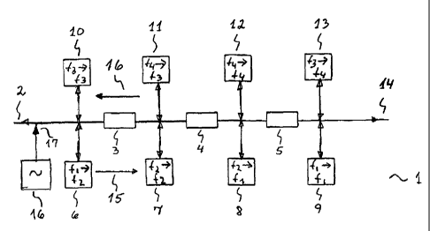
Fig. 1 illustrates how the invention in a repeater system 1 or a repeater
cascade 1 makes use of frequency transposing repeaters where isolation against
echo between repeaters is made redundant by the use of three frequency bands,
f1, f2, f2 for each information channel, possibly each signal direction in
use. The
figure shows in more detail how the invention makes use of a repeater cascade
1
with the help of frequency transposing repeaters 6, 8 in combination with
repeaters
that amplifies within the same channel 7, 9 by applying only two frequency
bands,
f1 and f2 for on and the same information channel. This is achieved in a
symmetrical system by repeater 6 frequency shifting from frequency f1 to f2.
The
nest repeater 7 repeats the signal within the same frequency band, f2. The
next
repeater 8 repeats by frequency shifting to f1. Further on the sequence is
repeated starting with the subsequent attenuation 5 and repeater 9. In this
way
echo for example into one repeater 6 from a different repeater 8 is avoided
because the gain in each individual repeater 6, 7, 8 is substantially lower
than the
CA 02552636 2006-07-05
WO 2005/067164 PCT/N02005/000013
14
attenuation 3, 4 between three repeaters. This results in optimal signal
dynamics.
Correspondingly the invention facilitates the same method to be used in the
opposite direction 16 in an asymmetrical or symmetrical system or system that
needs two information channels by utilising repeaters 10-13 for the frequency
bands f3 and f4. One or more pilot signals 16 can be inserted in one or more
points 17 in the signal cascade 2, 14 to ease automatic adjustments of the
gain in
each repeater 6-9, 10-13. When the liberty to determine freely the physical
distance and position for repeaters is available as is the case on open power
transmission lines or ground lines in such systems, the invention allows the
insertion of an additional 20 dB isolation in the same frequency channel by
making
every other distance between the repeaters larger to result in approximately
20 dB
additional attenuation. About 20 dB reduction of transmission power is
allowable
without causing undesired effects, therefore the invention can be realised in
such
a way that every other repeater has an output level of for example OdBm while
correspondingly every other repeater has -10dBm. Alternatively, the difference
in
output power may be adjusted automatically with AGC arrangements possibly by
the help pilot signals between the repeaters.
In fig. 2 is shown an example of repeater as described in patent publications
N020001057, N020010132, N020020112, PCT/N001/00079, PCT/N003/00004
which is a double or multiple super heterodyne repeater 38 where in the
invention
it is arranged with a signal intermediate frequency 33 being suitable for
adaptation
to an analogue repeater 38 using for example a common intermediate frequency
25, 31 with an adapter 36 for wireless modem or other commercially available
modem or network node 36 which may be a IEEE802.11x node or modem 36 or
Docsis node or modem 36. The invention may also be used for symmetrical
modems that can be interconnected back to back almost anywhere in the system
and independently of which modulation or protocol the system is using in such
a
way that the invention facilitates the use of differing, standardised
modulation
types and protocols within one and the same system, for example to achieve
adaptive qualities and longer range in a low cost manner in parts of the
system,
possibly with the penalty of reduced bandwidth in parts of the system. If such
modems use base band a modulator and demodulator is required, preferably of
the I/Q type, and inserted in connection with the adapter 36 if higher
frequency
bands are to be used for the transmission between the back to back modems.
CA 02552636 2006-07-05
WO 2005/067164 PCT/N02005/000013
Such typical modems are DSL modems, for example HDSL The invention also
encompass viable corresponding arrangements using super regenerative repeater
38 which eventually would use intermediate frequency 25, 31 with the help of
the
super heterodyne principle. The repeater may be interconnected in the cascade
5 as a two port through circuits 21, 26 or as a one port with the aid of the
circuit 39.
In fig. 3 it is shown how the invention facilitates bi-directional frequency
mixing in
an adapter 41 with signal frequency 43 that may be a microwave signal
frequency
43 of a commercially available type network node 42, which may conveniently be
a
wireless modem 42, to this intermediate frequency whereby such a modem 42 or a
10 node 42 or PC adapter 42 can be connected at any point 51 where a repeater
38
of the type described in fig. 2 is present and which contain frequency
corresponding to intermediate frequency 45, 49, 50. The repeater 41 is
connected
at any point 51 in an analogue signal cascade 52. Bi-directional frequency
conversion can be applied using a bi-directional frequency converter 44 such
as a
15 diode ring mixer, still simpler bi-directional diode mixers or as two
separate
frequency mixers. Additionally, gain 48, 49 can be included in the invention.
If the
node 42 does not have a removable antenna 53, the connection between adapter
41 and node 42 can be satisfied using a loose coupling 53 to the antenna
corresponding to signal point 53.
In fig. 4 one arrangement of the invention is shown with an adapter solution
61 corresponding to the one in figure 2. Here it is shown how the invention in
addition to frequency converter 64 using level adapting characteristics
facilitates
the arrangement of a bypass signal path 63, 65-69, with or without frequency
conversion, for return signals 63 using a stop filter 69 for the available
frequency
band in the forward direction 62 to achieve acceptable duplex characteristics.
In fig. 5 a novel method of combining 70 bi-directional gain with isolation
between input signal and output signal 73-76 is accomplished for a repeater 70
with antennas 71, 72, antenna like couplers 71, 72 or other types of couplers
71,
72 as well as avoidance of reflections back to the repeaters 82, 83. This is
achieved in the invention using two frequency bands with two repeaters 82, 83
that
repeats within the same frequency bands 74-76, 73-75 but where the two bi-
directional, conveniently one-port repeaters 82, 83 have differing frequency
bands
for the two signal directions 74-76, 73-75. In addition, the invention can
utilise
separate amplifiers 77-80, 78-79 for added isolation for input and output
signals
CA 02552636 2006-07-05
WO 2005/067164 PCT/N02005/000013
16
76-73, 75-74 and opposite antenna polarisation, differing coupler polarity or
differing cable phases for the differing signal directions 73-74, 75-76 or for
the
differing ports 74-76, 72-75. For radio or applications similar to radio,
circular
polarisation may conveniently be used. The repeater arrangement can carry
built
in radio interface 81 of any type preferably one with low current draws and in
which analogue technology described in patent publications N020001057,
N020010132, N020020112, PCT/N001/00079, PCT/N003/00004can be applied.
The radio interface can be two-way and can be used as a none galvanic coupling
to the outside world which typically will be another radio unit at close
range. The
invention is suitable for radio applications where the repeaters 70 is to
consume
little energy, similarly it is suitable for repeater 70 on conductors that are
brought
to act according to the Lecher wire principle.
Fig. 6 shows that the invention can make use of the fact that any physical
point on a cable where conductors are accessible either implicit or through
simple
measures between two junctions can be viewed as consisting of a two port 90
consisting of three parts 91, 92, 93, two ports 98 and 97, 94 and 95 including
a
transfer function 92 between them. The transfer function 92 can be given by
the
properties of each conductor 114 where the point 110 can consist of one or
more
junctions, stray capacitance, inductance and various loss functions.
Correspondingly is provided for two conductors 109, 101, 102 or for two
conductors 121, 122, 123 in a three conductor system 120 and so on and without
significant affect on the use of two or more conductors in differential
couplings.
Fig. 7 shows that the invention makes use of changing the magnetic field
around the conductor preferably by toroids 140, in most cases being
practicably
installable 141, 142, 143 on each conductor 154, 155, 156. The invention can
advantageously make use of toroids of magnetic materials. But it is also
possible
to use toroids of dielectric material since materials with very high
dielectric
constants have become commercially available. With respect to toroids the
effect
is increased by increasing the toroid length or by stacking a number of
toroids. In
the invention each conductor 150 with a junction will consist of three
separated
toroids 154-156, for a three phase cable system 160 with a one phase junction
163 the invention will typically consist of 8 toroids.
Fig. 8 shows that a two pole according to the invention may be decomposed
into various impedances 170, Z1-Z9 that may be simulated using computer. A
CA 02552636 2006-07-05
WO 2005/067164 PCT/N02005/000013
17
single conductor 180 with a junction though a typical junction box within a
power
grid system will typically exhibit 12 dB or more attenuation between any of
the
"ports" using galvanic coupling. Without toroids the attenuation will be
limited to
around 6 dB. For a reflection this means a dampening of 24 dB and an
improvement of 12 dB. The invention will exhibit somewhat lower attenuation
with
air mounted cables. By inserting an extra high frequency impedance in Z9, 170,
between the ports, preferably consisting of a capacitor in series with a low
resistance value, these figures are usually improved by several dB.
Fig. 9 shows repeaters 195, 198, 201, 218, 219, 235 preferably for two way
transmission of relatively large bandwidths across relatively long ranges on
single
conductors 191-193, 211-213, 232 especially on open power lines that carry
from
a few kilovolts and up to Megavolts or mast mounted ground lines in connection
with such power lines using compact, practical analogue repeaters. This then
concerns also when the repeaters are installed on the ground line 241 or
ground
lines 241. The invention in one realisation can in a given repeater point 190,
210,
230 two repeaters in each unit 195, 198, 201, 218, 219, 235 that repeats
within the
same frequency band where the repeaters within each unit 195, 198, 201, 218,
219, 235 satisfies today's coexistence requirements and where the two
repeaters
utilise differing frequency bands for the two signal directions 203, 204.
In addition the invention can apply opposite antenna polarisation 194-196,
197-199, 200-202 for the differing signal ports. The polarisation can be
circular or
linear and be in the form of an antenna 194, 196, 197, 199, 200, 202, antenna
element 194, 196, 197, 199, 200, 202 or probe 194, 196, 197, 199, 200, 202 and
a
reflector can be used. In one embodiment of the invention the repeaters can be
installed on different conductors 211, 213 in a mast power line system to
better
separate the two signal directions. Correspondingly one embodiment of the
invention can be arranged to utilise frequency shifting repeaters 195, 198,
201,
218, 219, 235. Suitable repeaters for the purpose is also described in patent
publications N020001057, N020010132, N020020112, PCT/N001/00079,
PCT/N003/00004.
Fig. 10 shows that the principle 250 of none galvanic coupling of the
invention is a coupler conductor loop 252 where the one part of the loop is
lead at
a certain length very close to the cable conductor 251 to which coupling is
intended. If the cable conductor and the closest loop conductor is carried
through
CA 02552636 2006-07-05
WO 2005/067164 PCT/N02005/000013
18
a toroid 253 of magnetic or dielectric material the coupling is increased. The
circuit
arrangement 250 of the invention can be made still more efficient by the
referenced loop conductor 252 being wound as a few turns around the toroid
253.
Still more improvement of the coupling 260 results when in the invention a
number
of toroids 263, 264 are stacked and where the cable conductor 261 and the loop
conductor 262 are passed through the stacked toroids.
Fig. 11 shows that differential coupling in the invention using two cable
conductors is achieved by employing a corresponding arrangement on the other
cable conductor and making the loop conductor 314 pass through both toroids
316, 317 in the same manner. Multiple phase couplings can be realised
correspondingly. A simple form of matching is achieved using a resistance 318
in
series with the coupler loop 313.
Fig. 12 shows that the invention can make use of any phase combination
330 and this may be programmable or adaptive for example by using a simple
circuit with a switch 334 for example by using a common coupler loop conductor
335.
Fig. 13 shows a coupler arrangement 360 with two cable junctions 361, 362
with two separate coupler loops 363, 365 with increased mutual attenuation
between coupler loops 363, 365 that can be optimised using an additional load
impedance inserted in the middle of the circuit in addition to the implicit
371.
Correspondingly 390 the invention gives isolation between all coupler loops
363,
365, 381 when there are more than two such coupler loops, for example as in
the
case of three cable junctions 361, 362, 380 using three none galvanic
couplers.
The invention makes it possible to combine galvanic and none galvanic
coupling,
for example by using galvanic coupling for one signal direction carrying the
lowest
frequency content where none galvanic coupling is less efficient and where the
galvanic coupling can be made on the terminals 361, 362.