Note: Descriptions are shown in the official language in which they were submitted.
CA 02552863 2006-07-07
WO 2005/070110 PCT/US2005/000617
MULTILUMEN CATHETERS AND METHODS FOR THEIR USE
CROSS-REFERENCE TO RELATED APPLICATIONS
~o~~ This application claims priority (pursuant to 35 U.S.C. ~ 119 (e)) to the
filing
date of United States Provisional Patent Application Serial No. 60/535,618
filed
on January 9, 2004; the disclosure of which is herein incorporated by
reference.
INTRODUCTION
Field of the Invention
~02~ The field of this invention is atherosclerosis and related vascular
conditions,
and particularly catheter devices used for treating such conditions.
Background of the Invention
103 The formation of plaques or lesions (atherosclerotic plaques or lesions),
on
vascular tissue, such as the inner surface of blood vessels, aortic valves,
etc.,
is a major component of various vascular disease conditions. For example,
plaques on heart related vascular structures, e.g., coronary artery intima,
heart
valves, etc., are often implicated in various heart disease conditions.
Likewise
plaques or lesions present on the intima of peripheral vessels, e.g.,
arteries, are
often implicated in various peripheral vascular disease conditions.
~04~ A variety of different protocols have been developed for treating
diseases
associated with the presence of vascular lesions or plaques. Such treatment
methodologies generally involve mechanical removal or reduction of the lesion,
and include: bypass surgery, balloon angioplasty, mechanical debridement,
atherectomy, valve replacement, and the like. Despite the plethora of
different
treatment strategies that have been developed for the treatment of such
vascular disease conditions, there are disadvantages associated with each
technique, such as tissue damage, invasiveness, etc. For example, restenosis
is a common complication that results in arteries in which lesions have been
mechanically removed.
(os~ As such, there is continued interest in the development of new treatment
protocols for the removal of vascular lesions from vascular tissue, as well as
catheter devices that are used in such protocols.
1
CA 02552863 2006-07-07
WO 2005/070110 PCT/US2005/000617
Literature
~os~ U.S. Patents of interest include: 4,329,994; 4,838,881; 5,149,330;
5,167,623; 5,207,6485; 542,937;6,004,310; and 6,013,068. Also of interest are
U.S. Patent Nos.: 4,445,892; 4,573,966; 4,610,662; 4,636,195; 4,655,746;
4,824,436; 4,911,163; 4,976,733; 5,059,178; 5,090,960; 5,167,628; 5,195,955;
5,222,941; 5,380,284; 5,443,446; and 5,462,529. See also: WO 00/03651; WO
01 /13985; WO 01 /15767; WO 01 /39783; WO 01 /70320; and WO 02/15958; the
disclosures of the priority documents of which are herein incorporated by
reference.
SUMMARY OF THE INVENTION
~07~ Multilumen aspiration and delivery catheters, as well as methods for
their
use, are provided. The subject multilumen catheters include a proximal end and
a distal end separated by a non-coaxial multilumen tube. Also provided are
systems for use in flushing a vascular site with fluid, usually at least two
different fluids, where the subject systems are made up of a delivery catheter
inside of an aspiration catheter. In addition, kits comprising various
components of the subject systems, e.g., at least two different multilumen
catheters, are provided. The subject multilumen aspiration and delivery
catheters, systems and kits find use in a variety of different applications in
which it is desired to flush a vascular site with at least one and preferably
two
different fluids, where particular applications of interest include the
treatment of
vascular lesions, including coronary artery vascular lesions.
BRIEF DESCRIPTION OF THE FIGURES
~os~ Each of the following figures provides examples diagrammatically
illustrating
aspects of the present invention.
~os~ Figs. 1A and 1 B each provide a representation of an aspiration catheter
according to the subject invention.
~~o~ Figs. 2A and 2B each provide a representation of a total occlusion
catheter
according to the subject invention.
Figs. 3A and 3B each provide a 'representation of a partial occlusion
catheter according to the subject invention.
2
CA 02552863 2006-07-07
WO 2005/070110 PCT/US2005/000617
~~z~ Fig. 4 provides a representation of a total occlusion catheter system
according to the subject invention.
Fig. 5 provides a representation of a partial occlusion catheter system
according to the subject invention.
DESCRIPTION OF THE SPECIFIC EMBODIMENTS
~~a.~ Multilumen aspiration and delivery catheters, as well as methods for
their
use, are provided. The subject multilumen catheters include a proximal end and
a distal end separated by a non-coaxial multilumen tube. Also provided are
systems for use in flushing a vascular site with fluid, usually at least two
different fluids, where the subject systems are made up of a delivery catheter
inside of an aspiration catheter. In addition, kits comprising various
components of the subject systems, e.g., at least two different multilumen
catheters, are provided. The subject multilumen aspiration and delivery
catheters, systems and kits find use in a variety of different applications in
which it is desired to flush a vascular site with at least one and preferably
two
different fluids, where particular applications of interest include the
treatment of
vascular lesions.
~~s~ Before the present invention is described in greater detail, it is to be
understood that this invention is not limited to particular embodiments
described, as such may, of course, vary. It is also to be understood that the
terminology used herein is for the purpose of describing particular
embodiments only, and is not intended to be limiting, since the scope of the
present invention will be limited only by the appended claims.
~~s~ Where a range of values is provided, it is understood that each
intervening
value, to the tenth of the unit of the lower limit unless the context clearly
dictates otherwise, between the upper and lower limit of that range and any
other stated or intervening value in that stated range is encompassed within
the
invention. The upper and lower limits of these smaller ranges may
independently be included in the smaller ranges is also encompassed within
the invention, subject to any specifically excluded limit in the stated range.
Where the stated range includes one or both of the limits, ranges excluding
3
CA 02552863 2006-07-07
WO 2005/070110 PCT/US2005/000617
either or both of those included limits are also included in the invention.
Unless defined otherwise, all technical and scientific terms used herein have
the same meaning as commonly understood by one of ordinary skill in the art to
which this invention belongs. Although any methods and materials similar or
equivalent to those described herein can also be used in the practice or
testing
of the present invention, the preferred methods and materials are now
described.
~~s~ All publications and patents cited in this specification are herein
incorporated
by reference as if each individual publication or patent were specifically and
individually indicated to be incorporated by reference and are incorporated
herein by reference to disclose and describe the methods and/or materials in
connection with which the publications are cited. The citation of any
publication
is for its disclosure prior to the filing date and should not be construed as
an
admission that the present invention is not entitled to antedate such
publication
by virtue of prior invention. Further, the dates of publication provided may
be
different from the actual publication dates which may need to be independently
confirmed.
[19] It must be noted that as used herein and in the appended claims, the
singular forms "a", "an", and "the" include plural referents unless the
context
clearly dictates otherwise. It is further noted that the claims may be drafted
to
exclude any optional element. As such, this statement is intended to serve as
antecedent basis for use of such exclusive terminology as "solely," "only" and
the like in connection with the recitation of claim elements, or use of a
"negative" limitation.
~20~ As will be apparent to those of skill in the art upon reading this
disclosure,
each of the individual embodiments described and illustrated herein has
discrete components and features which may be readily separated from or
combined with the features of any of the other several embodiments without
departing from the scope or spirit of the present invention. Any recited
method
can be carried out in the order of events recited or in any other order which
is
logically possible.
~2~~ In further describing the subject invention, the subject multilumen
catheters
4
CA 02552863 2006-07-07
WO 2005/070110 PCT/US2005/000617
are described first, both generally and in terms of the figures, followed by a
description of the subject systems, kits and representative methods in which
the catheters, systems and kits find use.
MULTILUMEN CATHETERS
~z2~ As summarized above, the present invention provides multilumen catheters.
Specifically, the subject invention includes three different multilumen
catheters,
which can be used together as a system to simultaneously flush a vascular site
with two distinct fluids. A common feature of each catheter of the subject
invention is that they include a proximal end and a distal end separated by an
elongated non-coaxial multilumen tube. By non-coaxial multiluriieri tube, it
is
meant a tube that includes at least two lumens that are non-coaxial, i.e.,
they
do not share a common axis. The number of lumens in the multilumen tube
may vary, but generally is 2 to 5, and is often 2 to 4, where in certain
embodiments the number is 2 or 3. By elongated, it is meant that the distance
between the proximal and distal ends is sufficient for the catheter to be
inserted
or introduced into the vascular system of a patient at a site remote from the
vascular lesion that is to be treated through action of the distal end of the
catheter, as is known in the art. Catheters intended for intravascular
introduction will typically have a length in the range from 50 cm to 200 cm
and
an outer diameter in the range from 1 French (0.33 mm; Fr.) to 12 Fr., usually
from 3 Fr. to 9 Fr. In the case of coronary catheters, the length is typically
in the
range from 125 to 200 cm, the diameter is preferably below 8 Fr., more
preferably below 7 Fr., and most preferably in the range from 2 Fr. to 7 Fr.
In
certain embodiments, the elongated tubular element has a length of from about
80 to 200 cm, usually from about 90 to 180 cm and more usually from about 90
to 140 cm.
[23] All of the subject multilumen catheters are further characterized in that
they
include a multiport manifold at their proximal ends. By multiport manifold is
meant a manifold that includes two or more ports (in addition to the
attachment
structure of the mannifold to the proximal end of the elongated tube of the
catheter), where the number of ports in the manifold may range from 2 to 4,
CA 02552863 2006-07-07
WO 2005/070110 PCT/US2005/000617
depending on the particular multilumen catheter. In addition, at least one of
the
ports of the multiport manifold preferably has an attachment element for
establishing a sealed fluid communication with the lumen of an external
tubular
element or analogous fluid conveying means, where this attachment structure
is generally referred to herein as a luer-type connector or a luer-valve,
where
many different luer-type connectors or analogous attachment elements are
known to those of skill in the art. In many embodiments, a luer valve is
present
at one or more ports of the multiport manifold, where the valve may be a male
or female luer valve. Luer valves are disclosed in U.S. Patent Nos. 6,063,062;
6,039,302; 5,954,313; 5,947,954; 5,788,215; 5,775,671; 5,738,144; 5,549,651;
5,535,785; 5,474,544; 5,441,487; 5,372,143; 5,284,475; the disclosures of
which are herein incorporated by reference.
Another common feature of all of the multilumen catheters of the subject
invention is that the elongated multilumen tube is typically a polymeric
extruded
element, which is made up of one or more biocompatible polymers that have
been extruded to produce the non-coaxial multilumen tube. Biocompatible
polymers of interest include, but are not limited to: polyimide, polyamide,
PBAXTM, polyethylene, polyisoprene, nylon and the like.
~ZS~ Although each of the disparate multilumen catheters share the above
common features, there are differences between the different specific
multilumen catheter designs of the subject invention. As such, each specific
type of multilumen catheter of the subject invention, e.g., aspiration, total
and
partial multilumen catheters, will now be described separately in greater
detail.
Aspiration Catheter
~ZS~ The multilumen aspiration catheter of the subject invention is identified
herein as the aspiration catheter, as it includes the lumen employed for
aspiration when the catheter is used in a system for flushing a vascular site
with
fluid. The aspiration catheter is characterized by having a proximal end and a
distal end separated by a non-coaxial three-lumen tube, where a four-port
manifold is present at the proximal end. In the four-port manifold, at least
three
of the ports typically have luer type connectors, e.g., luer valves, while the
6
CA 02552863 2006-07-07
WO 2005/070110 PCT/US2005/000617
fourth port has a valve capable of opening and closing around a tubular
element, e.g., a delivery catheter, dilator, guidewire, etc., to produce a
sealed
relationship with the tubular element. In many embodiments, this sealing
element is a Touhy-Borst valve or analogous structure, where Touhy-Borst
valves are known to those of skill in the art and described in IJ.S. Pat.
Nos.:
5,795,307 and 5,320,613; the disclosures of which are herein incorporated by
reference.
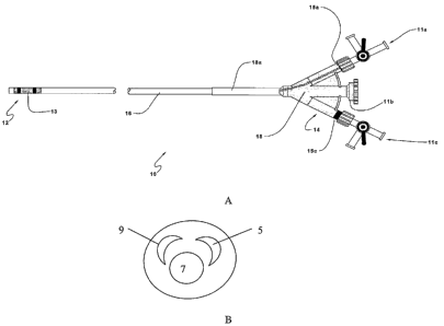
Figs. 1A and B provide a depiction of a representative aspiration catheter
according to the subject invention. In Fig. 1A, aspiration catheter 10 has
proximal end 14 and distal end 12 separated by elongated non-coaxial three-
lumen tube 16. The length of elongated tube 16 should be long enough to
provide for access of the distal end to the target vascular site upon
introduction
into the host, subject or patient at a remote site, and typically ranges from
about
80 to 200 cm, usually from about 90 to 180 cm and more usually from about 90
to 140 cm. The outer diameter of the elongate tubular member 16 may vary
depending on the target vascular site for which it is designed to be used. In
other words, the outer diameter of the aspiration catheter is selected so as
to
provide for access of the distal end of the catheter to the vascular site via
the
vascular system from the remote point of entry, where the outer diameter
typically ranges from about 1.0 to about 12.0 Fr., usually from about 1.0 to
about 9.0 Fr. and more usually from about 1.0 to about 8.0 Fr. In the case of
coronary catheters, the length is typically in the range from 125 to 200 cm,
the
diameter is typically below about 8.0 Fr., often below about 7.0 Fr., and
typically
in the range from about 2.0 Fr. to about 7.0 Fr.
~ZS~ The aspiration catheter is further characterized in that one of the three
lumens, generally the larger of the three lumens, opens at the distal end,
thereby providing a fluid entry site for fluid from the target vascular site
to flow
into the lumen. In Fig. 1 B, this larger lumen is designated 7. The inner
diameter of this lumen at the open distal end and along the entire length of
the
tube 16 is sufficient to house either a partial or total occlusion multilumen
catheter, as described in greater detail below, and remove fluid from the
vascular site at the desired rate, e.g., a rate that provides for
substantially
isometric or isobaric pressure in the vascular site during treatment, through
the
7
CA 02552863 2006-07-07
WO 2005/070110 PCT/US2005/000617
resultant annular space. This larger lumen 7 is also known as the aspiration
lumen. The inner diameter of the aspiration lumen 7, at least at its distal
end
and generally along the entire length of the aspiration catheter, is
sufficient to
provide for adequate flow into the lumen of the catheter, and sometimes ranges
from about 0.20 to 2.0, usually from about 0.25 to 1.75 and more usually from
about 0.35 to 1.5 mm.
~as~ Also present at the distal end of the aspiration catheter .10 is a vessel
occlusion means 13, where the vessel occlusion means is usually an inflatable
balloon. The balloon 13 is one that is inflatable to a volume sufficient to
substantially occlude the vessel in which the aspiration catheter is
positioned,
e.g., by pressing against the intimal surface of the vessel in which the
aspiration catheter is positioned. The inflated balloon diameter generally
ranges from about 2 to 30 mm, usually from about 5 to 20 mm. The inflated
balloon length typically ranges from about 10 to 30 mm, usually from about 15
to 20 mm. The balloon is in fluid or gaseous communication with an inflation
lumen 9 that is a second lumen of the three-lumen tube and runs the length of
the aspiration catheter from the balloon to the proximal end, but does not
open
up at the distal end of the catheter. The inflation lumen typically has an
inner
diameter that ranges from about 0.1 to about 0.5 mm, usually from about 0.2 to
about 0.4 mm. In certain embodiments, the aspiration catheter further includes
a separate guidewire lumen (not shown). However, in many embodiments, a
separate guidewire lumen is not present.
~30~ The third lumen of the three-lumen tube is typically employed for
delivery of
a dissolution fluid attenuating fluid to the target vascular site, e.g., for
delivery of
a bufFer solution to the target vascular site. The cross-sectional area of
this
dissolution fluid delivery lumen 5 typically ranges from about 0.03 to about
0.8
mm2, usually from about 0.03 to about 0.4 mmz and more usually from about
0.07 to about 0.2 mm2.
While the configuration of the representative three-lumen aspiration
catheter depicted in Figures 1A and B shows circular and crescent shaped
lumens, other configurations are also possible, e.g., two circular lumens, to
semicircular lumens, etc.
~32~ At the proximal end 14 of aspiration catheter 10 is four-port manifold 18
s
CA 02552863 2006-07-07
WO 2005/070110 PCT/US2005/000617
(note that one of the ports is not shown in the figure). Four-port manifold 18
includes side or offset ports 11 a, 11 c and 11 d (not shown), as well as
central
port 11b. One of the offset ports, e.g., 11a is in fluid communication with
the
smaller lumen 9 and is attached to a balloon inflation means, e.g., a syringe
filled with gas or fluid, during use. The second offset port, e.g., 11c, is in
fluid
communication the larger aspiration lumen 7 and is attached to a source of
negative pressure, e.g., a vacuum, during use. The third offset port, 11 d, is
in
fluid communication with a source or reservoir of dissolution fluid
attenuating
fluid. Offset ports 11 a, 11 c and 11 d (not shown) are further characterized
in
having or being in communication with luer valves 15a, 15c and 15d (not
shown), respectively, for making connections with fluid conveyance means. In
many embodiments, luer valves 15a, 15c and 15d (not shown) are female luer
valves. Central port 11 b is in fluid communication with the aspiration lumen
7
and provides the point of access for the total and partial occlusion
catheters,
described in greater detail below. As such, in the manifold 18 of the
aspiration
catheter, two of the ports of the manifold, specifically the central port and
one of
the offset ports, are in fluid communication with the aspiration lumen 7.
Central
port 11 b is characterized by the presence of Touhy-Borst valve 15b or an
analogous structure. Touhy-Borst valves suitable for use in medical devices,
e.g., catheters, are known in the art and described in U.S. Patent No.
5,320,613
and 5,795,307; the disclosures of which with respect to such valves are herein
incorporated by reference.
[33] AISO present on the catheter shown in Fig. 1A is a strain relief 18a. The
strain relief protects the proximal end of tube 16 from damage and gives
strength to the transition between the tube and manifold 18. The strain
relieve
locally increases the stiffness of tube 16 to provide a moderated step-wise
increase in stiffness from the relatively more flexible tube to the stiffer
manifold
member. The length of the strain relieve may vary from about 5 to about 40
mm, but is usually about 20 to about 30 mm in length. Suitable materials for
strain relief 18a include fluorinated ethylene-propylene or a similar medical
grade polymer.
~sa.~ The embodiment shown in Fig. 1A includes three-way stop cocks attached
to each of the offset ports. These elements provide for further control of
fluid
9
CA 02552863 2006-07-07
WO 2005/070110 PCT/US2005/000617
flow into the lumens of the device and/or the introduction of two separate
fluids
into the same lumen of the device, e.g:, an imaging solution into the
aspiration
lumen and aspiration of fluid through the aspiration lumen, depending on the
state of the three -way stop-cock.
~3s~ For convenience during use of the aspiration catheter, each of the ports
of
the four-port manifold may be uniquely identified, e.g., color coded, so that
it is
readily apparent as to the element that the port should be connected during
use
of the device, e.g. vacuum source, balloon inflation means, etc. For example,
one of the offset ports may have a yellow band, one may have a green band,
one may have a blue band and one may have a red band, thereby uniquely
identifying the ports of the four-port manifold.
Total Occlusion Multilumen Catheter
~3s~ Also provided by the subject invention are multilumen delivery catheters
that
are designed to be inserted inside the aspiration lumen and used to flush a
vascular site that is characterized by the presence of a total vascular
occlusion,
e.g., as described in greater detail below. These fluid "delivery" catheters
are
identified herein as total occlusion catheters. In general, the total
occlusion
catheters are characterized in that the multilumen tube separating the
proximal
and distal ends is a two-lumen tube. These total occlusion catheters are
further
characterized in that the multiport manifold is preferably a two-port
manifold,
where one of the ports has a luer valve or analogous element, as described
above, and the other port has a Touhy-Borst valve or analogous element.
Figs. 2A and B provide a representation of a total occlusion catheter
according to the subject invention. As shown in Fig. 2A, total occlusion
catheter
20 includes proximal end 24 and distal end 22 separated by elongated tubular
member 26. Elongated tubular member 26 is sufficiently long to provide for
access of the distal end to the target vascular site upon introduction into
the
host vascular system via a remote entry site of the vascular system.
Typically,
the length of elongate member 26 ranges from about 90 to about 210 cm,
usually from about 100 to about 190 cm and more usually from about 110 to
about 150 cm. The outer diameter of the tubular member 26 is such that it may
CA 02552863 2006-07-07
WO 2005/070110 PCT/US2005/000617
be slidably positioned inside the aspiration lumen of the aspiration catheter,
as
described above. Typically, the outer diameter of element 26 ranges from
about 1.5 to about 6.0 Fr, usually from about 2.5 to about 5.0 Fr.
~3s~ Tubular member 26 is a two-lumen tubular member, where the lumens of
the catheter are non-coaxial. In the embodiment depicted in Figures 2A and 2B,
each of the lumens, 25 and 27, open at the distal end of catheter 20. One of
the
lumens, e.g., 27, is designed to carry a dissolution fluid and the other
lumen, 25
is designed to carry a guidewire. The configuration of the each of the lumens
in
the embodiment shown in Fig. 2A can be seen in Fig. 2B, which is a cross
section of tubular member 26 taken at line A-A shown in Fig. 2A. As can be
seen in the representative embodiment, guidewire lumen 25 has a substantially
circular configuration while dissolution fluid delivery lumen 27 has a
crescent
configuration so as to share a common wall or border with a substantial
portion
of lumen 25, where by "substantial portion" is meant at least 25%, usually at
least 35% and more usually at least 50% of the circumference of lumen 25,
where in certain embodiments this portion may be much higher, e.g., 60%, 75%
etc. Lumen 25 is typically employed for conveying the dissolution fluid while
lumen 27 is typically employed for a guidewire.
The inner diameter of lumen 25 typically ranges from about 0.2 to about 1.0
mm, usually from about 0.2 to about 0.7 mm and more usually from about 0.3
to about 0.4 mm, so as to provide for a cross-sectional area of about 0.03 to
about 0.8 mm2, usually from about 0.03 to about 0.4 mm2 and more usually
from about 0.07 to about 0.2 mm2. The cross-sectional area of lumen 27
typically ranges from about 0.03 to about 0.8 mm2, usually from about 0.03 to
about 0.4 mm2 and more usually from about 0.07 to about 0.2 mm2. While the
configuration of Fig. 2B shows a circular and crescent shaped lumen, other
configurations are also possible, e.g., two circular lumens, to semicircular
lumens, etc.
~a.o~ Also present on the preferred total occlusion catheter at proximal end
24 is
two-port manifold 28. Two-port manifold 28 includes side or offset port 21 a
and
central port 21 b. Port 21 a includes female luer valve 23a while port 21 b
includes Touhy-Borst valve 23b. During use, side or offset port 21a is
typically
in fluid communication with a source of dissolution fluid attenuating fluid,
e.g.,
11
CA 02552863 2006-07-07
WO 2005/070110 PCT/US2005/000617
buffer, while central port 21 b is typically sealed around a guidewire.
~a.~~ Also present on the catheter shown in Fig. 2A is a strain relief 28a. It
functions as described in connection with strain relief 18a. In the embodiment
shown in Fig. 2A, also present is three-way stop cock attached to the central
port which provides for further control of fluid flow into the central lumens
of the
device, the introduction of two separate fluids into the same lumen of the
device
and/or the introduction of separate fluids for intermittent flushing, e.g.
with
heparinized saline, typically used to keep lumens clear and prevent clotting.
~42~ For convenience during use of the aspiration catheter, each of the ports
of
the two port manifold may be uniquely identified, e.g., color coded, so that
it is
readily apparent as to the element that the port should be connected during
use
of the device, e.g. dissolution fluid reservoir, dissolution fluid attenuating
fluid
reservoir, etc. For example, one of the offset ports may have a yellow band
and
one may have a red band, thereby uniquely identifying the ports of the
manifold.
Partial Occlusion Catheter
[43] AISO provided by the subject invention are multilumen catheters that are
designed to be inserted inside the aspiration lumen and used to flush a
vascular site that is characterized by the presence of a partial vascular
occlusion. These catheters are identified herein as partial occlusion
catheters.
In general, the partial occlusion catheters are characterized in that the
multilumen tube separating the proximal and distal ends is a three-lumen tube.
These partial occlusion catheters are further characterized in that the
multiport
manifold is a three-port manifold, where two of the ports has a luer valve or
analogous structure and the third port has a Touhy-Borst valve or analogous
structure for making a sealing engagement with a guidewire inserted
therethrough. In addition to the above features, the partial occlusion
catheter
also includes a balloon or analogous vessel occlusion means at its distal end
and at least one port, and often multiple ports, proximal to the balloon,
where
these infusion ports are in fluid communication with one of the lumens.
Figs. 3A and B provide a representation of a partial occlusion catheter
12
CA 02552863 2006-07-07
WO 2005/070110 PCT/US2005/000617
according to the subject invention. As shown in Fig. 3A, partial occlusion
catheter 30 includes distal end 32 and proximal end 34 separated by three
lumen tube 36. The length of the tubular member 36 generally ranges from
about 90 to about 250 cm, usually from about 100 to about 230 cm and more
usually from about 110 to about 190 cm. The outer diameter of the tubular
member 36 is such that the partial occlusion catheter 30 may be slidably
positioned in the aspiration lumen of the aspiration catheter. As such, the
outer
diameter of tubular member 36 typically ranges from about 0.5 to about 2.0,
usually from about 0.8 to about 1.6 mm.
~a.s~ Located at the distal end of catheter 30 is balloon 31 or analogous
occlusion
means. The balloon is generally one .that is inflatable to a diameter ranging
from about 2 to about 15 mm, usually about 5 to about 10 mm, and typically
has a length of from about 10 to about 30 mm, usually from about 15 to about
20 mm.. Proximal to the balloon 31 are a series of ports 43, 45 and 47 which
provide for fluid transfer between the outside of tube 36 and the fluid
delivery
lumen located inside the device, i.e., a first lumen inside the tube 36 that
is
carrying a dissolution fluid. The diameter of the infusion ports may vary, but
typically ranges from about 0.2 to about 1.2, usually from about 0.4 to about
1.0
and more usually from about 0.5 to 0.8 mm.
~4s~ A representative configuration of the three lumens of multilumen tube 36
is
shown in Fig. 3B, which shows the cross section of tube 36 taken along line A-
A as shown in Fig. 3A. As shown in Fig. 3B, lumen 37 has a substantially
circular cross section and is designed to provide a passage for a guidewire,
while lumens 39 and 41 together make up a crescent shape that shares a
border with lumen 37 that extends for a substantial portion of the perimeter
of
lumen 37. The crescent shape made through combination of lumens 39 and 41
is divided to provide for distinct lumens 39 and 41. The diameter of .lumen 37
typically ranges from about .02 to about 1.0 mm, usually from about 0.2 to
about 0.7 mm and more usually from about 0.3 to about 0.4 mm to provide a
cross-sectional area ranging from about 0.03 to about 0.8 mm2, usually from
about 0.03 to about 0.4 mm2. The cross sectional area of lumen 39 typically
ranges from about 0.03 to about 0.8 mm2, usually from about 0.03 to about 0.4
mm2 while the cross-sectional area of lumen 41 typically ranges from about
13
CA 02552863 2006-07-07
WO 2005/070110 PCT/US2005/000617
0.05 to about 0.3, usually from about 0.1 to about 0.2. In many embodiments,
lumen 37 conveys a guidewire, lumen 39 conveys dissolution fluid, e.g., acid,
and lumen 41 conveys inflation medium, e.g., gas or fluid, to the balloon.
While
one type of configuration of the various lumens is shown, other non-coaxial
configurations are also possible, e.g., three separate circles, a circle and
two
distinct crescent shapes, etc., where all of these potential configurations
are
within the scope of the invention.
~a.7~ Located at the proximal end 34 of catheter 30 is three-port manifold 38.
Three- port manifold 38 includes two offset or side ports 33a and 33c, which
flank central port 33b. The two side ports each include a female luer valve,
35a,
35b and 35c. The central port 33b includes Touhy-Borst valve 35b for
producing a sealing engagement with a guidewire inserted therethrough. Offset
port 33a is typically in fluid communication with a source of dissolution
fluid.
Offset port 33c is typically in fluid communication with a balloon inflation
means,
e.g., a syringe filled with a gas or liquid.
~ Also present on the catheter shown in Fig. 3A is a strain relief 38a. It
functions in the manner of strain relief 18a and 28a.
~ In the embodiment shown in Fig. 3A, also present are three-way stop cocks
attached to each of the offset ports, which elements provide for further
control
of fluid flow into the lumens of the device, the introduction of two separate
fluids
into the same lumen of the device and/or the introduction of separate fluids
for
intermittent flushing, e.g. with heparinized saline, typically used to keep
lumens
clear and prevent clotting, depending on the state of the three way stop-cock.
~so~ For convenience during use of the aspiration catheter, each of the ports
of
the three port manifold may be uniquely identified, e.g., color coded, so that
it is
readily apparent as to the element that the port should be connected during
use
of the device, e.g. vacuum dissolution fluid, dissolution fluid attenuating
fluid,
balloon inflation means, etc.
SYSTEMS
[51~ AISO provided by the subject invention are systems for flushing a
vascular
site with two different fluids. By flushing a vascular site is meant
introducing
14
CA 02552863 2006-07-07
WO 2005/070110 PCT/US2005/000617
fluid into and removing fluid from a vascular site at substantially the same
time
such that the vascular site remains substantially stable in terms of pressure,
e.g., is isobaric, where the pressure changes that occur in the vascular site
do
not exceed in magnitude a value of about 50 mm Hg and usually do not exceed
about 30 mm Hg. Accordingly, maximum pressure will typically remain below
about 400 mm Hg, preferably about 100 mm Hg.
~s2~ The subject systems are characterized by having an aspiration catheter
and
one of the total or partial occlusion catheters of the subject invention in a
nested configuration, such that the total or partial occlusion catheter is
slidably
positioned inside the aspiration lumen of the aspiration catheter. Fig. 4
provides
a representation of a system designed for use with a total occlusion, where
the
system is made up of a total occlusion catheter 20 inserted into the
aspiration
lumen of an aspiration catheter. Fig. 5 provides a representation of a system
designed for use in the treatment of a partial occlusion, where the system is
made up of a partial occlusion catheter inserted into the aspiration lumen of
an
aspiration catheter. Because the central manifold port of the aspiration
catheter
may have a Touhy-Borst valve, a fluid seal can be produced at the interface
between the aspiration manifold central port and the outer surface of the
partial
or total occlusion catheter when inserted into the aspiration lumen of the
aspiration catheter.
~s3~ In using the total occlusion catheter system of the subject invention,
one of
the offset ports of the aspiration manifold is often in fluid communication
with a
syringe balloon inflation means, another of the offset ports of the aspiration
manifold is in fluid communication with a vacuum source to provide the force
for
removing fluid from the vascular site via the aspiration lumen, and the third
offset port is in fluid communication with the a source of dissolution fluid
attenuating fluid e.g., an ENDoFLATOR~, etc. The offset port of the total
occlusion manifold is in fluid communication with a source of dissolution
fluid,
e.g., an ENDoFLATOR~, etc., while a guidewire is often present in the central
lumen and inserted through the central port.
~s4~ In using the partial occlusion catheter system according to the subject
invention, one of the offset ports of the aspiration manifold is often in
fluid
communication with a balloon inflation mechanism, e.g., a fluid or gas filled
CA 02552863 2006-07-07
WO 2005/070110 PCT/US2005/000617
syringe, a second of the offset ports of the aspiration manifold is in fluid
communication with a vacuum source, and the third offset port is in fluid
communication with a source of dissolution fluid attenuating fluid, e.g., an
ENDoFLATOR~ filled with dissolution fluid attenuating fluid. The central port
of
the partial occlusion manifold is sealed around a guidewire, one of the offset
ports is in fluid communication with a source of dissolution fluid, e.g. an
ENDoFLATOR~ filled with dissolution fluid, and the other offset port is in
fluid
communication with a balloon inflator, e.g. a fluid or gas filled syringe. In
use,
each of the catheters are filled with the respective solutions for which
sources
are provided. Furthermore, balloons provided will be at least partially
filled,
together with adjacent feed lumen in use. The aspiration lumen may also be
subject to at least partial vacuum.
~ss~ As summarized above, during use a guidewire is present in the delivery
catheter that is, in turn, present in the aspiration lumen of the aspiration
catheter. Any convenient guidewire may be present. Representative guidewires
include, but are not limited to, those guidewires described in U.S. Patent
Nos.
6,007,514; 5,980,471; 5,957,865; 5,938,609; 5,931,819; 5,916,178; 5,908,395;
5,902,254; 5,865,767; 5,827,201; 5,788,654; 5,772,609; 5,769,796; 5,755,695;
5,749,837; 5,682,897; 5,660,180; 5,636,642; 5,606,981; 5,599,492; 5,596,996;
5,558,093; 5,546,948; 5,520,189; 5,507,301; 5,497,782; D363,776; 5,460,187;
5,441,497; 5,437,288; 5,427,118; 5,421,349; 5,411,033; 5,409,015; 5,368,035;
5,341,818; 5,339,833; 5,313,967; 5,303,714; RE34,466; 5,265,622; 5,238,005;
5,184,621; 5,167,239; 5,147,317; 5,144,959; 5,111,829; 5,107,852; 5,095,915;
5,095,911 5,084,022; 5,069,226; 5,063,935; 4,966,163; 4,953,553; 4,875,489;
4,827,941; 4,811,743; 4,676,249; 4,534,363; 4,080,706 and 4,003,369; the
disclosures of which are herein incorporated by reference. Of interest in
certain
applications is the use of hollow guidewires, where such guidewires include,
but
are not limited to, those guidewires described in U.S. Patent Nos.: 5,569,197;
6,068,623; 6,217,567; and 6,059,767; the disclosures of which are herein
incorporated by reference.
METHODS
16
CA 02552863 2006-07-07
WO 2005/070110 PCT/US2005/000617
~ss~ The subject systems find use in applications where it is desired to
simultaneously flush a vascular target site with two different fluids. As
mentioned above, by flush it is meant that the fluid is introduced into the
vascular site and removed from the vascular site in a manner such that the
vascular site remains at substantially constant pressure. However, the
pressure
throughout the treatment site is predicted to be, on average, lower than the
backbleed pressure, i.e., the blood pressure on the proximal side of the
aspiration catheter balloon. While the subject systems can, in principle, be
employed to flush a vascular site with any two fluids, they are particularly
suited
for use in applications where chemical tissue ablation at a target vascular
site is
desired. As such, the subject systems find particular use in the treatment of
vascular lesions or obstructions, where the target lesions or obstructions may
be organic, inorganic or composite structures of both organic and inorganic
components. In such embodiments, the systems are used to flush the target
vascular site, and therefore the lesion or obstruction located therein, with a
dissolution fluid and a dissolution fluid attenuating fluid.
~s7~ In these embodiments of the subject methods, the first step is generally
to
provide for an entry site for the catheter into the vascular system of the
host.
Entry is typically provided by placement of an introducer sheath at a
convenient .
location, e.g. leg etc., as is known in the art. A guidewire is then inserted
through the entry sheath and its distal end is placed at the target vascular
site.
The aspiration catheter with a dilator present in the central lumen is then
moved
over the guidewire, where the guidewire generally passes through the central
lumen, so that the distal end of the aspiration catheter reaches the target
vascular site. Following placement of the distal end of the aspiration
catheter at
the target vascular site and subsepuent deployment of the vascular occlusion
means, the dilator is removed and replaced with either the partial or total
occlusion catheter inserted through the Touhy-Borst valve of the aspiration
manifold central port and into the aspiration lumen. This catheter insert is
then
moved through the lumen, over the guidewire that is still present, until the
distal
end of the insert is beyond the distal end of the aspiration catheter. In many
embodiments, the distal end of the insert will extend some distance beyond the
distal end of the aspiration catheter, where this distance typically does not
17
CA 02552863 2006-07-07
WO 2005/070110 PCT/US2005/000617
exceed about 20 cm and usually does not exceed about 5 mm.
~ss~ Upon positioning of the catheter system as described above and
deployment of _'any vascular occlusion means, the dissolution fluid and
dissolution fluid attenuating fluid are introduced into the vascular site via
the
appropriate lumens inside the delivery and aspiration catheters and fluid is
removed from the vascular site via the aspiration lumen of the aspiration
catheter, and specifically through the annular space present in the system
bordered by the inner wall of the aspiration lumen and the outer wall of the
catheter insert. The nature of the dissolution fluid and the dissolution fluid
attenuating fluid necessarily depends on the nature of the target lesion to be
treated. For example, for organic matter comprising lesions, organic matter
dissolution fluids (and their companion attenuating fluids) are of interest,
such
as those described in U.S. Application Patent No. 09/528,576; the disclosure
of
which is herein incorporated by reference. In other embodiments where the
target lesion comprises inorganic matter, acidic dissolution solutions and
their
companion buffer attenuating fluids are of interest, such as those described
in
WO 00/03651; the disclosure of the priority document of which is herein
incorporated by reference. See e.g., WO 00/03651; WO 01/13985; WO
01/15767; WO 01/39783; WO 01/70320; and WO 02/15958; the disclosures of
the priority documents of which are herein incorporated by reference.
~ss~ In many embodiments, the dissolution fluid employed in the subject
methods is an inorganic matter dissolution solution. In many of these
embodiments, the inorganic matter dissolution fluid is an acidic dissolution
fluid.
A variety of different types of acidic dissolution solutions may be employed
in
the subject methods. The acidic treatment solutions that find use in the
subject
methods generally have a pH of less than about 6.5, where the pH is usually
less than about 4.0 and more usually less than about 3Ø In many preferred
embodiments, the pH ranges from 0 to 2, and usually 0 to 1. The acidic
treatment solution can include a number of different types of acids, where the
acids may or may not include a hydrocarbon moiety, i.e., a hydrogen bonded
directly to a carbon atom. Suitable acids that lack a hydrocarbon moiety
include
halogen acids, oxy acids and mixtures thereof, where specific acids of
interest
of this type include, but are not limited to, hydrochloric, nitric, sulfuric,
18
CA 02552863 2006-07-07
WO 2005/070110 PCT/US2005/000617
phosphoric, hydroboric, hydrobromic, carbonic and hydroiotic acids. For such
acids, the acid can be a concentrated acid, or can be diluted. Upon dilution,
the ~-
concentration of an inorganic acid will generally be from about 10 N to about
0.01 N, preferably between 5 N to 0.1 N. Also of interest are acids that
include
a hydrocarbon moiety, where such acids include, but are not limited to, any
organic acid of one to six (C~ to C6) carbons in length. Organic acids of this
type include, but are not limited to, formic, acetic, propionic, malefic,
butanoic,
valeric, hexanoic, phenolic, cyclopentanecarboxylic, benzoic, and the like.
For
an organic acid, the acid can be in concentrated form, or can be diluted. The
acidic treatment solution can be composed of either a monobasic or a polybasic
acid. Acids are "monobasic" when they have only one replaceable hydrogen
atom and yield only one series of salts (e.g., HCI). Acids are "polybasic"
when
they contain two or more hydrogen atoms which may be neutralized by alkalies
and replaced by organic radicals.
~so~ In many embodiments of the subject invention, the acid solution is
hypertonic, by which is meant that the osmolarity of the solution is greater
than
that of whole blood, i.e. the osomolarity is greater than 300 mosmol. The
solution may be rendered hypertonic by including any convenient component or
components in the solution that provide for the desired elevated osmolarity.
~s~~ Any convenient agent that is capable of increasing the osmolarity of the
solution may be employed, where suitable agents include salts, sugars, and the
like. In many embodiments, the agent that is employed to render the solution
hypertonic is one or more, usually no more than three, and more usually no
more than two, different salts. Generally, the salt concentration in these
embodiments of the solution is at least about 100 mosmol, usually at least
about 200 mosmol and more usually at least about 300 mosmol, where the
concentration may be as high as 3000 mosmol or higher, depending on the
particular salt being employed to render the solution hypertonic, where the
solution may be saturated with respect to the salt in certain embodiments.
Salts
that may be present in the subject solutions include: NaCI, MgCl2, Ringers,
etc.
where NaCI is preferred in many embodiments.
~s2~ Of particular interest in many embodiments is the use of a hydrogen
chloride solution. In hydrogen chloride solutions that find use in the subject
19
CA 02552863 2006-07-07
WO 2005/070110 PCT/US2005/000617
invention, the concentration of HCI in the solution ranges from about 0.001 to
1.0 N, usually from about 0.01 to 1.0 N and more usually from about 0.1 to 1.0
N. In many embodiments, the hydrogen chloride solution will further include
one
or more salts which make the solution hypertonic, as described above. In
certain preferred embodiments, the salt is NaCI, where the concentration of
NaCI in the solution is at least 0.05 M, usually at least 0.10 M, and more
usually
at least 0.15 M, where the concentration may be as high as 0.25 M or higher.
In
certain embodiments, the solution will be saturated with NaCI.
~ss~ Of particular interest are aqueous hydrogen chloride solutions that
consist of
water, hydrogen chloride and NaCI. The concentration of hydrogen chloride in
these solutions of particular interest ranges from about 0.01 to 1.0 N,
usually
from about 0.05 to 0.5 N and more usually from about 0.075 to .25 N. The
concentration of NaCI in these solutions of particular interest ranges from
about
0.05 to 0.25 M, usually from about 0.05 to .10 M.
~sa.~ In certain embodiments, one or more of the delivery fluids is present at
a
temperature that is less than room temperature. For example, in certain
embodiments, the one or more treatment solutions, as described above, is
present at a temperature ranging from about 0 to about 20 °C, sometimes
from
about 0 to 15°C, e.g., from about 0 to 10°C. Such embodiments
include
applications where it is desired to limit restinosis by employing reduced
temperature, e.g., cold, solutions.
~ss~ The target vascular site is flushed with the dissolution and dissolution
fluid
attenuating fluids for a period of time sufficient to result in the desired
amount of
treatment, e.g., target lesion size reduction, enhancement or establishment of
fluid flow through the target site, etc. Following the desired amount of
treatment, the system is removed from the host. More specific detail regarding
the methods in which the subject systems find use can be found in U.S. Patent
No. 09/528,576; the disclosure of which is herein incorporated by reference;
and publication no. WO 00/03651 the disclosure of the priority document of
which is herein incorporated by reference.
~ss~ In certain embodiments, external energy is applied to the target aortic
valve
to promote mechanical break-up of the calcified deposits into parkicles or
debris
that can be easily removed from the vascular site. Any means of applying
CA 02552863 2006-07-07
WO 2005/070110 PCT/US2005/000617
external energy to the aortic valve may be employed. As such, jets or other
such means the device which are capable of providing varying external forces
to the target deposits cause the target deposit to break up or disrupt may be
employed. Of particular interest in many embodiments is the use of sonic
energy, e.g., infrasound, ultrasound, etc. The sonic energy, e.g., ultrasound,
can be applied during the entire time of contact of the cardiovascular tissue
with
the acidic treatment solution, or it can be applied for only part of the
treatment
period. In one embodiment, the sonic energy is applied for several short
periods of time while the dissolution treatment solution is contacted with the
target occlusion. Sonic energy elements that are suitable for use with the
subject methods are known and readily available to those of skill in the art.
For
example, U.S. Patent Nos.: 5,695,460; 5,997,497; 6,047,700; 6,083,573;
6,113,570; and 6,308,714; as well as the United States Patents cited therein;
all
describe various ultrasound technologies for delivering ultrasound to a
physiological, including cardiovascular, site, where such technologies include
transdermal delivery technologies. The disclosures of each these patents as
well as those cited therein with respect to their discussions of ultrasound
delivery technologies are herein incorporated by reference. Another means that
may be employed to apply external energy to the lesion during the dissolution
process is to use a mechanical means of applying external energy. Mechanical
means of interest include moving structures, e.g. rotating wires, guidewires,
which physically contact the target lesion and thereby apply physical external
energy to the target lesion.
~s~~ In certain embodiments, as described above, the local environment of the
target lesion is rendered substantially bloodless prior to introduction of the
acidic dissolution fluid. In these embodiments, the isolation system is
deployed
to physically isolate the local environment from the remainder of fihe
circulatory
system and then the local environment is flushed with a physiologically
acceptable solution, such that substantially all of the blood present in the
solution is removed. Typically, a washing solution will be employed in this
step
of rendering the local environment bloodless. Examples of washing solutions
that may find use in these embodiments include: water for injection, saline
solutions, e.g. Ringer's, phosphate buffered saline, or other physiologically
21
CA 02552863 2006-07-07
WO 2005/070110 PCT/US2005/000617
acceptable solutions. The washing solution may include an anti-clotting factor
in
many embodiments, where anticlotting factors of interest include heparin and
the like. The washing solution can also contain chelating agents.
~ss~ In addition, it may be convenient to monitor or visualize the vascular
site
prior to or during treatment. A variety of suitable monitoring means are known
to those of skill in the art. Any convenient means of invasive or noninvasive
detection and/or quantification may be employed. Such means include plain
film roentgenography, coronary arteriography, fluoroscopy, including digital
subtraction fluoroscopy, cinefluorography, conventional, helical and electron
beam computed tomography, intravascular ultrasound (IVUS), magnetic
resonance imaging, transthoracic and transesophageal echocardiography,
rapid CT scanning, antioscopy and the like. Any of these means can be used
to monitor the vascular site before, during or after contact with the
dissolution
fluid.
~s9~ In many embodiments, an imaging agent is employed, where the imaging
agent may or may not be present in the acidic dissolution solution. Imaging
agents of particular interest include: non-ionic imaging agents, e.g.
CONRAYTM,
OXILANTM, and the like.
~70~ In certain embodiments as mentioned above, the guidewire over which the
delivery and aspiration catheters are present is a hollow guidewire. In these
embodiments, the guidewire may be employed for a number of additional
functions. For example, where a hollow guidewire is employed in the total
occlusion delivery catheter system, the guidewire may be employed to convey
additional dissolution fluid to the target site. In other embodiments where
the
hollow guidewire is employed in the partial occlusion catheter, it may be
employed to convey a perfusate, such as an oxygen bearing medium, to a
region beyond the distal balloon and isolated environment bordered thereby.
Perfusates of interest include, but are not limited to: (1) the oxygen gas
supersaturated fluids as described in U.S. Patent Nos. 6,315,754; 5,693,017;
5,797,874; and the like.
~ While the methods are suitable for use in the treatment of any type of
vascular lesion, the methods are particularly suited for treatment of coronary
vascular lesions, specifically coronary vascular calcified lesions, such as
22
CA 02552863 2006-07-07
WO 2005/070110 PCT/US2005/000617
lesions that might be found in coronary arteries, which lesions may be total
or
partial occlusions, as described above. By using the subject devices suitably
dimensioned to be positioned inside of the coronary vascular structure to be
treated, coronary vascular lesions can readily be treated according to the
subject invention. The subject methods may be employed in conjunction with
other coronary vascular treatments, e.g., stent deployment, etc.
KiTs
~~2~ Also provided by the subject invention are kits for use in flushing a
vascular
site with two fluids. The subject kits at least include the components of a
partial
occlusion or total occlusion catheter system according to the subject
invention.
As such, the kits include an aspiration catheter and at least one of a partial
occlusion catheter and a total occlusion catheter. In many embodiments, the
kits include both a partial occlusion catheter and a total occlusion catheter.
The
subject kits may also include a dissolution fluid andlor dissolution fluid
attenuating fluid, or componentslprecursors thereof, where representative
dissolution fluids and dissolution fluid attenuating fluids are disclosed
above.
The dissolution fluids and dissolution fluid attenuating fluids or components)
thereof are present in the kit in a suitable container, e.g., a bottle, pouch,
fluid
filled an ENDoFLATOR~, etc. which is capable of serving as a storage vessel
for the this component of the kit and, preferably, capable of preserving the
sterility of this component of the kit, as this component of the kit is
preferably
sterile, e.g., medical grade.
The kits of the subject invention may also include a number of different
components, which components may find use in methods in which the subject
kit components are employed. One component that may be present in the
subject kits is a guidewire. Any convenient type of guidewire may be present,
where a number of different guidewires are known to those of skill in the art.
Guidewires of interest include those described in U.S. Patent Nos. 6,007,514;
5,980,471; 5,957,865; 5,938,609; 5,931,819; 5,916,178; 5,908,395; 5,902,254;
5,865,767; 5,827,201; 5,788,654; 5,772,609; 5,769,796;'5,755,695; 5,749,837;
5,682,897; 5,660,180; 5,636,642; 5,606,981; 5,599,492; 5,596,996; 5,558,093;
23
CA 02552863 2006-07-07
WO 2005/070110 PCT/US2005/000617
5,546,948; 5,520,189; 5,507,301; 5,497,782; D363,776; 5,460,187; 5,441,497;
5,437,288; 5,427,118; 5,421,349; 5,411,033; 5,409,015; 5,368,035; 5,341,818;
5,339,833; 5,313,967; 5,303,714; RE34,466; 5,265,622; 5,238,005; 5,184,621;
5,167,239; 5,147,317; 5,144,959; 5,111,829; 5,107,852; 5,095,915; 5,095,911
5,084,022; 5,069,226; 5,063,935; 4,966,163; 4,953,553; 4,875,489; 4,827,941;
4,811,743; 4,676,249; 4,534,363; 4,080,706 and 4,003,369; the disclosures of
which are herein incorporated by reference. Also of interest are dilators for
use
in creating entries into the vascular system of the host.
Additional optional components that may be present in kits of the subject
invention include various fluids and solutions in addition to the dissolution
fluid
and dissolution fluid attenuating fluid described above. Additional fluids
that
may be present include: organic matter dissolution fluids, wash or rinsing
fluids,
imaging agent fluid mediums that include an imaging agent, such as a non-ionic
imaging agents, e.g., CONRAYTM, OXILANTM, fluids containing one or more
pharmacological agents, e.g., agents that promote healing, reduce
inflammation, and the like; etc.
~7s~ Other components that may be present in the subject kits include one or
more additional components and accessories for use with the fluid delivery
means present in the kit, including tubing for connecting the various catheter
components with fluid reservoirs, syringes, pumps, etc., connectors, stop-
cocks, dilators, insertion sheaths, vacuum regulators, negative pressure or
vacuum generators/sources, luer valve adapters, etc.
~~s~ In addition to above mentioned components, the subject kits typically
further
include instructions for using the components of the kit to flush a vascular
site
with two different fluids, e.g., to flush a vascular site with a dissolution
fluid and
a dissolution fluid attenuating fluid. The instructions for practicing the
subject
methods are generally recorded on a suitable recording medium. For example,
the instructions may be printed on a substrate, such as paper or plastic, etc.
As
such, the instructions may be present in the kits as a package insert, in the
labeling of the container of the kit or components thereof (i.e., associated
with
the packaging or subpackaging) etc. In other embodiments, the instructions are
present as an electronic storage data file present on a suitable computer
readable storage medium, e.g. CD-ROM, diskette, etc. In yet other
24
CA 02552863 2006-07-07
WO 2005/070110 PCT/US2005/000617
embodiments, the actual instructions are not present in the kit, but means for
obtaining the instructions from a remote source, e.g. via the Internet, are
provided. An example of this embodiment is a kit that includes a web address
where the instructions can be viewed and/or from which the instructions can be
downloaded. As with the instructions, this means for obtaining the
instructions
is recorded on a suitable substrate.
[77] It is evident from the above discussion that the catheters and systems
that
are made up of the same provide a reliable and convenient way to flush a
target vascular site with two different fluids. Because the catheter devices
have
a design that allows them to be produced via extrusion technology using
polymeric materials, they may be economically produced and the number of
different working elements is kept to a minimum. In addition, the catheter
design allows the catheters to be scaled to treat a wide variety of different
type
of vascular lesions, including coronary vascular lesions. In view of these
factors
and such others discussed above, the subject invention represents a
significant
contribution to the art.
~ All publications and patent applications cited in this specification are
herein
incorporated by reference as if each individual publication or patent
application
were specifically and individually indicated to be incorporated by reference.
The
citation of any publication is for its disclosure prior to the filing date and
should
not be construed as an admission that the present invention is not entitled to
antedate such publication by virtue of prior invention.
Although the foregoing invention has been described in some detail by way
of illustration and example for purposes of clarity of understanding, it is
readily
apparent to those of ordinary skill in the art in light of the teachings of
this
invention that certain changes and modifications may be made thereto without
departing from the spirit or scope of the appended claims.