Note: Descriptions are shown in the official language in which they were submitted.
CA 02552933 2006-07-21
FLEXIBLE ENDOSCOPIC ANASTOMOTIC RING APPLIER DEVICE
FIELD OF THE INVENTION
[0001] The present invention relates, in general, to surgery and, more
particularly, to
a device for performing a surgical procedure on the digestive system.
BACKGROUND OF THE INVENTION
[0002] The percentage of the world population suffering from morbid obesity
is
steadily increasing. Severely obese persons may be susceptible to increased
risk of
heart disease, stroke, diabetes, pulmonary disease, and accidents. Because of
the
effects of morbid obesity on the life of the patient, methods of treating
morbid obesity
have been the subject of intense research.
[0003] One known method for treating morbid obesity includes the use of
anastomotic rings. Devices for applying anastomotic rings are known in the
art.
Devices of this nature are commonly adapted to insert a compressed anastomotic
ring
to an anastomotic opening formed between proximate gastrointestinal tissue
walls.
These applier devices may utilize a ring deployment mechanism comprising an
expansion element that is actuated once the compressed ring is placed in the
anastomotic opening, causing the anastomotic ring to expand from its
compressed,
cylindrically-shaped position to an actuated, hollow rivet-shaped position.
[0004] It may be desirable for the surgeon to insert the applier device
through the
patient's esophagus. Further, it may be desirable for the surgeon to have a
view of the
anastomosis site. While it is possible to insert an endoscope to view the site
of the
anastomotic attachment, this may disadvantageously add extra steps and cost to
the
surgery, require additional space and/or incisions, or introduce other
undesired
consequences.
BRIEF SUMMARY OF THE INVENTION
[0005] Several embodiments of the present invention provide an anastomotic
ring
applier device that allows the surgeon to introduce the device transorally and
to view
the anastomotic attachment site.
- I -
CA 02552933 2006-07-21
[0006] In one embodiment, a surgical instrument is operable to deploy an
anastomotic
ring device at an anastomosis site. The instrument comprises a ring deployment
mechanism. The ring deployment mechanism is configured to receive and deploy
an
anastomotic ring. The instrument further comprises an elongate shaft
comprising a
plurality of actuation members. Each of the actuation members is operable to
communicate one or more actuating forces to the ring deployment mechanism. The
shaft is flexible. The instrument further comprises one or more actuators.
Each of the
one or more actuators is operable to communicate one or more actuating forces
to at
least one of the actuation members.
[0007] In another embodiment, a surgical instrument is operable to deploy
an
anastomotic ring device at an anastomosis site. The instrument comprises a
handle
having one or more actuators. Each of the one or more actuators is configured
to
receive user input to provide one or more actuating forces. The instrument
further
comprises an elongate shaft having a first end and a second end. The handle is
connected to the first end of the elongate shaft. The elongate shaft comprises
one or
more actuation members. The one or more actuation members are in communication
with the one or more actuators. The shaft and the one or more actuation
members are
flexible. The instrument further comprises a ring deployment mechanism
positioned
adjacent the second end of the shaft. The ring deployment mechanism is
configured
to receive an anastomotic ring device. The one or more actuation members are
configured to communicate the one or more actuating forces to the ring
deployment
mechanism. The ring deployment mechanism is operable to deploy the anastomotic
ring device in response to at least one of the one or more actuating forces.
[0008] In another embodiment, a method for deploying an anastomotic ring
device at
an anastomosis site comprises providing an instrument to deploy the
anastomotic ring
device. The instrument comprises a ring deployment mechanism. The ring
deployment mechanism is configured to receive and deploy the anastomotic ring
device. The instrument further comprises an elongate shaft comprising a
plurality of
actuation members. Each of the actuation members is operable to communicate
one
or more actuating forces to the ring deployment mechanism. The instrument
further
comprises one or more actuators. Each of the one or more actuators is operable
to
communicate one or more actuating forces to at least one of the actuation
members.
- 2 -
CA 02552933 2006-07-21
The method further comprises inserting at least a portion of the instrument
through
the esophagus of a patient to reach an anastomosis site. The method further
comprises deploying the anastomotic ring device at the anastomosis site. The
method
further comprises withdrawing the at least a portion of the instrument from
the
esophagus of the patient.
[0009] More embodiments will be described below. Other embodiments will be
apparent to those of ordinary skill in the art.
BRIEF DESCRIPTION OF THE FIGURES
[0010] The accompanying drawings, which are incorporated in and constitute
a part
of this specification, illustrate versions of the invention, and, together
with the general
description of the invention given above, and the detailed description of the
versions
given below, serve to explain the principles of the present invention.
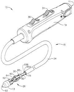
[0011] FIGURE 1 is a perspective view of an anastomotic ring applier
device, shown
with a ring deployment mechanism in an unacluated position.
[0012] FIGURE 2 is a partial perspective view of the distal portion of an
anastomotic
ring applier device holding an anastomotic ring in an unactuated position.
[0013] FIGURE 3 is a partial perspective view of the distal portion of the
device of
FIGURE 2 holding an anastomotic ring in the actuated position.
[0014] FIGURE 4 is a frontal view of an actuated anastomotic ring.
[0015] FIGURE 5 is a perspective view of the device of FIGURE 1, shown with
a
distal portion of the ring deployment mechanism in a partially actuated
position.
[0016] FIGURE 6 is a perspective view of the device of FIGURE 1, shown with
the
distal portion and a proximal portion of the ring deployment mechanism each in
a
partially actuated position.
[0017] FIGURE 7 is a perspective view of the device of FIGURE 1, shown with
the
distal portion and the proximal portion of the ring deployment mechanism each
in a
fully actuated position.
- 3 -
CA 02552933 2006-07-21
[0018] FIGURE 8 is an exploded view of a ring deployment mechanism and a
visualization system of the device of FIGURE 1.
[0019] FIGURE 9 is an exploded view of an actuation mechanism of the device
of
FIGURE 1.
[0020] FIGURE 10 is a partial cross-sectional view of the device of FIGURE
1,
shown with the ring deployment mechanism in an unactuated position.
[0021] FIGURE 11 is a partial cross-sectional view of the device of FIGURE
1, taken
along Plane 11 of FIGURE 10, shown with the ring deployment mechanism in an
unactuated position.
[0022] FIGURE 12 is a partial cross-sectional view of the device of FIGURE
1,
shown with a distal portion of the ring deployment mechanism in a partially
actuated
position.
[0023] FIGURE 13 is a partial cross-sectional view of the device of FIGURE
1,
shown with the distal portion and a proximal portion of the ring deployment
mechanism each in a partially actuated position.
[0024] FIGURE 14 is a partial cross-sectional view of the device of FIGURE
1,
shown inserted through an anastomotic opening, with the distal portion and the
proximal portion of the ring deployment mechanism each in a fully actuated
position.
[0025] FIGURE 15 is a cross-sectional view taken at Plane 15 of the device
of
FIGURE 10.
[0026] FIGURE 16 is a cross-sectional view taken at Plane 16 of the device
of
FIGURE 10.
[0027] FIGURE 17 is a cross-sectional view taken at Plane 17 of the device
of
FIGURE 10.
DETAILED DESCRIPTION OF EMBODIMENTS OF THE INVENTION
[0028] Turning to the Drawings, wherein like numerals denote like
components
throughout the several views, FIG. 1 depicts an applier 10 that is operable to
deploy
and actuate an anastomotic ring device 14 (not pictured in FIG. 1) from a
generally
- 4 -
CA 02552933 2006-07-21
cylindrical shape to one having properties of a hollow rivet, or ring, capable
of
forming an anastomotic attachment at an anastomosis target site, such as in a
bariatric
gastric bypass of a morbidly obese patient. FIG. 2 depicts another applier 12.
It will
be appreciated that appliers 10, 12 may be used in a variety of ways,
including but not
limited to laparoscopically or endoscopically. Applier 12 is shown in FIG. 2
with an
anastomotic ring 14 on a deployment mechanism 16. In FIG. 2, anastomotic ring
14
is shown in the compressed, cylindrically-shaped position. In FIG. 3,
deployment
mechanism 16 of applier 12 has moved anastomotic ring 14 to the actuated,
hollow
rivet-shaped position. FIG. 4 is a close-up view of anastomotic ring 14 in the
actuated
position. Anastomotic ring 14 may comprise a shape memory effect (SME)
material,
such as nitinol by way of example only, that further assists in actuation to
an engaging
hollow rivet shape. Other suitable anastomotic ring 14 materials will be
apparent to
those of ordinary skill in the art. An exemplary anastomotic ring 14 is
described in
detail in U.S. Patent Application Publ. No. US 2003/0032967 to Park et al.
[0029] It will be appreciated that the terms "proximal" and "distal" are
used herein
with reference to a clinician gripping a handle of applier 10. It will be
further
appreciated that for convenience and clarity, spatial terms such as "right",
"left",
"vertical" and "horizontal" are used herein with respect to the drawings.
However,
surgical instruments are used in many orientations and positions, and these
terms are
not intended to be limiting and absolute. In addition, aspects of the
invention have
application to surgical procedures performed endoscopically and
laparoscopically, as
well as an open procedure or other procedures. Use herein of one of these or
similar
terms should not be construed to limit the present invention for use in only
one
category of surgical procedure.
[0030] Referring now to FIGS. 1 and 5-15, applier 10 of the present example
has a
shaft 15 comprising a tubular sheath 24. A handle 19 is positioned at the
proximal
end of shaft 15, while a ring deployment mechanism 26 is positioned at the
distal end
of shaft 15. A tip 13 is positioned at the distal end of ring deployment
mechanism 26.
Applier 10 further comprises an imaging element 11. Imaging element 11 is
coupled
with a camera 90 having a lens 92. Camera 90 and lens 92 are positioned in tip
13.
Camera 90 may be a CCD camera, a CMOS camera, or any other imaging device.
Imaging element 11, camera 90, and lens 92 are configured to provide
visualization
- 5 -
CA 02552933 2006-07-21
through tip. Any suitable device, examples of which will be apparent to those
of
ordinary skill in the art, may be coupled with the proximal end of imaging
element 11
for viewing images communicated through imaging element 11. Other suitable
configurations for permitting imaging element 11 to capture a view will be
apparent
to those of ordinary skill in the art. In one embodiment, imaging element 11
comprises one or more imaging fibers. In one embodiment, illumination is
provided
at the distal end of imaging element 11 by illumination fibers (not pictured)
that run
adjacent imaging element 11. It will be appreciated that such illumination may
aid in
the capture of images by imaging element 11 during use of applier 10. Suitable
configurations of illumination fibers will be apparent to those of ordinary
skill in the
art. Of course, illumination may be provided by a variety of alternative
means,
devices, methods, and/or configurations, or may be eliminated.
100311 In the present example, ring deployment mechanism 26 comprises a
plurality
of proximal fingers 60 connected to a proximal ring 30; and a plurality of
distal
fingers 62 connected to a distal ring 32. A stationary mid-ring 64 is
longitudinally
positioned between proximal ring 30 and distal ring 32. Both proximal fingers
60 and
distal fingers 62 are in a double-hinged relationship with stationary mid-ring
64 of
ring deployment mechanism 26. Proximal ring 30 is configured to slide distally
toward mid-ring 64, causing proximal fingers 60 to actuate outwardly relative
to shaft
15. Mid-ring 64 is held stationary by a stationary distal ground tube portion
65B, as
will be described below. Likewise, distal ring 32 is configured to slide
proximally
toward mid-ring 64, causing distal fingers 62 to actuate outwardly relative to
shaft 15.
Fingers 60, 62 are configured to hold an anastomotic ring 14 by engaging
petals 52
prior to and during deployment of the anastomotic ring 14, and release petals
52 upon
deployment of the anastomotic ring 14.
[0032] Applier 10 further comprises a pair of deployment actuators 34, 36.
As
described in more detail below, first deployment actuator 34 is operable to
actuate
proximal fingers 60 of ring deployment mechanism 26 by advancing proximal ring
30
distally; and second deployment actuator 36 is operable to actuate distal
fingers 62 by
pulling distal ring 32 proximally. In FIGS. 5 and 12, distal fingers 62 are
shown in a
partially actuated position for partially deploying a distal portion of an
anastomotic
ring 14. Arrow 42 depicts actuating motion of second actuator 36. In FIGS. 6
and 13,
- 6 -
CA 02552933 2006-07-21
proximal fingers 60 are shown in a partially actuated position for partially
deploying a
proximal portion of anastomotic ring 14 to partially complete an anastomotic
attachment between proximate tissue walls 46, 48. Arrow 50 depicts the
actuating
motion of first actuator 34. FIGS. 7 and 14 show fingers 60, 62 in a fully
actuated
position, effecting deployment of anastomotic ring 14. It will be appreciated
that any
suitable alternative(s) to ring deployment mechanism 26 and/or deployment
actuators
34, 36 may be used.
[00331 As stated above, first deployment actuator 34 of the present example
is
operable to control proximal fingers 60; and second deployment actuator 36 is
operable to control distal fingers 62. Referring to FIGS. 9 and 16-17, first
and second
ring deployment actuators 34, 36 each have a pair of grooves 67 that are
configured to
slide on a track 68 of handle 19. The range of first actuator 34 is limited by
the width
of a slot 70, while the range of second actuator 36 is limited by the width of
a slot 72.
In the present example, first actuator 34 is fixedly attached to a proximal
portion 74 of
track 68. Track 68 is slideable within handle 19. A distal portion 76 of track
68 is
fixedly attached to a slider 78. Slider 78 is fixedly connected to a pair of
push cables
80. Longitudinal motion of first actuator 34 is thereby operable to cause
corresponding longitudinal motion of track 68, slider 78, and push cables 80.
Other
suitable relationships between these components, as well as alternative
components
and configurations, will be apparent to those of ordinary skill in the art.
[0034] Referring to FIG. 15, push cables 80 are each positioned within a
respective
cable sheath 79. Each cable sheath 79 extends longitudinally through a
respective
cable conduit 27 in shaft 15. In the present example, cable conduits 27 are
formed in
sheath 24.
[0035] Referring to FIGS. 8 and 10-15, the distal end of each push cable 80
is fixedly
secured to the proximal end of a push tube 85. The distal end of push tube 85
has a
pair of flanges 81, which are configured to engage with proximal ring 30 of
ring
deployment mechanism 26. Accordingly, push tube 85 is operable to communicate
longitudinal motion to proximal ring 30, thereby actuating or deactuating
proximal
fingers 60. Because of engagement between push cables 80 and push tube 85,
such
- 7 -
CA 02552933 2006-07-21
longitudinal motion may be provided by actuation of first actuator 34. Of
course, any
other suitable components or configurations may be used.
100361 Shaft 15 further comprises a proximal ground tube portion 65A
extending
longitudinally therethrough. The proximal end of proximal ground tube portion
65A
is fixedly attached to anchor member 84. Anchor member 84 is configured to
engage
with bosses 86, which are integral with handle 19. Accordingly, in the present
example, anchor member 84 and bosses 86 are configured to prevent relative
movement between proximal ground tube portion 65A and handle 19. Proximal
ground tube portion 65A extends longitudinally through ground tube conduit 25,
which is formed in sheath 24 adjacent to and between cable conduits 27. A
distal
ground tube portion 65B is fixedly secured to proximal ground tube portion
65A. The
distal end of distal ground tube portion 65B has a flange 66, which is
configured to
engage mid-ring 64 of ring deployment mechanism 26. Ground tube portions 65A,
65B thus prevent longitudinal movement of mid-ring 64 relative to handle 19.
It will
be appreciated that any other suitable components or configurations may be
used.
[0037] Second actuator 36 is fixedly secured to a proximal inner tube
portion 82A,
which extends longitudinally through proximal ground tube portion 65A. A
distal
inner tube portion 82B is fixedly secured to proximal inner tube portion 82A.
Distal
inner tube portion 82B extends longitudinally through distal ground tube
portion 65B.
The distal end of distal inner tube portion 82B has a pair of flanges 83,
which are
configured to engage with distal ring 32 of ring deployment mechanism.
Accordingly, distal inner tube portion 82B is operable to communicate
longitudinal
motion to distal ring 32, thereby actuating or deactuating distal fingers 62.
Because of
engagement between distal inner tube portion 82B and proximal inner tube
portion
82A, such longitudinal motion may be provided by actuation of second actuator
36.
Of course, any other suitable components or configurations may be used.
[0038] It should be noted that although second actuator 36 is configured to
slide on
track 68 in the present example, second actuator 36 is not statically attached
to track
68. Therefore, longitudinal movement of track 68 caused by motion of first
actuator
34 does not cause longitudinal movement of second actuator 36. Of course,
handle 19
and components thereof may be configured in any other suitable way. By way of
- 8 -
CA 02552933 2006-07-21
example only, first actuator 34 may be configured to control actuation of
distal fingers
62, and second actuator 36 may be configured to control actuation of proximal
fingers
60. Still other suitable alternative configurations will be apparent to those
of ordinary
skill in the art.
[0039] It will be appreciated that applier 10 of the present example may be
used to
deploy an anastomotic ring 14 without the involvement of a nonfunctional
enterotomy. For instance, applier 10 may be configured such that tip 13, ring
deployment mechanism 26, and shaft 15 may be inserted down the esophagus of a
patient. Accordingly, shaft 15 may be sized (e.g., as to diameter and length)
to reach
an anastomosis site transorally, via the esophagus. Particularly when imaging
element 11, camera 90, and lens 92 are included in applier 10, such use may
eliminate
the need for at least one trocar port in the abdomen or elsewhere in the
patient. Of
course, applier 10 may be used in any other suitable way, including but not
limited to
use through a nonfunctional enterotomy or use in an open procedure.
[0040] In the present example, shaft 15 is flexible. However, it will be
appreciated
that shaft 15, including components thereof, may have any other properties,
including
but not limited to malleability, rigidity, resilience, other properties, or
combinations
thereof. It will also be appreciated that components of applier 10 may have
any
suitable dimensions. By way of example only, tip 13, ring deployment mechanism
26, and/or shaft may have a maximum outer diameter between approximately 12
and
18 mm. Of course, any other dimensions may be used.
[0041] In another embodiment, one or more tubes 82A, 82B, 65A, 65B, and/or
85 are
eliminated, and cables are substituted therefor. For instance, a pull cable
may be
substituted for proximal inner tube portion 82A. Cables may be individually
sheathed
and/or bundled together, or have any other components or configurations. It
will be
appreciated that, by providing sheaths about cables, buckling of the cables
may be
prevented. Of course, sheaths may provide other advantages over sheathless
cables,
or may provide no advantages at all. As with several other components,
sheaths,
including but not limited to cable sheaths 79, are optional. For instance,
cable sheath
conduits 27 may be configured to provide sheathing for push cables 80.
- 9 -
CA 02552933 2006-07-21
[0042] In yet another embodiment, shaft 15 comprises one or more working
channels.
By way of example only, such channels may be used to introduce micro forceps
or
any other device. Where micro forceps are included, the same may be used to
grasp
tissue to be cut or anastomosed. Other variations will be apparent to those of
ordinary
skill in the art.
[0043] In still another embodiment, proximal ground tube portion 65A is
eliminated,
and ground tube conduit 25 provides grounding for mid-ring 64. In one version
of
this embodiment, the proximal end of ground tube conduit 25 extends into
handle 19
further than other portions of sheath 24, and is fixedly secured to anchor
member 84.
In this alternate version, the distal end of ground tube conduit 25 is fixedly
secured to
distal ground tube portion 65B. Any other variation of, substitute for, or
supplement
to ground tube 65A, 65B may be used.
[0044] In use, applier 10 may be inserted adjacent an anastomotic opening
in
proximate tissue walls 46, 48. Imaging element 11, camera 90, and lens 92 may
be
used to capture a view of the anastomosis site, such as to properly position
applier 10.
As shown in FIGS. 5 and 12, second actuator slider 36 may be partially
actuated to
partially actuate distal fingers 62, thereby partially deploying a distal
portion of
anastomotic ring 14. As shown in FIGS. 6 and 13, first actuator slider 34 may
be
partially actuated to partially actuate proximal fingers 60, thereby partially
deploying
a proximal portion of anastomotic ring 14. The surgeon may then confirm proper
positioning of applier 10, such as through tactile feedback or through any
other
technique. As shown in FIGS. 7 and 14, first and second actuator sliders 34,
36 may
be fully actuated to fully actuate ring deployment mechanism 26, thereby
completing
deployment of anastomotic ring 14 to effect an anastomosis. After anastomotic
ring
14 has been deployed, the above steps may be reversed, and applier 10 may be
withdrawn. Other variations of use of applier 10 will be apparent to those of
ordinary
skill in the art.
[00451 While applier 10 has been described as being operable to deploy an
anastomotic ring 14, it will be appreciated that applier 10 may have a variety
of other
uses. By way of example only, where an anastomotic ring 14 has already been
deployed, applier 10 may be used to compress or otherwise modify or manipulate
the
- 10-
CA 02552933 2013-07-02
=
deployed anastomotic ring 14. Still other uses will be apparent to those of
ordinary
skill in the art.
100461 1-laying shown and described various embodiments and concepts of
the
invention, further adaptations of the methods and systems described herein can
be
accomplished by appropriate modifications by one of ordinary skill in the art
without
departing from the scope of the invention. Several of such potential
alternatives,
modifications, and variations have been mentioned, and others will be apparent
to
those skilled in the art in light of the foregoing teachings.
-II -