Language selection

Search

Patent 2553112 Summary

Third-party information liability

Some of the information on this Web page has been provided by external sources. The Government of Canada is not responsible for the accuracy, reliability or currency of the information supplied by external sources. Users wishing to rely upon this information should consult directly with the source of the information. Content provided by external sources is not subject to official languages, privacy and accessibility requirements.

Claims and Abstract availability

Any discrepancies in the text and image of the Claims and Abstract are due to differing posting times. Text of the Claims and Abstract are posted:

  • At the time the application is open to public inspection;
  • At the time of issue of the patent (grant).
(12) Patent Application: (11) CA 2553112
(54) English Title: TOOL VEST
(54) French Title: GILET PORTE-OUTILS
Status: Deemed Abandoned and Beyond the Period of Reinstatement - Pending Response to Notice of Disregarded Communication
Bibliographic Data
(51) International Patent Classification (IPC):
  • A41D 1/04 (2006.01)
  • A41D 27/20 (2006.01)
  • A45F 5/02 (2006.01)
(72) Inventors :
  • ABIFARAJ, HAISSAM (Canada)
(73) Owners :
  • HAISSAM ABIFARAJ
(71) Applicants :
  • HAISSAM ABIFARAJ (Canada)
(74) Agent: DOUGLAS B. THOMPSONTHOMPSON, DOUGLAS B.
(74) Associate agent:
(45) Issued:
(22) Filed Date: 2006-07-18
(41) Open to Public Inspection: 2008-01-18
Availability of licence: N/A
Dedicated to the Public: N/A
(25) Language of filing: English

Patent Cooperation Treaty (PCT): No

(30) Application Priority Data: None

Abstracts

English Abstract


A tool vest includes a vest body adapted to be worn by an individual, with the
vest
body having an external surface with multiple tool receivers. Each tool
receiver has a means
for securing a tool received by the tool receiver. At least one retractable
line is adapted for
connection to a tool to secure the tool when not received by one of the
multiple tool receivers.


Claims

Note: Claims are shown in the official language in which they were submitted.

5
What is Claimed is:
1. A tool vest, comprising:
a vest body adapted to be worn by an individual, the vest body having an
external
surface with multiple tool receivers, each tool receiver having means for
securing a tool
received by the tool receiver;
at least one retractable line adapted for connection to a tool to secure the
tool when
not received by one of the multiple tool receivers.
2. The tool vest of claim 1, wherein tools are provided each of which having a
first portion of
a two part fastener system and a remote end of the retractable line has a
second portion of the
two part fastener system, thereby enabling selected tools to be configured of
the vest body to
suit a particular job.
3. The tool vest of claim 1, wherein apertures are provided in the vest body
for accessing a
safety harness worn by the individual.
4. The tool vest of claim 1, wherein the tool receivers comprise tool-
receiving pockets, the
means for securing the tool comprising securable flaps for securing the tools
in the pockets.
5. The tool vest of claim 1, wherein the vest body has tightening straps to
tighten the vest
body to the individual.
6. The tool vest of claim 1, comprising two retractable lines.

Description

Note: Descriptions are shown in the official language in which they were submitted.


CA 02553112 2006-07-18
1
TITLE
Tool vest
FIELD
The present application relates to a tool vest for use by workers using tools
at heights,
specifically with a safety restraint.
BACKGROUND
If a worker drops a tool when working at an elevated position, the falling
tool presents
a hazard to workers on the ground below. United States Patent 4,177,877
(Gallinati) is an
example of a tool vest developed for use by workers working on scaffolding. A
lanyard is
provided for securing to a power tool, such as a drill. Pockets are provided
to accommodate
various hands tools, such as screw drivers and wrenches, that the worker may
require.
SUMMARY
There is provided a tool vest includes a vest body adapted to be worn by an
individual, with the vest body having an external surface with multiple tool
receivers. Each
tool receiver has a means for securing a tool received by the tool receiver.
At least one
retractable line is adapted for connection to a tool to secure the tool when
not received by one
of the multiple tool receivers.
The tool vest illustrated in United States Patent 4,177,877 was not effective
in
addressing the underlying safety issues. Tools had to be removed from the
pockets of the tool
vest in order to be used. During use, incidents still occurred with tools
being dropped onto
workers below. Furthermore, the use of a lanyard created a new safety hazard,
as the power
tool dangling at the end of the lanyard swung or caught on objects as the
worker ascended or
descended the scaffolding. The tool vest described above addresses the problem
by ensuring
that every tool accommodated by the tool vest is secured against being
dropped.
BRIEF DESCRIPTION OF THE DRAWINGS
These and other features will become more apparent from the following
description in
which reference is made to the appended drawings, the drawings are for the
purpose of

CA 02553112 2006-07-18
2
illustration only and are not intended to be in any way limiting, wherein:
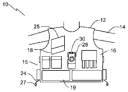
FIG. 1 is a front elevation view of the too] vest being worn by an individual.
FIG. 2 is a rear elevation view of the tool vest being worn by an individual.
FIG. 3 is a side plan view of the tool vest being worn by a person with a
safety line
attached to the safety harness.
FIG. 4 is a detailed front elevation view of tools positioned within a tool
receiver.
FIG. 5 is a front elevation view of a person wearing a safety harness.
FIG. 6 is a perspective view of various tools to be used with the tool vest.
DETAILED DESCRIPTION
A tool vest generally identified by reference numeral 10, will now be
described with
reference to FIG. 1 through 6.
Structure and Relationship of Parts:
Referring to FIG. 1, tool vest 10 includes a vest body 12 adapted to be worn
by an
individual 14, with tightening straps 15 to tighten vest body 12 to individual
14. It is preferred
that tightening straps 15 be designed such that they do not hang loose at the
sides of the user,
which could be a hazard. Vest body 12 has an external surface 16 with multiple
tool
receiving pockets 18 and pouches 19. It is preferred that vest body 12,
pockets 18 and
pouches 19 be made from oil resistant and tear resistant material to prolong
life and make it
easier to clean. Referring to FIG. 4, tools 20 are positioned within tool
receiving pockets 18,
and secured by securing flaps 25. It is preferred that each pocket 18 or pouch
19 be tool
specific, and that tools 20 are held by securing flaps 25 individually. In
this manner, if
individual 14 slips and turns upside down while a pouch or pocket is still
open, for example
while securing a tool 20, other tools 20 will still remain secured. Each tool
20 has the first
portion 22 of a two part fastener system. Referring to FIG. 1, retractable
lines 24 have the
second portion 27 of the two part fastener system, thereby enabling selected
tools to be
configured of the vest body to suit a particularjob. Retractable lines 24 act
to arrest the fall of
tools 20 if accidentally dropped when being used, and retract when not in use
to prevent
becoming a hazard, such as by snagging on equipment, or being caught in moving
parts such
as drive shafts or pulleys. The two part fastener system may be, for example,
a loop that is
connected by a double latching carabiner. As tools 22 are secured within
pocket 18 by

CA 02553112 2006-07-18
3
securable flap 25, tools 20 are secured at all times to vest body 12 either
within pockets 18 by
flaps 25, or by being attached to retractable lines 24 when in use. Referring
to FIG. 2, vest
body 12 may also have rigid loops 26 for carrying tools such as hammers. Rigid
loops 26
may not be included if it is felt that they may be used improperly, such as
for fall restraint. In
this case, they may be replaced with a more suitable tool holder. Referring to
FIG. 1 and 2,
as tool vest 10 is intended to be worn over personal protective clothing as
well as a safety
harness 28 worn by individual 14, apertures 30 are provided in vest body 12 in
both front and
back for accessing safety harness 28. FIG. 3 shows safety harness 28 attached
to a tether
strap 32. An example of a safety harness 28 is shown in FIG. 5, although other
types of
harnesses 28 can also be accommodated by vest body 12. As such, tool vest 10
is designed
such that it does not interfere with fall restraint systems. Tools 20 are
therefore restrained by
tool vest 10, while harness 28 provides individual protection, keeping the
roles of each
separate.
Referring to FIG. 6, various types of tools 20 may used, each having a first
portion 22
of a two part fastener system, and may be modified from existing tools. Some
tools come
with hole, and these may be modified by inserting cable 48 and making a loop.
Others, for
example, a screwdriver 34 may be modified by drilling a hole and inserting an
eye ring 36.
Other tools, such as pliers 38, may be modified by welding eye ring 36
directly onto the
handle 42. In some circumstances, it may be more practical to drill a hole 44
such as through
the flat handle 42 of wire strippers 46 and inserting cable 48 to make a loop.
Finally, other
tools such as wrenches 50 may be modified by simply tightening cable 48 about
it such that it
will not be able to slide off.
2 5 Operation:
Referring to FIG. 1 through 6, the use and operation of tool vest 10 as
described
above will now be given. Referring to FIG. 5, the individual 14 attaches any
special clothing
(e.g. for cold weather, etc., not shown) and safety harness 28. Referring to
FIG. 3, vest body
12 is then worn over top of safety harness 28, and attached to tether strap
32. Tightening
straps 15 are used to adjust the size of vest body 12 to suit individual 14
and any extra
clothing. Referring to FIG. 4, tools 20 are placed in pockets 18 and secured
by flaps 25.
Referring to FIG. 1 and 2, tools 20 may also be secured in pouches 19 or rigid
loops 26. As

CA 02553112 2006-07-18
4
each tool 20 is needed, first portion 22 of the two part fastener system (seen
in FIG. 6) is
attached to second portion 27, such that tool 20 is secured against being
accidentally dropped.
In this patent document, the word "comprising" is used in its non-limiting
sense to
mean that items following the word are included, but items not specifically
mentioned are not
excluded. A reference to an element by the indefinite article "a" does not
exclude the
possibility that more than one of the element is present, unless the context
clearly requires that
there be one and only one of the elements.
It will be apparent to one skilled in the art that modifications may be made
to the
illustrated embodiment without departing from the spirit and scope defined in
the Claims.

Representative Drawing
A single figure which represents the drawing illustrating the invention.
Administrative Status

2024-08-01:As part of the Next Generation Patents (NGP) transition, the Canadian Patents Database (CPD) now contains a more detailed Event History, which replicates the Event Log of our new back-office solution.

Please note that "Inactive:" events refers to events no longer in use in our new back-office solution.

For a clearer understanding of the status of the application/patent presented on this page, the site Disclaimer , as well as the definitions for Patent , Event History , Maintenance Fee  and Payment History  should be consulted.

Event History

Description Date
Application Not Reinstated by Deadline 2010-07-19
Time Limit for Reversal Expired 2010-07-19
Deemed Abandoned - Failure to Respond to Maintenance Fee Notice 2009-07-20
Small Entity Declaration Determined Compliant 2008-07-18
Small Entity Declaration Request Received 2008-07-18
Application Published (Open to Public Inspection) 2008-01-18
Inactive: Cover page published 2008-01-17
Inactive: Adhoc Request Documented 2008-01-02
Revocation of Agent Request 2007-11-16
Appointment of Agent Request 2007-11-16
Inactive: IPC assigned 2006-10-23
Inactive: First IPC assigned 2006-10-23
Inactive: IPC assigned 2006-10-23
Inactive: Filing certificate - No RFE (English) 2006-08-21
Filing Requirements Determined Compliant 2006-08-21
Application Received - Regular National 2006-08-21

Abandonment History

Abandonment Date Reason Reinstatement Date
2009-07-20

Maintenance Fee

The last payment was received on 2008-07-18

Note : If the full payment has not been received on or before the date indicated, a further fee may be required which may be one of the following

  • the reinstatement fee;
  • the late payment fee; or
  • additional fee to reverse deemed expiry.

Please refer to the CIPO Patent Fees web page to see all current fee amounts.

Fee History

Fee Type Anniversary Year Due Date Paid Date
Application fee - small 2006-07-18
MF (application, 2nd anniv.) - small 02 2008-07-18 2008-07-18
Owners on Record

Note: Records showing the ownership history in alphabetical order.

Current Owners on Record
HAISSAM ABIFARAJ
Past Owners on Record
None
Past Owners that do not appear in the "Owners on Record" listing will appear in other documentation within the application.
Documents

To view selected files, please enter reCAPTCHA code :


To view images, click a link in the Document Description column. To download the documents, select one or more checkboxes in the first column and then click the "Download Selected in PDF format (Zip Archive)" or the "Download Selected as Single PDF" button.

List of published and non-published patent-specific documents on the CPD .

If you have any difficulty accessing content, you can call the Client Service Centre at 1-866-997-1936 or send them an e-mail at CIPO Client Service Centre.


Document
Description 
Date
(yyyy-mm-dd) 
Number of pages   Size of Image (KB) 
Abstract 2006-07-18 1 8
Drawings 2006-07-18 3 34
Description 2006-07-18 4 156
Claims 2006-07-18 1 25
Representative drawing 2007-12-21 1 7
Cover Page 2008-01-07 1 29
Filing Certificate (English) 2006-08-21 1 158
Reminder of maintenance fee due 2008-03-19 1 113
Courtesy - Abandonment Letter (Maintenance Fee) 2009-09-14 1 172
Correspondence 2006-08-21 1 48
Correspondence 2007-11-16 5 123
Correspondence 2008-03-19 1 37
Correspondence 2008-07-18 2 66
Fees 2008-07-18 2 66
Correspondence 2009-09-14 1 52